patent · US5128115
Manufacture of silicon carbide using solar energy
7 July 1992
Page 1 — bibliographic record
United States Patent (19) 11) Patent Number: 5,128,115 Glatzmaier (45) Date of Patent: Jul. 7, 1992 (54) MANUFACTURE OF SILICON CARBIDE 4.534,948 8/1985 Baney .................................. 423/345 USING SOLAR ENERGY 4.702.900 10/987 Kurachi et al. ... 423/345 4,789,536 12/1988 Schramm et al. . ... 423/345 75) inventor: Gregory C. Glatzmaier, Boulder, 4,904,622 2/1990 Dubots et al. .... ... 50/88 Colo. 4,915,924 4/1990 Nadkarni et al. . ... 423/345 5,021,230 6/1991 Krstic .................................. 423/345 (73) Assignee: The United States of America as represented by the United States Primary Examiner-Robert Kunemund
Department of Energy, Washington, Assistant Examiner-Ken Horton
D.C. Attorney, Agent, or Firm-Kenneth Richardson; James
W. Weinberger; William R. Moser (21) Appl. No.: 681,296 (57) ABSTRACT 22) Filed: Apr. 8, 1991 A method is described for producing silicon carbide 51) Int. Cl. .............................................. CO1B 31/36 particles using solar energy. The method is efficient and 52 U.S. Cl. .................................... 423/345; 423/344: avoids the need for use of electrical energy to heat the 23/295 S reactants. Finely divided silica and carbon are admixed 58) Field of Search ....................... 423/344, 345, 346; and placed in a solar-heated reaction chamber for a time 23/295 S; 501/88 sufficient to cause a reaction between the ingredients to (56) References Cited form silicon carbide of very small particle size. No grinding of silicon carbide is required to obtain small
2.987.96 6/961 Cotton et al. ....................... 359/853 process or as a continuous process.
4,419,336 l2/1983 Kuriskose ........................... 423/345 14 Claims, 2 Drawing Sheets
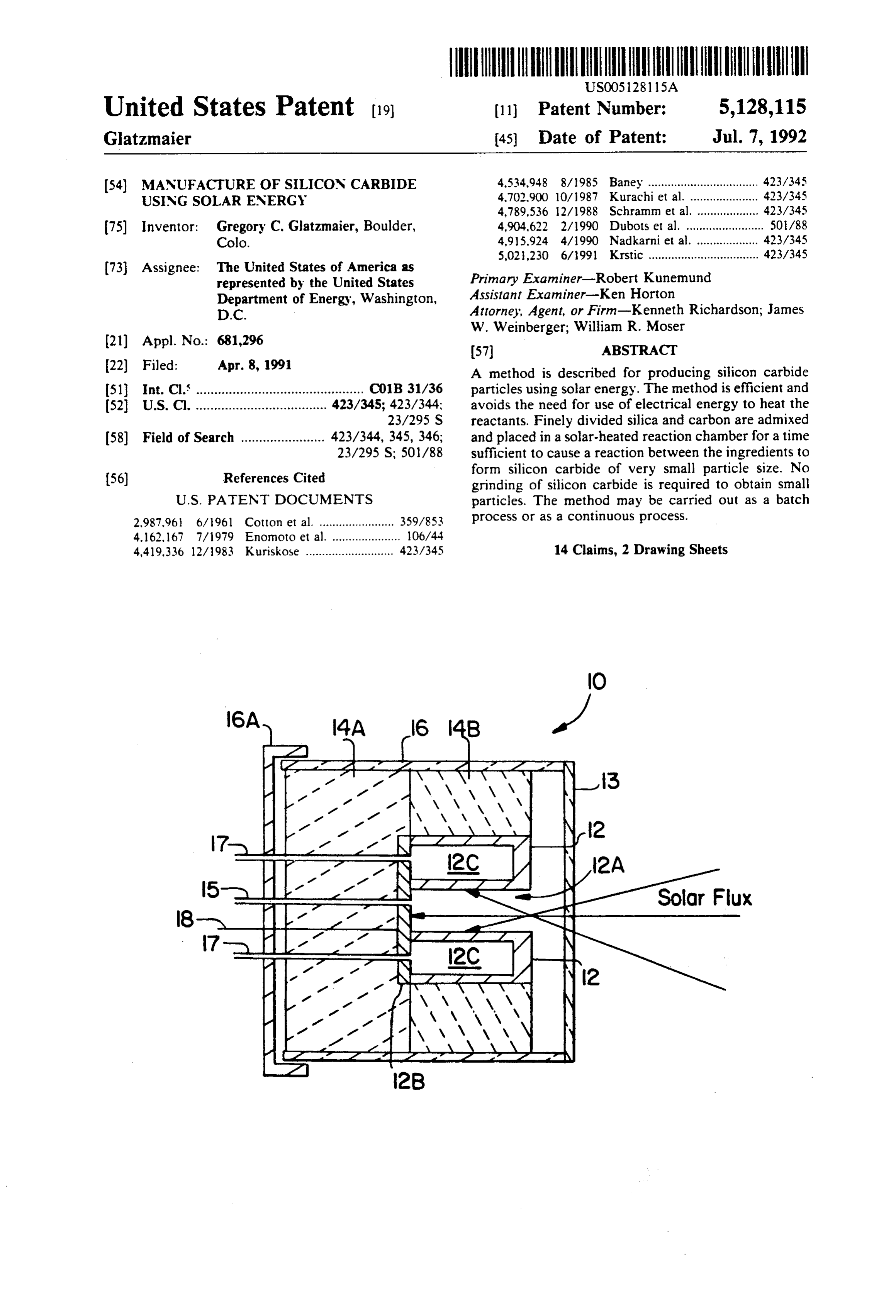
5 N Solor Flux 8 1. 1. -N 5
Page 2
Drawing sheet — no readable text.
Page 3
Drawing sheet — no readable text.
Page 4
1800° C. The heating period is followed by a cooling
MANUFACTURE OF SILICON CARBIDE USING period of 20 hours. The bed produces silicon carbide SOLAR ENERGY ingots that range in size from 1 foot in diameter down to diameters of approximately 100 microns. The reacted
CONTRACTUAL ORIGIN OF THE INVENTION 5 material is manually fed to a crusher to reduce the size The United States Government has rights in this of the ingots to small particles. The particles are then invention under Contract No. DE-AC02-83CH 10093 chemically treated with acid to remove unreacted silica between the United States Department of Energy and along with contaminants from the crushing process. the Solar Energy Research Institute, a Division of the O Excess carbon is removed by oxidation at temperatures Midwest Research Institute. less than 500 C. The particles are then screened and
BACKGROUND OF THE INVENTON
classified according to particle size and shape.
The costs associated with handling large quantities of 1. Field of the Invention electricity, and the costs associated with crushing the The present invention relates, generally, to methods 15 silicon carbide to smaller particles, account for the for producing silicon carbide and, more particularly to major costs in producing the material using conven methods for producing silicon carbide particles using tional techniques.
solar thermal energy:Specifically, the present invention U.S. Pat. No. 4,419,336 (Kuriakose) describes an in relates to improved methods which are more efficient proved electric resistance furnace for producing silicon than previously available for producing silicon carbide 20 carbide. U.S. Pat. No. 4,534,948 (Baney) describes a particles. process for producing silicon carbide using specific 2. Description of the Prior Art polysilane polymers as starting materials. The polymer Silicon carbide is an abrasive material which is is heated to 1600 C. in an inert atmosphere to form widely used in a variety of grinding and polishing appli silicon carbide. The main advantage of this approach is cations. Its hardness is 9.5 on the Mohs scale and there fore is only slightly less than the hardness of diamond that25 the polymer can be pre-formed into fibers or other shapes which the silicon carbide assumes when it forms.
(which is 10 on the same scale).
Silicon carbide is made by reacting silica with carbon silicon carbide do
These patents not describe a process for forming using a solar furnace.
at 1800-1900 C. The chemical reaction for the process U.S. Pat. No. 2,987,961 (Cotton et al.) describes a
30 solar furnace and improved concentrator for focusing
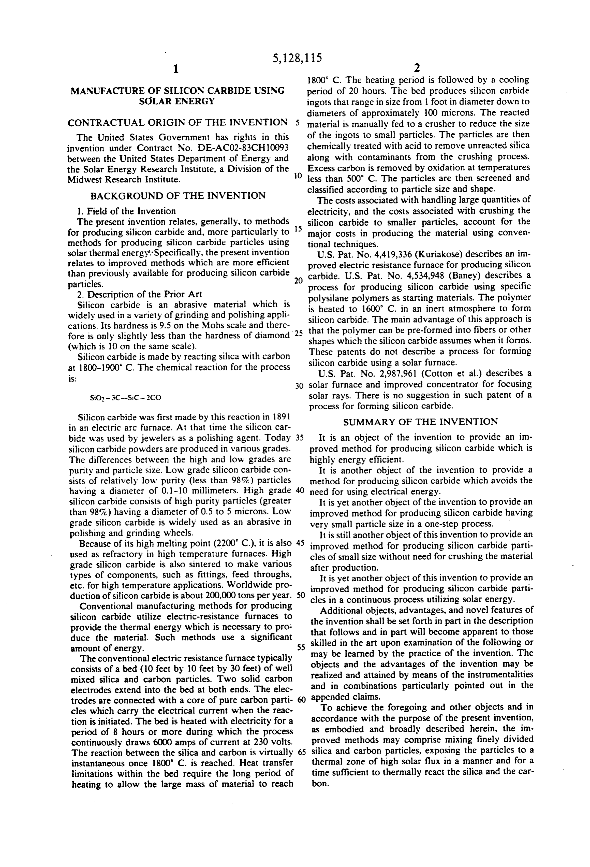
SiO-3C-SiC + 2CO solar rays. There is no suggestion in such patent of a process for forming silicon carbide.
Silicon carbide was first made by this reaction in 1891 SUMMARY OF THE INVENTION in an electric arc furnace. At that time the silicon car bide was used by jewelers as a polishing agent. Today 35 It is an object of the invention to provide an im silicon carbide powders are produced in various grades. proved method for producing silicon carbide which is The differences between the high and low grades are highly energy efficient.
purity and particle size. Low grade silicon carbide con It is another object of the invention to provide a sists of relatively low purity (less than 98%) particles method for producing silicon carbide which avoids the having a diameter of 0.1-10 millimeters. High grade need for using electrical energy.
silicon carbide consists of high purity particles (greater It is yet another object of the invention to provide an than 98%) having a diameter of 0.5 to 5 microns. Low improved method for producing silicon carbide having grade silicon carbide is widely used as an abrasive in very small particle size in a one-step process. polishing and grinding wheels. It is still another object of this invention to provide an Because of its high melting point (2200 C.), it is also 45 improved method for producing silicon carbide parti used as refractory in high temperature furnaces. High cles of small size without need for crushing the material grade silicon carbide is also sintered to make various after production.
types of components, such as fittings, feed throughs, It is yet another object of this invention to provide an etc. for high temperature applications. Worldwide pro improved method for producing silicon carbide parti duction of silicon carbide is about 200,000 tons per year. SO cles in a continuous process utilizing solar energy. Conventional manufacturing methods for producing Additional objects, advantages, and novel features of silicon carbide utilize electric-resistance furnaces to provide the thermal energy which is necessary to pro the that invention shall be set forth in part in the description follows and in part will become apparent to those duce the material. Such methods use a significant skilled in the art upon examination of the following or amount of energy. 55 may be learned by the practice of the invention. The
The conventional electric resistance furnace typically consists of a bed (10 feet by 10 feet by 30 feet) of well objects and the advantages of the invention may be realized and attained by means of the instrumentalities mixed silica and carbon particles. Two solid carbon and in combinations particularly pointed out in the electrodes extend into the bed at both ends. The elec trodes are connected with a core of pure carbon parti appended claims.
cles, which carry the electrical current when the reac To achieve the foregoing and other objects and in tion is initiated. The bed is heated with electricity for a accordance with the purpose of the present invention, period of 8 hours or more during which the process as embodied and broadly described herein, the in continuously draws 6000 amps of current at 230 volts. proved methods may comprise mixing finely divided The reaction between the silica and carbon is virtually 65 silica and carbon particles, exposing the particles to a instantaneous once 1800' C. is reached. Heat transfer thermal zone of high solar flux in a manner and for a limitations within the bed require the long period of time sufficient to thermally react the silica and the car heating to allow the large mass of material to reach bon.
Page 5
The process of the invention can be carried out in a The carbon particles preferably have a particle size batch manner or in a continuous manner. The particles less than about 10 microns. Even more preferably the of silicon carbide produced in accordance with this size is about 1 micron.
invention have small particle size and are therefore very The silica and carbon particles are admixed and then desirable commercially. The particles may range in size placed in the compartment 12C of the solar-heated from about 0.5 to 70 microns (preferably 0.5 to 15 mi reaction chamber. Preferably the silica is about 60% by crons, and more preferably 0.5 to 1 micron). weight of the admixture and the carbon is about 40% by Because the process of this invention utilizes solar weight. This ratio of silica to carbon is preferred be energy to heat the reactants, the process avoids the need cause it represents an excess of about 10%-15% carbon. for use of a conventional electrical resistance furnace. 10 The residence time of the admixture in the reaction The desired particle composition and size are formed at compartment is less than about 10 minutes. high temperature in a one-step process. Therefore, the The silicon carbide particles produced in the method crushing step is eliminated. Accordingly, the process of of this invention have very small particle size. Prefera this invention is very efficient. bly they have a size less than about 15 microns. Even 15 more preferably they have a size less than about 1 mi
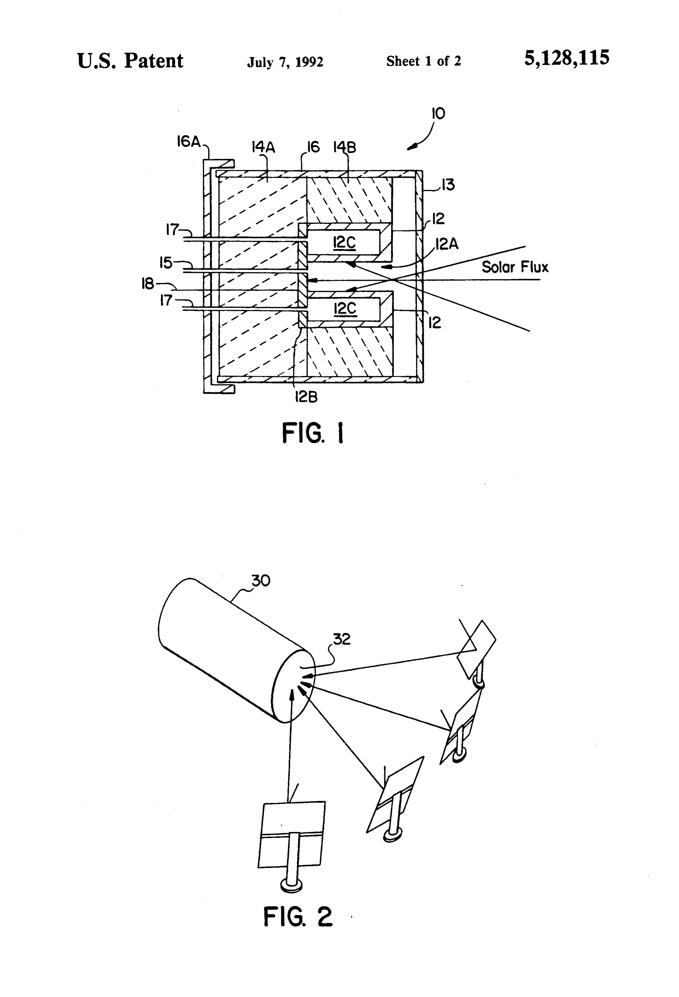
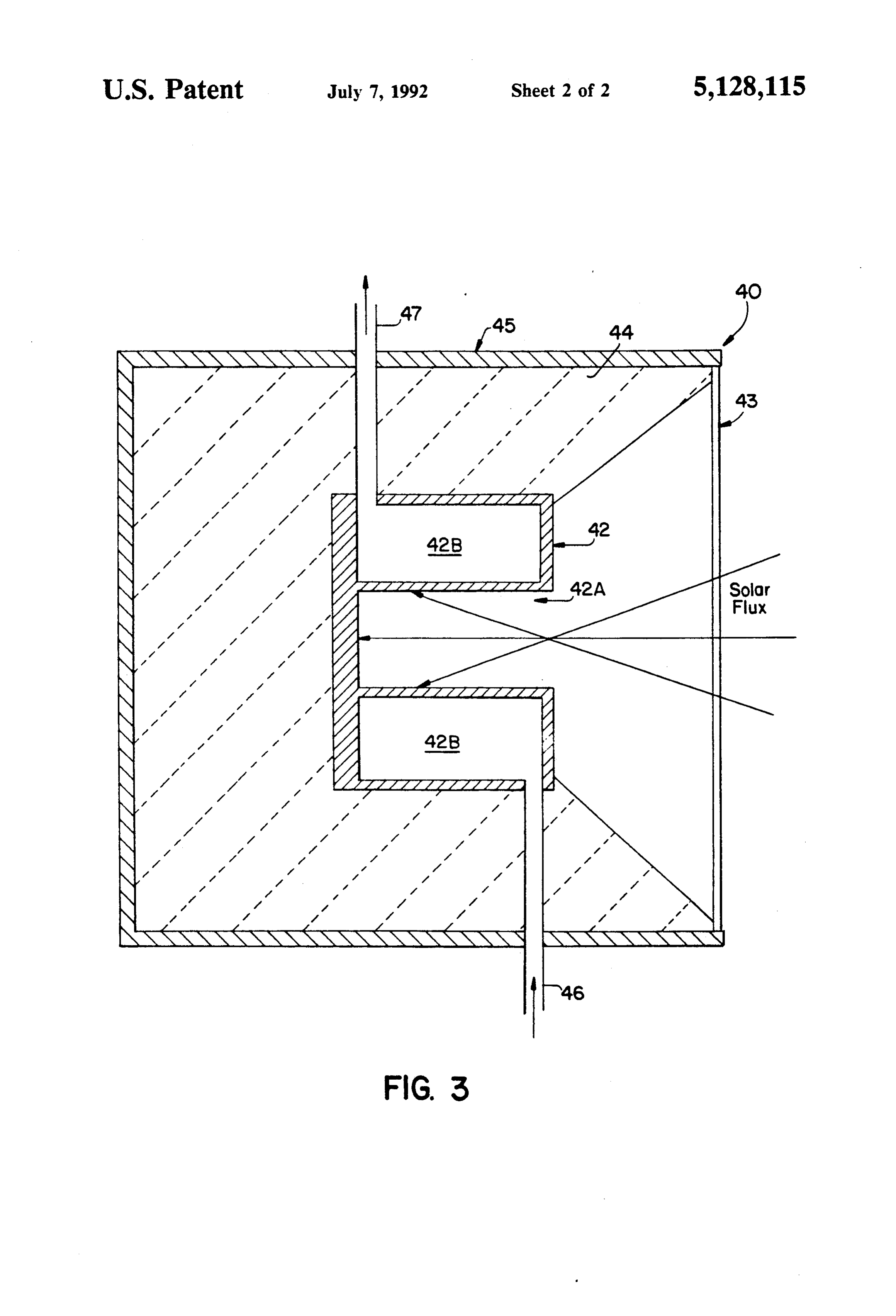
BRIEF DESCRIPTION OF THE DRAWINGS cron. No grinding is required. The accompanying drawings, which are incorpo FIG. 2 illustrates on manner in which sunlight may be rated in and form a part of the specification, illustrate reflected and focused on the end of a cavity in a solar the preferred embodiments of the present invention and, heated reaction chamber. Thus, there are shown a plu with the description, explain the principles of the inven 20 rality of reflectors 20 which are positioned such that tion. they each reflect solar rays into a cavity in a graphite F.G. 1 is a cross-sectional view illustrating one em core (of the type shown in FIG. 1, for example) behind bodiment of reactor assembly which is useful in this window 32 in solar heated reaction chamber 30. The invention. number and size of such reflectors and the size of the FIG. 2 is a perspective view illustrating another em 25 reaction chamber may vary, as desired. Reflectors of bodiment of apparatus which is useful in this invention. this type are well known in the art. FIG. 3 is a cross-sectional view of a reactor assembly FIG. 3 illustrates another type of solar-heated reac useful in a continuous process in accordance with this tion chamber 40 which is useful in the practice of this invention. invention. This apparatus is useful in a continuous pro 30 cess for the production of silicon carbide using the tech
DETALED DESCRIPTION OF THE niques of this invention. The apparatus includes a PREFERRED EMBODIMENTS graphite core 42 including a cavity 42A therein. The FIG. 1 illustrates a preferred reactor assembly 10 core 42 includes a hollow annulus or reaction compart which is useful in a batch process for producing silicon ment 42B.
carbide particles in accordance with this invention. This 35 Surrounding the graphite core is high temperature solar-heated reaction chamber comprises an annular ceramic insulation 44. A stainless steel shell 45 sur graphite core 12 having a central cavity 12A therein. rounds the insulation, and a quartz window 43 is posi The open end of the cavity is covered with a quartz tioned at one end of the chamber, as illustrated, so that window 13. The graphite core is surrounded by high solar energy can pass through it and into cavity 42A. temperature ceramic insulation sections 14 and 14B Preferably the solar rays are focused at the open end of which are in turn enclosed in a quartz shell 16. the cavity. The rays diverge as they enter into the cav The graphite core 12 includes a hollow annulus or ity where they are then absorbed by the walls of the ring-shaped compartment 12C where the reactants are graphite core.
placed in order to be heated to the desired reaction The silica and carbon particles to be reacted are temperature. Access to compartment 12C is obtained by 45 mixed and entrained in an inert gas (nitrogen or helium) removing cover 16A, tubes 15 and 17, and the thermo and passed into the hollow annulus compartment 42B couple 18. Then insulation section 14A is removed, after through conduit 46. The flow rate is such that the parti which cover member 12B can be removed. This allows cles become heated to the desired reaction temperature access to the compartment 12C for placing reactants in the compartment 42B to form silicon carbide and therein (or for removing silicon carbide particles at the SO carbon monoxide. The end products exit compartment conclusion of the process). 42B through exit conduit 47. Normally, the reactants The cavity 12A can be purged with an inert gas such need only be in the compartment 42B for about 10 sec as nitrogen through line or tube 15. Carbon monoxide onds for proper reaction to take place to form silicon produced during the process is vented from the com carbide. No grinding of the resulting product is re partment 12C through lines or tubes 17. Thermocouple 55 quired.
18 enables the temperature in the graphite core to be The foregoing is considered as illustrative only of the monitored. principles of the invention. Further, because numerous Solar energy from a plurality of mirrors or reflectors modifications and changes will readily occur to those is focused at the open end of the cavity, as illustrated. In skilled in the art, it is not desired to limit the invention this manner the graphite absorbs the solar energy and 60 to the exact construction and operation shown and becomes heated, preferably to a temperature in the described. Accordingly, all suitable modifications and range of about 1750° C. to 1900' C. Preferably the solar equivalents may be resorted to falling within the scope flux is about 160 to 190 W/cm2. of the invention as defined by the claims which follow. The silica used as a starting material is finely divided. The embodiments of the invention in which an exclu Preferably it has a particle size less than about 100 mi sive property or privilege is claimed are defined as crons. Even more preferably the particle size is less than follows:
about 10 microns. Most preferably the particle size is 1. A method for producing silicon carbide particles about 1 micron. comprising the steps of:
Page 6
(a) providing finely divided silica; wherein said silica 9. A method in accordance with claim 7, wherein said has a particle size less than about 100 microns: admixture has a residence time in said reaction compart (b) providing finely divided carbon: wherein said ment off less than about 10 seconds. 10. A method for producing silicon carbide particles carbon has a particle size less than about 10 mi 5 comprising crons;
the steps of:
(c) admixing said particles of silica and carbon to (a) providing finely divided silica; wherein said silica form an admixture;
has a particle size less than about 100 microns;
providing finely divided particles of carbon; wherein (d) providing a thermal zone heated by means of solar said carbon has a particle size less than about 10 energy; wherein said thermal zone comprises a O microns;
reaction compartment in a graphite core; wherein (c) admixing said particles of silica and carbon to said graphite core includes a cavity having an end form an admixture;
which is covered by a quartz window; wherein said (d) providing a solar-heated reaction chamber com solar energy is directed through said window; and prising an annular graphite core including a reac (e) placing said admixture in said thermal zone for a 15 tion compartment comprising a hollow annulus in time sufficient to cause said silica and carbon to said core; wherein said graphite core is surrounded react to form silicon carbide. on three sides by thermal insulation, and wherein 2. A method in accordance with claim 1, wherein said said graphite core further includes a cavity having thermal zone is at a temperature in the range of about 20 an end which is cevered by a quartz window;
wherein said graphite core is heated to a tempera 3. A method in accordance with claim 1, wherein said ture in the range of about 1750° C. to 1900 C. by solar energy directed through said window;
silica comprises about 60% of the weight of said admix (e) placing said admixture in said reaction compart ture and said carbon comprises about 40% of the weight ment for a time sufficient to cause said silica and of said admixture. 25 carbon to react to form silicon carbide. 4. A method in accordance with claim 1, wherein said 11. A method in accordance with claim 10, wherein silica and said carbon each have a particle size of about said silica comprises about 60% of the weight of said micron. admixture and said carbon comprises about 40% of the 5. A method in accordance with claim 1, wherein said weight of said admixture.
reaction compartment comprises a batch reactor. 30 12. A method in accordance with claim 10, wherein 6. A method in accordance with claim 1, wherein said said silica and said carbon each have a particle size of reaction compartment comprises a hollow annulus in about 13.
1 micron.
A method in accordance with claim 10, wherein said graphite core, and wherein said graphite core is said solar-heated reaction chamber comprises a batch surrounded on three sides by thermal insulation. 35 TeactO.
7. A method in accordance with claim 6, wherein said 14. A method in accordance with claim 10, wherein reaction compartment includes an inlet and an outlet, said reaction compartment includes an inlet and an and wherein said silica and carbon particles are en outlet, wherein said silica and carbon particles are en trained in an inert gas stream and fed to said reaction trained in an inert gas stream and fed to said reaction compartment through said inlet. compartment through said inlet, and wherein silicon 8. A method in accordance with claim 1, wherein said carbide particles exit said reaction compartment admixture is placed in said reaction compartment for a through said outlet. r r e k k time less than about 10 minutes.
Provenance
- Collection
- Cited prior art
- Original PDF
- patentimages.storage.googleapis.com →
- Filed
- 1991-04-08
- Pages
- 6
- Method
- pdftotext (the PDF's own text layer) + pdftoppm 300dpi page scans
- Source
- Google Patents bibliographic record
- Granted
- 1992-07-07
- Inventors
- Gregory C. Glatzmaier; US Department of Energy
- Transcribed from
- patentimages.storage.googleapis.com →