patent · US4108019
Solar tracking device
22 August 1978
Page 1 — bibliographic record
United States Patent (19) (11) 4,108,019 Martin 45 Aug. 22, 1978 54 SOLAR TRACKING DEVICE (57) ABSTRACT 76 Inventor: Roger J. Martin, 1 Annesley Ave., A solar tracking device constructed in accordance with Toronto, Ontario, Canada, M4G 2T5 the present invention includes an azimuthal drive mech anism which utilizes the variable angular velocity of the (21) Appl. No.: 798,547 driven member of a universal joint as the source of 22 Filed: May 19, 1977 power for driving a carriage about a fixed axis at a variable angular velocity corresponding to the variable 51) Int. Cl. ...................... F16H21/40; F16H 21/52; angular velocity of the sun about the fixed axis. The F24J 3/02 driving element of the universal joint is mounted on a 52) U.S. C. .......................................... 74/469; 74/25; driving shaft which extends parallel to the axis of rota 74/63; 126/270 tion of the earth. The altitude control mechanism in 58) Field of Search ............................. 74/25, 63, 469; cludes a driving element mounted on the driving shaft 126/270, 271; 343/765, 766; 350/292, 299 which rotates about an axis parallel to the axis of rota 56) References Cited tion of the earth. The driving element rotates in an equitorial plane whereby its angle of inclination varies
3,253,473 5/1966 Chisholm ........................... 74/469 X it rotates in azimuth. A transmission system is provided 3,996,917 12/1976 Trihey .................................. 26/27O for connecting the driving element to a tracking head to 4,038,971 8/1977 Bezborodko ..................... 126/270 X rotate the tracking head about an axis to track the sun in 4,038,972 8/1977 Orrison ....... ...... 26/270 X altitude as the tracking head is driven about the fixed 4,044,752 8/1977 Barak ................................... 126/270 axis in azimuth.
Primary Examiner-Allan D. Hermann
Attorney, Agent, or Firm-Dowell & Dowell 4 Claims, 11 Drawing Figures
WEST
Page 2
Drawing sheet — no readable text.
Page 3
Drawing sheet — no readable text.
Page 4
Drawing sheet — no readable text.
Page 5
Drawing sheet — no readable text.
Page 6
axis in an equitorial plane and a driven member con
SOLAR TRACKING DEVICE nected to said frame for rotation in said first plane about said second axis and a centre of gyration located at the
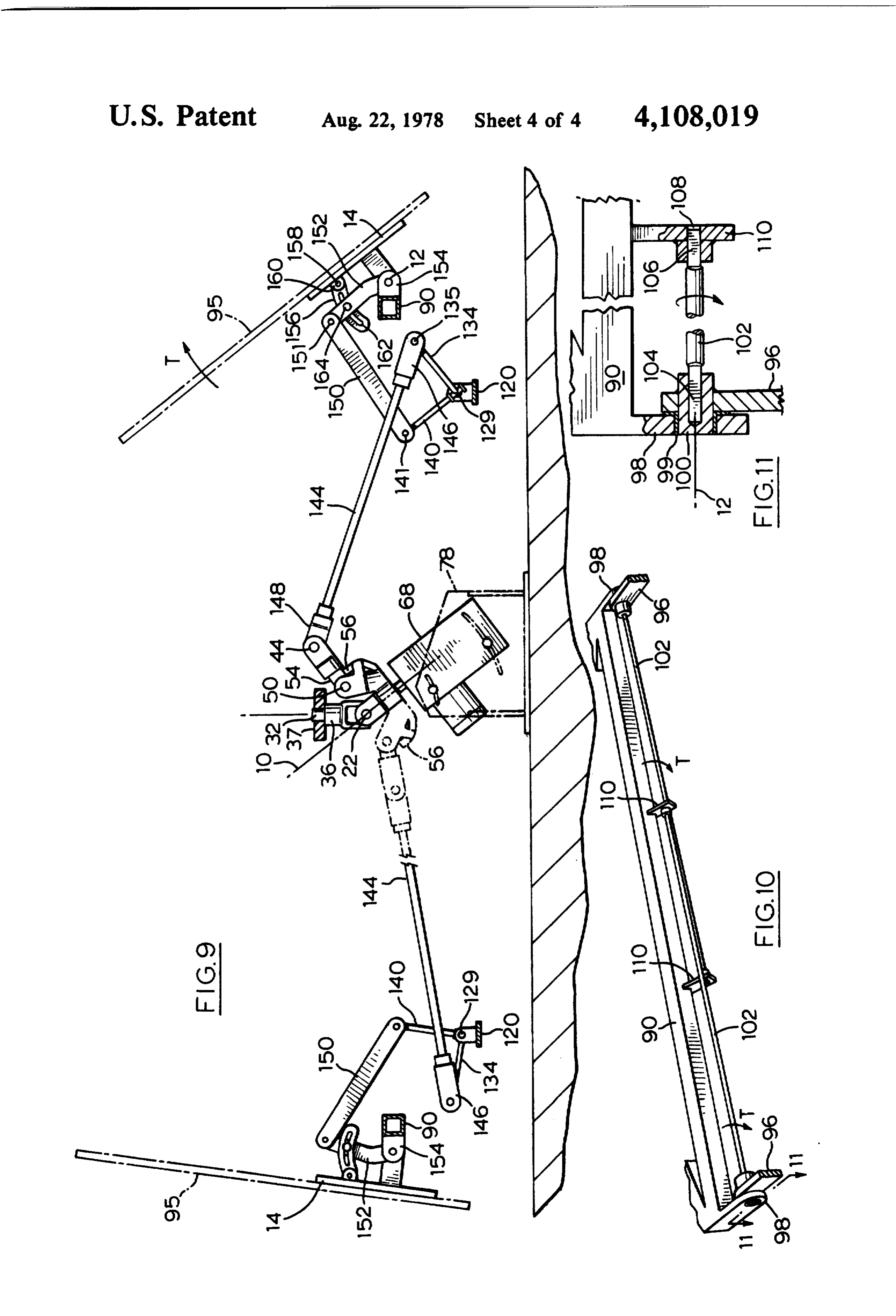
This invention relates to a solar tracking device. In intersection of said first axis and said first plane, the particular, this invention relates to a solar tracking de 5 driven member being arranged such that its variable vice suitable for maintaining the alignment of solar angular velocity is synchronized with respect to that of energy collector plates with the sun as the earth rotates. the sun about said second axis to track the sun in azi Various systems for tracking the sun as the earth muth, altitude drive means driving said tracking head rotates have previously been proposed. However, the about said third axis to track the sun in altitude as said drive mechanisms have been complex and expensive to O tracking head is driven about said centre of gyration. manufacture and maintain. With the increased interest According to a further aspect of the present inven in solar energy and the likelihood of solar energy being tion, the solar tracking device comprises a driving shaft widely used, both commercially and domestically, a having a first axis extending longitudinally thereof simple form of tracking device would serve to make about which it is rotationally driven at a constant speed, these devices more practical for general use. 15 said driving shaft being mounted with said first axis The apparent rotation of the sun about the earth as extending parallel to the axis of rotation of the earth, a observed from a point on the surface of the earth which frame mounted for rotation in azimuth in a first plane is spaced from the equitorial and polar regions of the which is angularly inclined with respect to said first earth is such that the position of the sun varies both in axis, said frame rotating about a second axis, a tracking azimuth and in altitude so that the drive mechanism 20 head mounted on said frame for altitudinal rotation must accommodate variations in two distinct planes. about a third axis which is disposed in said first plane Previous proposals have included an electronic control and which extends perpendicular to the azimuthal posi mechanism for controlling the rotational speed of the tion of the sun with respect to said second axis, altitude tracking device in azimuth and in altitude. Such devices drive means comprising a driving element mounted on would, however, be expensive to manufacture and 25 said driving shaft and extending radially therefrom for would require highly skilled maintenance mechanics in rotation about said first axis in an equitorial plane which order to service them. coincides with said first plane at said first axis whereby The present invention provides a simple mechanical its angle of inclination with respect to said first plane drive mechanism which serves to track the sun in azi varies in accordance with the variation and altitude of muth and in altitude. 30 the sun wich respect to said first plane and transmission I have recognized that the azimuthal rotation of the means connecting said driving element to said tracking sun about a point on the surface of the earth has an head to rotate said tracking head about said third axis to analog in the relationship of the angular rotation of the track the sun in altitude as said tracking head is driven driven member with respect to the driving member of a about said first axis, azimuthal drive means driving said common universal joint or Hookes joint. 35 frame about said second axis at a variable angular veloc The sun may be observed to rotate about a point on ity synchronized with respect to the velocity of the sun the surface of the earth in an equitorial plane extending about said second axis to track the sun in azimuth. from an axis extending parallel to the axis of rotation of According to a still further aspect of the present the earth. I have recognized that by mounting the track invention, a solar tracking device comprises a driving ing head so that it rotates in altitude about an axis which 40 shaft having a first axis extending longitudinally thereof is disposed in the first plane which intersects the axis of about which it is rotationally driven at a constant speed, rotation of the earth at its point of intersection with the said driving shaft being mounted with said first axis equitorial plane, the variation in angular inclination of a extending parallel to the axis of rotation of the earth, a radiant extending from the first axis in the equitorial frame mounted for rotation in azimuth in a first plane plane with respect to the first plane in the analog of the 45 which is angularly inclined with respect to said first variation in altitude of the sun with respect to the first axis, said frame rotating about a second axis, a tracking plane. By mounting an altitude drive member for rota head mounted on said frame for altitudinal rotation tion in the equitorial plane about the axis of rotation about a third axis which is disposed in said first plane parallel to the axis of the earth, I can provide an altitude and which extends perpendicular to the azimuthal posi drive mechanism which will track the movement of the 50 tion of the sun with respect to said second axis, azi sun in altitude. muthal drive means and altitude drive means each
SUMMARY OF INVENTION
driven by said driving shaft and having a common cen tre of gyration located in said first plane and on said first
According to one aspect of the present invention, the axis, said azimuthal drive means including a universal solar tracking device comprises a driving shaft having a 55 joint having; a driving member connected to said driv first axis extending longitudinally thereof about which it ing shaft for rotation about said first axis in an equitorial is rotationally driven at a constant speed, said driving plane and a driven member connected to said frame for shaft being mounted with said first axis extending paral rotation in said first plane about said second axis and a lel to the axis of rotation of the earth, a frame mounted centre of gyration coincident with said common centre for rotation in azimuth in a first plane which is angularly of gyration, the driven member being arranged such inclined with respect to said first axis, said frame rotat that its variable angular velocity is synchronized with ing about a second axis, a tracking head mounted on that of the sun about said second axis to track the sun in said frame for altitudinal rotation about a third axis azimuth, said altitude drive means including a driving which is disposed in said first plane and which extends element mounted on said driving ahsft and extending perpendicular to the azimuthal position of the sun with 65 radially therefrom for rotation about said first axis in respect to said second axis, azimuthal drive means com said equitorial plane whereby its angle of inclination prising a universal joint having a driving member con with respect to said first plane varies in accordance with nected to said driving shaft for rotation about said first the variation in altitude of the sun with respect to said
Page 7
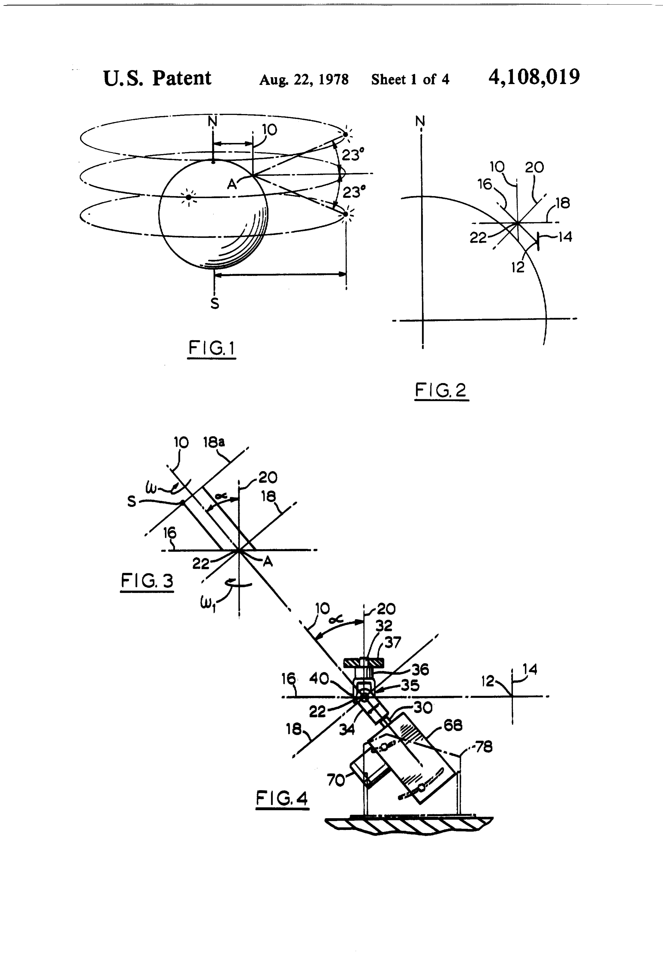
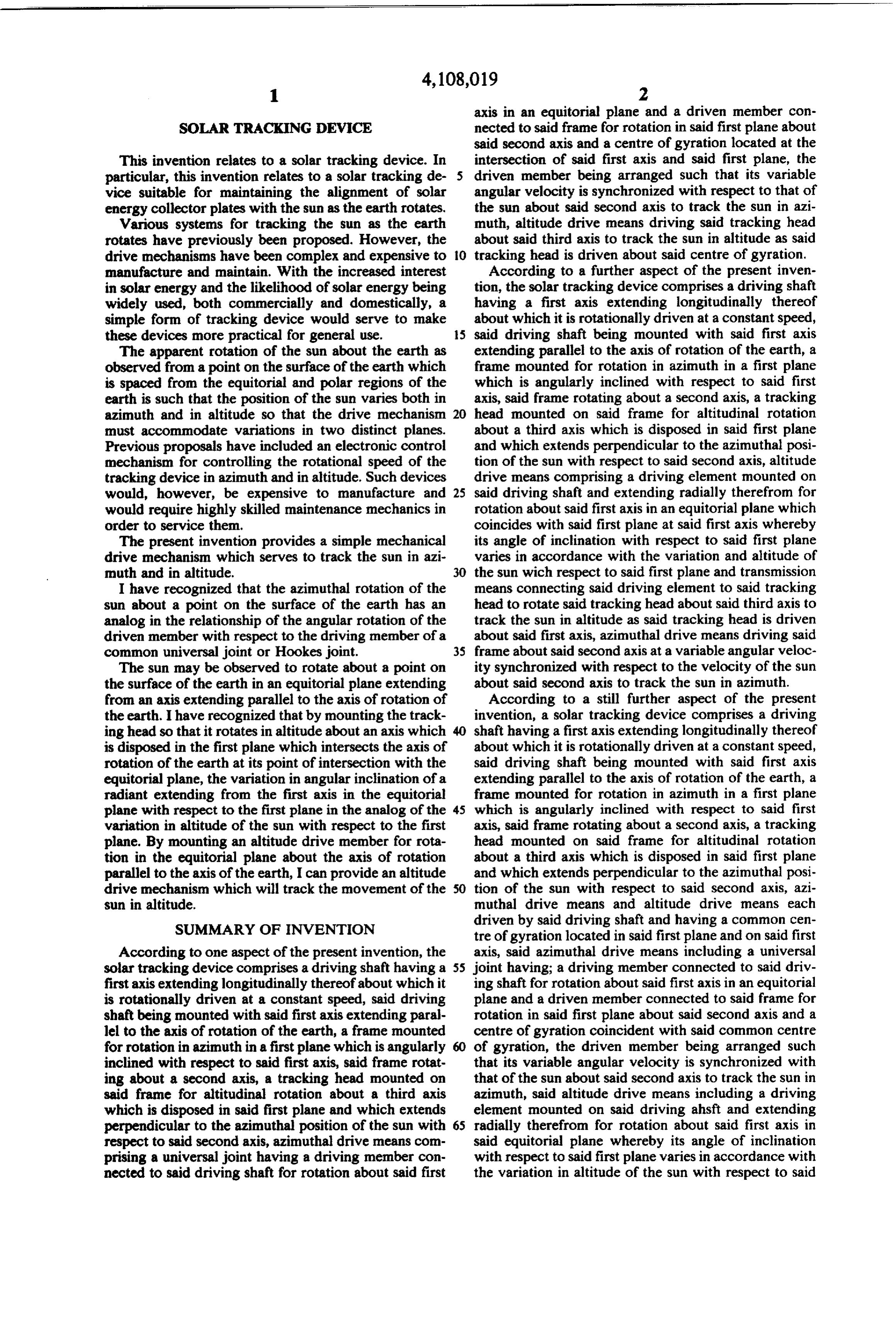
first plane, and transmission means connecting said driv S rotates in an equitorial plane parallel to the equitorial ing element to said tracking head to rotate said tracking plane 18 and in FIG. 3 this plane is identified as plane head about said third axis to track the sun in altitude as 18a. The angular velocity of the sun about the first axis said tracking head is driven about said centre of gyra 10 is a constant one revolution per day, whereas the tion. observed angular velocity at the point A about the The invention will be more clearly understood after second axis 20 is variable and may be identified as o. reference to the following detailed specification read in If the sun S is considered to turn through an angle 6 conjunction with the drawings, wherein about the first axis 10 in the equitorial plane 18 at a FIG. 1 of the drawings diagrammatically illustrates velocity (), then the apparent velocity co about the the apparent motion of the sun about a point on the 10 vertical axis 20 may be determined by the formula surface of the earth;
FIG. 2 diagrammatically illustrates the position of the a)/o = (1-cos'8sina)/cosa.
various planes and axes described in the remainder of the specification in relation to the surface of the earth; wherein
FIG. 3 diagrammatically illustrates the azimuthal 15 8 = angle of rotation of the sun in equitorial plane, rotation of the sun about an axis parallel to the axis of a = angle of inclination of axis of the earth with rotation of the earth; respect of vertical plane FIG. 4 is a side view of the azimuthal drive mecha c) = angular velocity of the sun in equitorial plane, nism; a) = observed angular velocity of the sun in horizon FIG. 5 diagrammatically illustrates the altitude drive 20 tal plane.
mechanism; As previously indicated, I have recognized that the FIG. 6 is a side view of the mechanism which origi relationship between the angular velocity of the driving nates the altitude drive; shaft and that of the driven shaft of a common universal FIG. 7 is a pictorial view of a solar tracking device or Hookes joint is identical to the apparent angular according to an embodiment of the present invention; 25 velocity of the sun about an axis parallel to the axis of FIG. 8 is a pictorial view of a portion of the altitude rotation of the earth and the observed velocity in a drive mechanism; plane of azimuth which is angularly inclined with re FIG. 9 is a side view of the tracking mechanism of spect to the axis of rotation of the earth. It is well estab FIG. 8; lished that the ratio of angular velocity of the driving FIG. 10 is a pictorial view of a torsion bar mechanism 30 shaft with respect to the angular velocity of the driven for applying torsion to the tracking head, and shaft of a common universal joint may be determined by FIG. 11 is a detailed view of the torsion bar mecha the formula nism of FIG. 10.
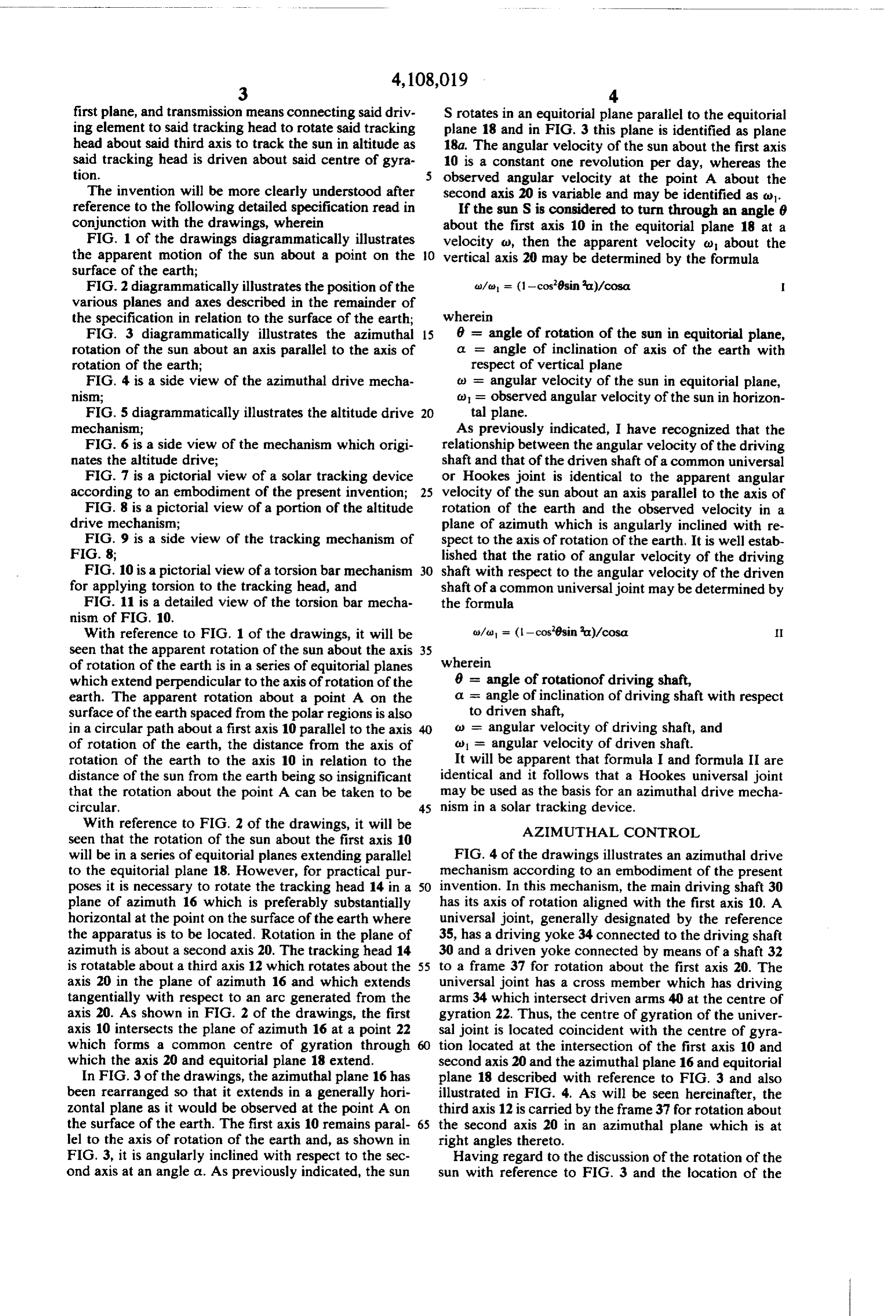
With reference to FIG. 1 of the drawings, it will be o/a) = (1-cos'8sina)/cosa II seen that the apparent rotation of the sun about the axis 35 of rotation of the earth is in a series of equitorial planes wherein which extend perpendicular to the axis of rotation of the 8 = angle of rotationof driving shaft, earth. The apparent rotation about a point A on the a = angle of inclination of driving shaft with respect surface of the earth spaced from the polar regions is also to driven shaft, in a circular path about a first axis 10 parallel to the axis 40 c) = angular velocity of driving shaft, and of rotation of the earth, the distance from the axis of c) = angular velocity of driven shaft. rotation of the earth to the axis 10 in relation to the It will be apparent that formula I and formula II are distance of the sun from the earth being so insignificant identical and it follows that a Hookes universal joint that the rotation about the point A can be taken to be may be used as the basis for an azimuthal drive mecha circular. 45 nism in a solar tracking device. With reference to FIG. 2 of the drawings, it will be AZIMUTHAL CONTROL seen that the rotation of the sun about the first axis 10 will be in a series of equitorial planes extending parallel FIG. 4 of the drawings illustrates an azimuthal drive to the equitorial plane 18. However, for practical pur mechanism according to an embodiment of the present poses it is necessary to rotate the tracking head 14 in a 50 invention. In this mechanism, the main driving shaft 30 plane of azimuth 16 which is preferably substantially has its axis of rotation aligned with the first axis 10. A horizontal at the point on the surface of the earth where universal joint, generally designated by the reference the apparatus is to be located. Rotation in the plane of 35, has a driving yoke 34 connected to the driving shaft azimuth is about a second axis 20. The tracking head 14 30 and a driven yoke connected by means of a shaft 32 is rotatable about a third axis 12 which rotates about the 55 to a frame 37 for rotation about the first axis 20. The axis 20 in the plane of azimuth 16 and which extends universal joint has a cross member which has driving tangentially with respect to an arc generated from the arms 34 which intersect driven arms 40 at the centre of axis 20. As shown in FIG. 2 of the drawings, the first gyration 22. Thus, the centre of gyration of the univer axis 10 intersects the plane of azimuth 16 at a point 22 sal joint is located coincident with the centre of gyra which forms a common centre of gyration through tion located at the intersection of the first axis 10 and which the axis 20 and equitorial plane 18 extend. second axis 20 and the azimuthal plane 16 and equitorial In FIG. 3 of the drawings, the azimuthal plane 16 has plane 18 described with reference to FIG. 3 and also been rearranged so that it extends in a generally hori illustrated in FIG. 4. As will be seen hereinafter, the zontal plane as it would be observed at the point A on third axis 12 is carried by the frame 37 for rotation about the surface of the earth. The first axis 10 remains paral 65 the second axis 20 in an azimuthal plane which is at lel to the axis of rotation of the earth and, as shown in right angles thereto.
FIG. 3, it is angularly inclined with respect to the sec Having regard to the discussion of the rotation of the ond axis at an angle a. As previously indicated, the sun sun with reference to FIG. 3 and the location of the
Page 8
universal joint with reference to FIG, 4, it will be seen very gradually and consequently this adjustment may that if the driven arms 40 of the driven yoke 36 of the be made manually on a week by week or month by universal joint are oriented to extend in the plane of month basis or a small correcting drive mechanism may azimuth 16 perpendicular to the third axis 12 and the be provided in combination with a sensing head driving shaft 30 is rotatably driven at a speed of one 5 mounted on the detector head 14. revolution per day, the angular velocity of the third axis While FIG. 5 of the drawings serves to illustrate the 12 about the second axis 20 may be synchronized with principle upon which the altitude drive mechanism of respect to the apparent angular velocity of the sun the present invention operates, a mechanism con about the axis 20 so that the tracking head 14 may be structed in accordance with FIG. 5 would tend to lock aligned with the sun and caused to track the sun's rota 10 when it approaches the position 90 removed from that tion in azimuth. shown in FIG. 5 in which the pivot points 44 and 49 ALTITUDE CONTROL would be located in the plane of azimuth 16 and the detector 14 would extend perpendicularly with respect
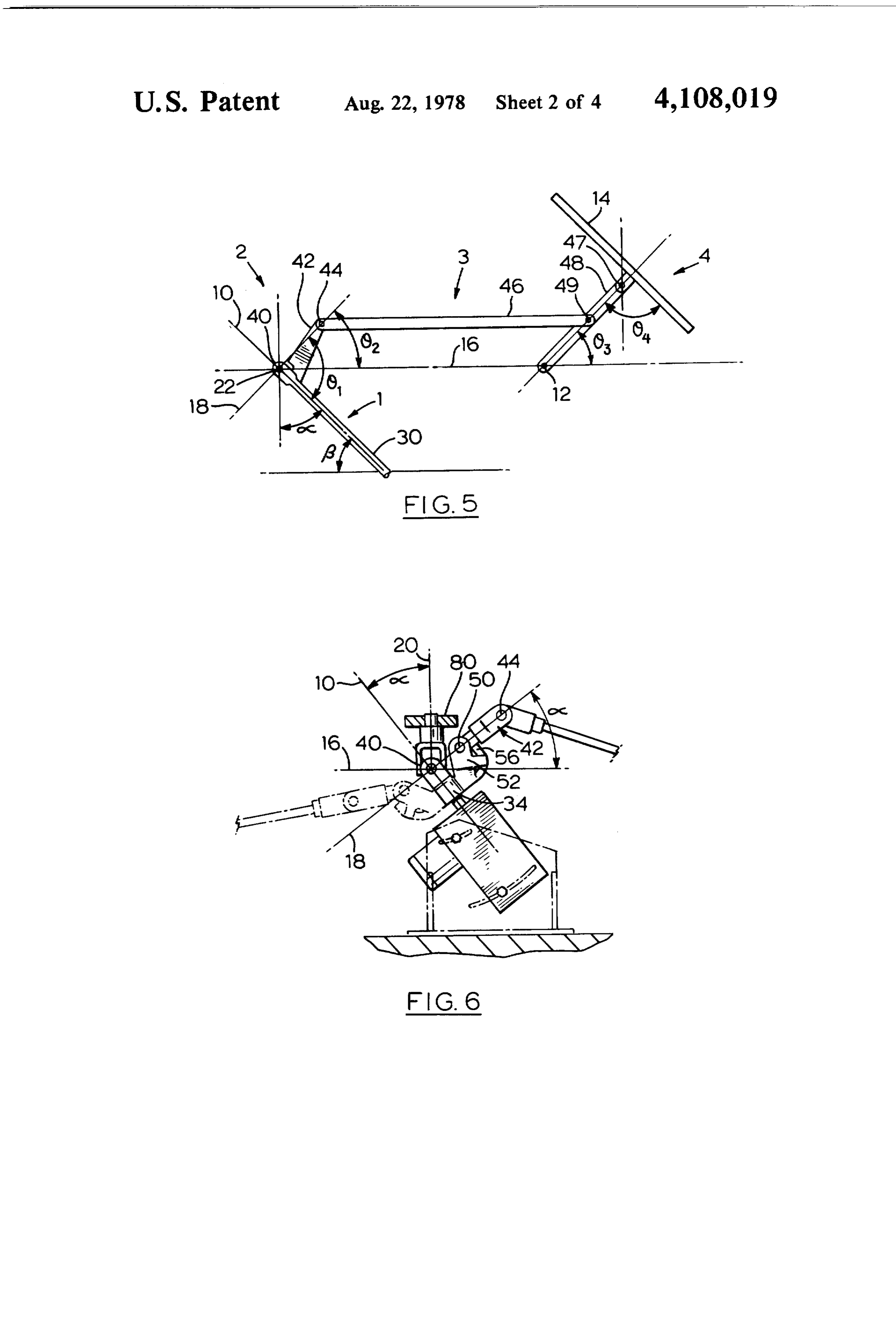
FIG. 5 of the drawings diagrammatically illustrates to the plane of azimuth 16. In addition, movement be the principle on which the altitude control mechanism 15 yond this point would cause the detector head to tilt operates. In FIG. 5, like numerals have been applied to forward beyond the perpendicular position and it like axes, planes and parts previously described with would eventually be directed downwardly in attempt reference to FIGS. 1 to 4 of the drawings. In FIG. 5, a ing to track the sun after sunset. Tracking of the sun driving arm 42 projects radially outwardly from the after sunset is obviously unnecessary and consequently first axis 10 and has a pivot point 44 at the outer end 20 the altitude of the tracking head after sunset is immate thereof which is located in the equitorial plane 18 such rial. However, in order to permit the driving shaft 30 to that upon rotation of the driving shaft 30, the pivot rotate continually at a uniform rotational speed of one point will remain in the equitorial plane 18 for all posi revolution per day it is necessary to continue the rota tions of the arm 42. It will be noted that, when viewed tion of the tracking head in azimuth after sunset. along axis 10, the arm 42 is radially aligned with the 25 While various mechanisms may be employed to pro driven arm 40 of the universal joint 35 previously de vide a lost motion in the link arm 46 of FIG. 5 to pre scribed with reference to FIG. 4. This fact is important vent the inversion of the parallelogram drive linkage, in synchronizing the operation of the azimuthal and one particularly convenient mechanism is described altitude drive mechanisms as will be described hereinaf with reference to FIGS. 7 to 9 of the drawings hereinaf ter. 30 ter.
It will be apparent that upon rotation of the driving FIG. 6 of the drawings illustrates a practical form of shaft 30, the angle of inclination 6 of the plane in which the driving arm 42 incorporating a component which the arm 42 is located will vary from -- a to -o and will will provide the required lost motion. Again, in FIG. 6 be zero when the arm 42 has rotated through 90' about of the drawings like numerals apply to like axes, planes the first axis 10. This change in angular inclination of 35 and parts previously described with reference to FIGS. the arm 42 with respect to the azimuthal plane 16 occurs 1 to 5. The lost motion mechanism includes a bracket 52 at a rate corresponding to the rate of change in altitude which supports a shaft 50 upon which arm 54 is pivot of the sun observed in the azimuthal plane. Conse ally mounted. A stop 56 formed on the bracket 52 serves quently if this motion is translated to the detector head to prevent angular rotation of the shaft 54 below the 14, the detector head 14 can be made to rotate about the 40 equitorial plane 18 so that the pivot pin 44 located at the axis 12 to track the sun in altitude. In the diagrammatic outer end of the shaft 54 cannot extend below the illustration in FIG. 5 of the drawings, the power is equitorial plane 18. The pivot pin 44 can, however, be transmitted to the tracking head by a parallelogram displaced angularly above the equitorial plane and does linkage mechanism which includes a link arm 48 which so when the pivot point 50 passes below the plane of is pivoted at one end on the third axis 12 and is con 45 azimuth 16 in response to rotation of the driving shaft nected at its other end to the tracking head 14 and an 34.
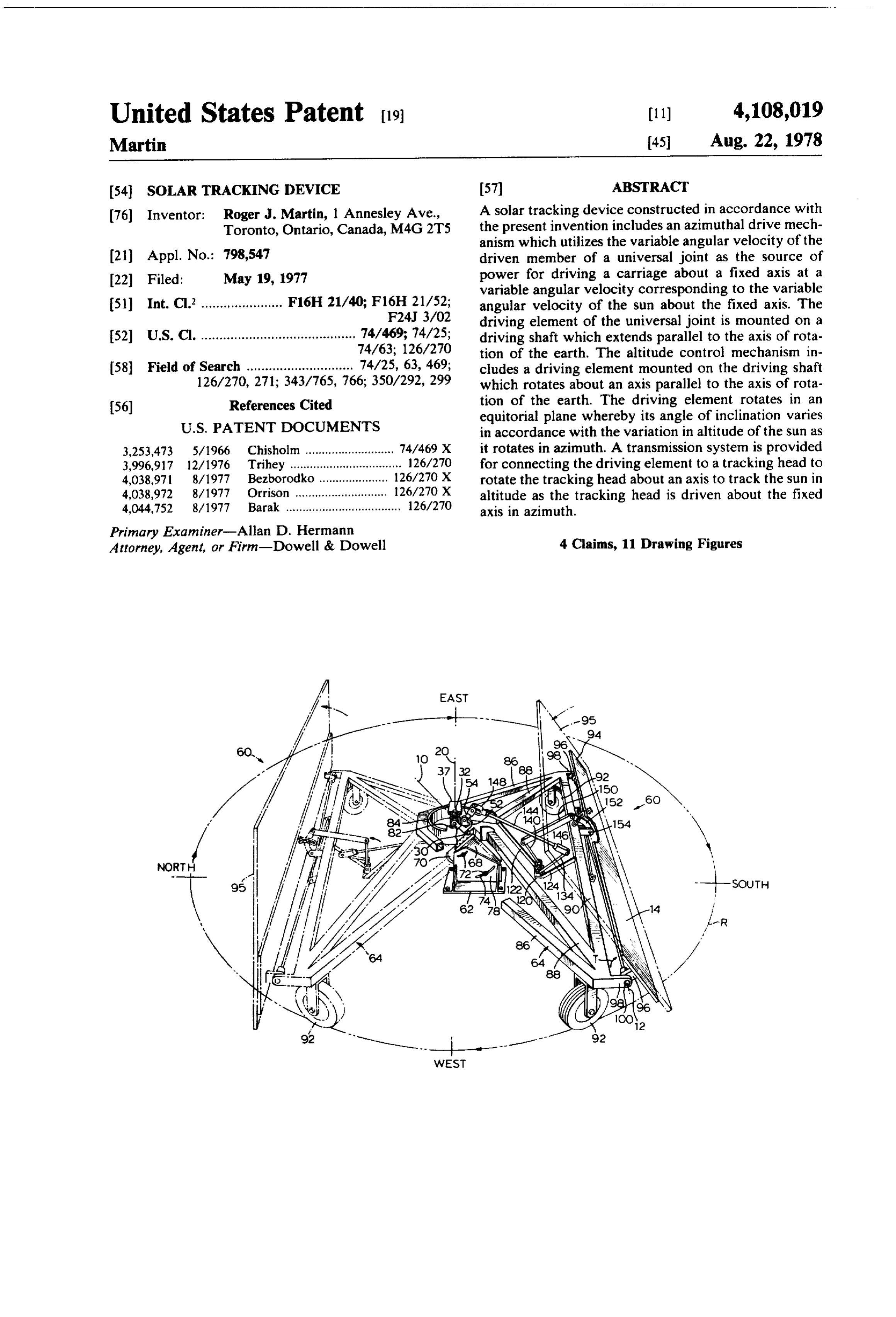
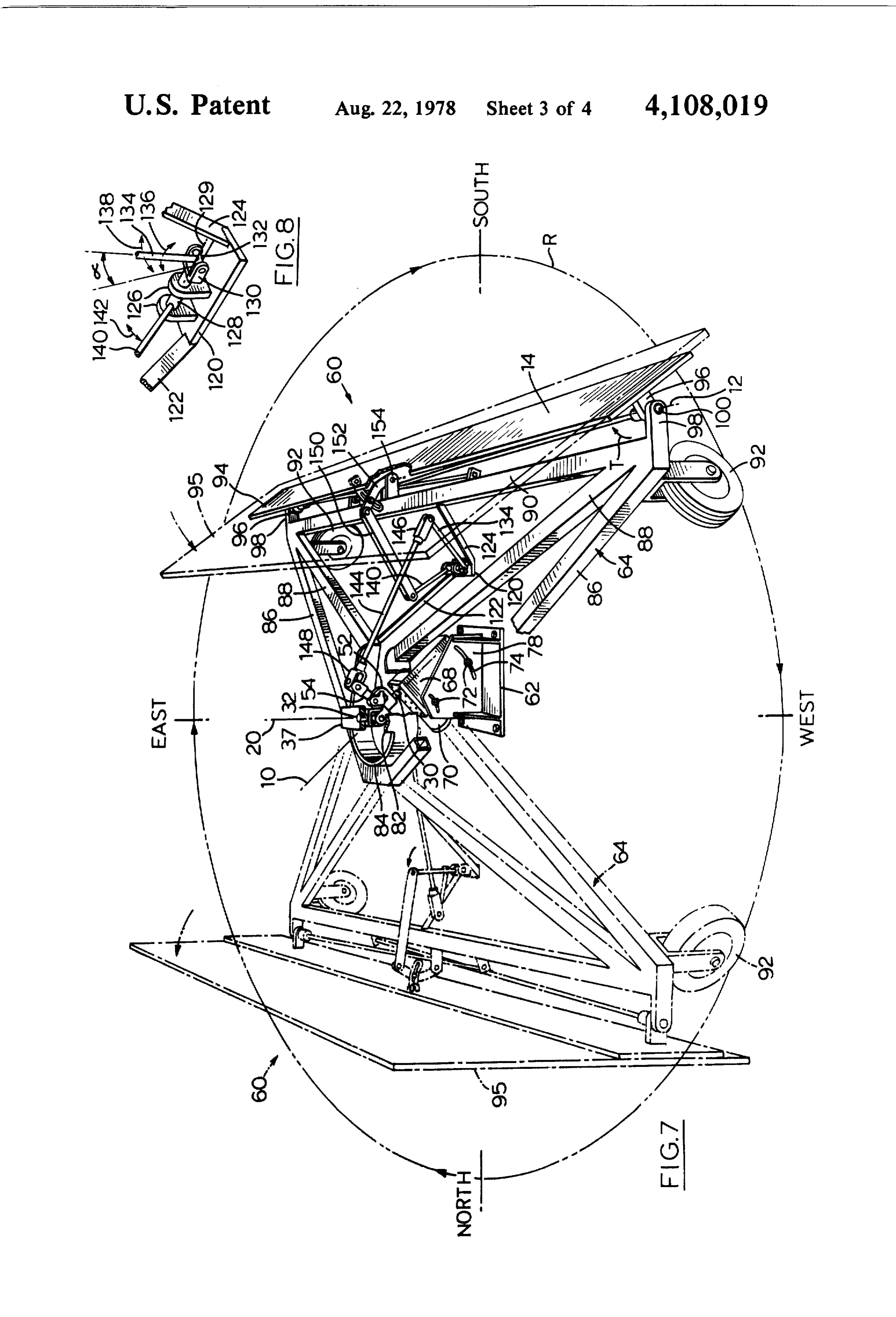
intermediate link arm 46. The intermediate link arm 46 In FIG. 7 of the drawings, the reference numeral 60 is connected to the pivot pin 44 at one end and to a pivot refers generally to a solar tracking device constructed pin 49 at the other end. The pivot pin 49 is located in accordance with a preferred embodiment of the pres radially outwardly from the third axis 12 a distance 50 ent invention. The device includes a base member 62, a equal to the radial displacement of the pivot pin 44 with carriage 64 and a tracking head 14. respect to the first axis 10 and the link arm 46 has a A drive unit 68 having a drive motor 70 is mounted in length equal to the distance between the centre of gyra the base 62 by means of a pair of mounting studs 72 tion 22 and the third axis 12 measured in the azimuthal which extend through arcuate passages 74 formed in plane 16. Thus, it will be seen that 6, may equal 6s for 55 oppositely disposed side plates 78 of the base. The main all positions of the driving arm 42. driving shaft 30 is rotatably driven by the drive unit 68. As shown in FIG. 1 of the drawings, the equitorial The arcuate shaped slots 74 in the base serve to permit plane of the sun during the summer and winter is angu the drive unit 60 to be angularly adjusted with respect larly displaced at an angle of 23 with respect to the to the base 62 to align the first axis 10 of the driving equitorial plane at the equinox. Thus, it is only at the 60 shaft 30 with respect to the axis of rotation of the earth equinox condition that the equitorial plane extends at any required location. The drive unit 68 includes a through the centre of gyration 22. Nevertheless, it is reduction gear mechanism for reducing the rotational possible to compensate for the variation in the position speed of the motor 70 to drive the driving shaft 30 at a of the equitorial plane by adjusting the angle 8, which rotational speed of one revolution per day. The frame is the angle of inclination of the tracking head 14 with 65 or carriage 64 has a cross bar 37 which is mounted on respect to the support linkage 48. The angle of inclina the driven shaft 32 of the universal joint as previously tion 64 may be adjusted by pivoting the head 14 about described with reference to FIG. 4 of the drawings so a pivot point 47. The change in equitorial plane occurs that the frame 64 may be rotated in azimuth to follow
Page 9
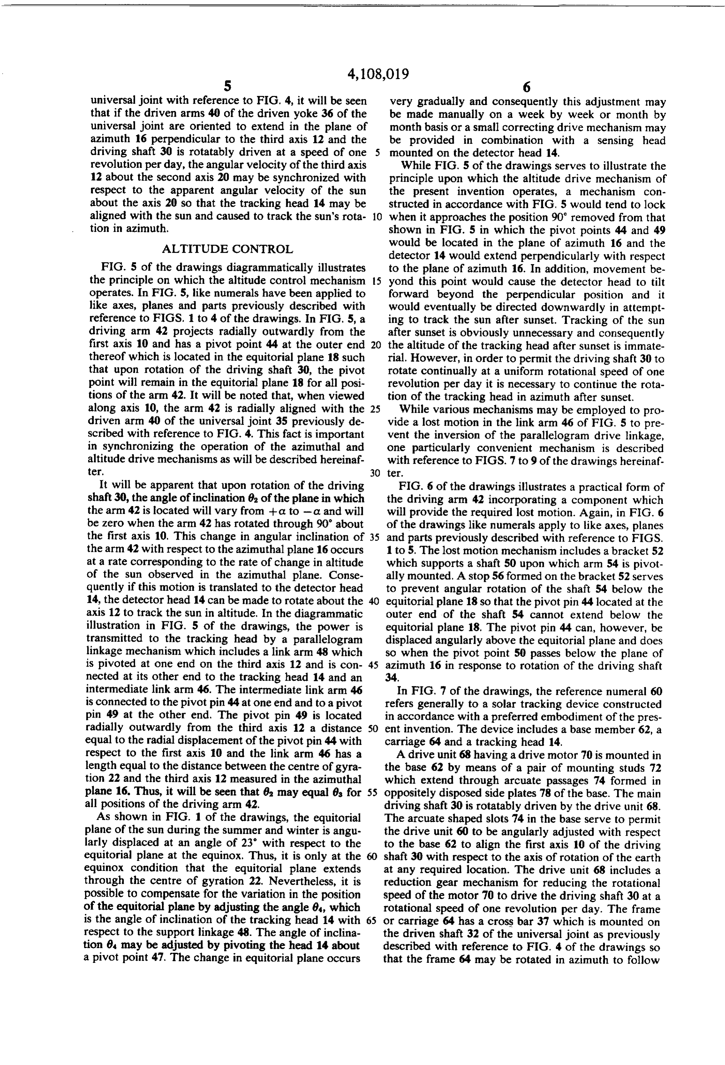
the azimuthal rotation of the sun about the second axis frame 64 by arms 122 and 124 which are connected to 20. beams 88 and 90 respectively. As shown in FIG. 7 of the The cross bar 37 extends transversely between a pair drawings, a pair of lugs 126 are mounted on the plate of arms 82 (only one shown) which project upwardly 120 and project upwardly therefrom. A shaft 128 is from a collar 84. The collar 84 is spaced outwardly from mounted for rotation about the axis 129 on lugs 126. A the first axis 10 a distance sufficient to provide clearance yoke 130 is located at one end of the shaft 128 and a for the altitude drive mechanism as it is rotatably driven shaft 132 is pivotally mounted on the yoke 130 for rota about the first axis 10. The collar 84 is secured as by tion in the direction of the arrows 136. A lever arm 134 welding to box frame members 86 and 88 which project projects radially outwardly from the shaft 132 so as to outwardly therefrom and are connected at their outer 10 be rotatable in the direction of the arrows 138 about the ends to a transverse box-shaped beam 90. Tracking axis 129. A lever arm 140 projects radially from the wheels 92 are mounted on the frame 64 at the outer shaft 128 and is rotatable about the axis 129 in the direc extremities thereof and are oriented to track along an tion of the arrows 142. Lever arms 134 and 140 are arc generated from the axis 20. The tracking wheels 92 connected to one another as previously described to and the base 62 serve to support the carriage 64. 15 provide a bell crank lever mechanism. The lever arm The tracking head 14 consists of a rectangular-shaped 134 has a yoke 146 at one end thereof connected to link plate 94 which supports a sensor array 95. A pair of lugs arm 144 which has a shaft 148 at the other end thereof 96 project rearwardly from the plate 94 and a pair of connected to shaft 54 along axis 44. Thus, it will be seen lugs 98 projecteforwardly from the beam 90. As shown that the bell crank mechanism and link arm 144 cooper in FIG. 11 of the drawings, the stub shaft 100 is secured 20 ate to provide a first parallelogram having axes 22, 44, to the lugs 96 and is pivotally mounted in a bush 99 135 and 129.
carried by lugs 98. The stub shaft 100 has its axis of the lever arm 140 is pivotally connected along axis rotation aligned with the third axis 12 so that the detec 141 to link arm 150 which is pivotably connected along tor head 14 may pivot about the axis 12 relative to the axis 151 to arm 152 which is in turn pivotably connected frame 64. For reasons described hereinafter, it is desir 25 to the frame along axis 12. Thus, the second parallelo able to spring-load the detector head 14 so that it is gram linkage has arms pivotably connected at axes 129, urged to rotate about the axis 12 in the direction of the 141, 151 and 12. Brackets 154 project rearwardly from arrow T. This bias serves to maintain the arm 54 in the the beam member 90 to support the pivot pin which position bearing against the stop 56 during twelve hours provides the connection with the arm 152 on axis 12. of rotation of the altitude drive mechanism, 30 As previously indicated, it is necessary to make peri Biasing of the tracking head 14 in the direction of the odic adjustments of the angular position of the tracking arrow T is obtained by means of a torsion bar mecha head about the axis 12 as the equitorial plane of rotation nism illustrated in FIGS. 10 and 11 of the drawings. A of the sun changes. An arcuate-shaped bracket 156 has pair of torsion bars 102 each have a square-shaped end one end pivotally mounted on a pivot pin 158 carried by 104 anchored in a square-shaped passage formed in the 35 lugs 160 which project rearwardly from the plate 94. shafts 100. The opposite ends 106 of the shafts are also The arcuate-shaped bracket 156 has an arcuate-shaped square and are mounted in a square-shaped passage 108 slot 162 extending longitudinally thereof in an arc gen in a lug 110 which projects outwardly from the trans erated about the third axis 12. A releasable mounting verse beam member 90, Torque is applied to the torque bolt assembly 164 releasably secures the arcuate-shaped bars 102 before they are mounted so that in use the 40 bracket 156 with respect to the arm 152. By releasing torsion bars 102 apply a torque in the direction of the the mounting bolt assembly 164, the angle of inclination arrow T about the axis 12. of the plane of the collector plate 194 may be adjusted As previously indicated, the altitude control mecha relative to the altitude control mechanism. nism illustrated in FIG. 6 of the drawings has practical INITIAL ALIGNMENT OF APPARATUS restrictions which would limit its application. The prac 45 tical form of altitude control mechanism illustrated in As previously indicated, in order to synchronize the FIGS. 7, 8 and 9 of the drawings does, however, func azimuthal rotation of the carriage with respect to the tion in exactly the same manner as that previously de sun, it is necessary to align the driven arms 40 of the scribed in FIG. 6 of the drawings during 180' of azi universal joint with the position of the sun in azimuth muthal rotation, plus or minus 90 from the position 50 and to ensure that the third axis 12 is located in the shown in FIG. 6. azimuthal plane and extends at right angles to the axis With reference to FIGS. 6 and 9 of the drawings, it extending through the driven arms of the universal will be seen that the simple parallelogram linkage mech joint. Similarly the altitude drive arm which projects anism of FIG. 6 has been replaced by a linkage mecha radially from the first axis 10 must be aligned with the nism which incorporates two parallelograms intercon 55 driven arms 44 of the universal joint and located in the nected by a bell crank. This mechanism has been em equitorial plane 18. In the position shown in FIG. 9 of ployed so that the arm 54 will pull the altitude control the drawings, the azimuthal and altitude drive mecha linkage when moving the detector head from the up nisms are arranged in the position which they are re right position which it will assume at sunrise and sunset quired to assume at noon and the angular position of the and its rearwardly inclined position which it will as 60 tracking head is adjusted so as to extend perpendicular sume at noon. This provides for the most efficient oper to the rays of the sun by adjustment of the position of ation of the linkage mechanism when translated to the the plate 94 about the third axis 12 by means of the tracking head through the second parallelogram link adjustment screw 164 and arcuate slot 162 previously age. described. At the equinox, the plate 94 will extend in a The altitude control mechanism will now be de 65 plane parallel to the first axis while under summer con scribed in detail with reference to FIGS. 7, 8 and 9 of ditions, the angle of inclination of the plate will increase the drawings. As shown in FIGS. 7 and 8 of the draw progressively in an anticlockwise direction about the ings, a plate 120 is supported in a position below the axis 12 up to an angle of 23 and in winter, the angle of
Page 10
inclination of the plate will be decreased progressively (b) a main driving shaft having a longitudinal first in a clockwise direction up to 23 from the position axis, said main drive shaft being mounted on said shown in FIG. 9. base for rotation about said first axis and being METHOD OF OPERATION 5 supported with said first axis extending parallel to the axis of rotation of the earth, said main drive
Having set the position of the solar tracking mecha shaft having a power output end, nism as described above, it is merely necessary to start (c) drive means connected to said main drive shaft for the driven motor 70 to rotate the driving shaft 30 about rotatably driving it about said longitudinal axis at the first axis 10 and the azimuthal and altitude drive one revolution per day, mechanisms will cause the tracking head to follow the 10 (d) a carriage supported for azimuthal rotation, in a sun as it rotates about the axis of the earth. During 24 first plane which is angularly inclined with respect hours of rotation, the azimuthal drive mechanism will to said first axis, about a second axis which extends maintain the third axis 12 in a plane normal to a line perpendicular to said first plane, extending from the sun to the centre of gyration 22. (e) a tracking head mounted on said carriage for alti During 12 hours, 6 hours before noon and 6 hours after 15 tudinal rotation about a third axis which is disposed noon, the altitude drive mechanism will maintain the in said first plane and spaced radially outwardly tracking head in the plane extending perpendicular to from said second axis and extends tangential to an the sun's rays. After the altitude control mechanism arc generated from said second axis, rotates past the 6 p.m. position, the arm 54 will begin to (f) azimuthal drive means comprising, pivot about pivot pin 50 so that the axis 54 will rise 20 (i) a universal joint having a centre of gyration, a above the equitorial plane 18. In this position, the track driving yoke, a driven yoke and a cross member, ing head will lean forward as shown in FIG. 9 of the said cross member having driving arms con drawings. A stop is, however, provided for limiting the nected to the driving yoke and driven arms con forward movement of the head so that it cannot tilt nected to the driven yoke, the driving arms and beyond the substantially vertical position shown to the 25 driven arms having axes extending perpendicular left in FIG. 9. Because this stop is provided, it is neces to one another and intersecting said centre of sary to provide for the shortening of one of the arms of gyration, the axis of the driven arms being ori the parallelogram. This is achieved by permitting the ented to extend perpendicular to said third axis, arm 54 to pivot upwardly about the pivot point 56 to the said driven yoke being connected to said main position shown in chain lines to the left of FIG. 9 so as 30 drive shaft and said driven yoke being connected to effectively shorten the distance between the pivot to said carriage with its axis of rotation aligned point 44a and the centre of gyration 22. with said second axis, such that rotation of said In the embodiment of the invention illustrated in main drive shaft drives said carriage about said FIGS. 7, 8 and 9, it will be seen that the first parallelo second axis at an angular velocity which varies gram of the altitude drive mechanism is oriented in a 35 in accordance with the azimuthal velocity of the generally vertical plane in the positions shown in FIGS. Sun, 7 and 9. When the frame is rotated to a position 90' (g) altitude drive means comprising, removed from that shown in FIG. 9, the first parallelo (i) an altitude drive arm projecting radially from gram will be slightly angularly inclined with respect to said main drive shaft and having a first point the vertical plane. This may introduce a minor error in 40 thereon which describes an arc in a second plane altitude adjustment of the tracking head. However, the which is perpendicular to said longitudinal axis error will be so minor as to be insignificant. of said main drive shaft and which intersects the Various modifications of the present invention will be longitudinal axis at a second point which is at the apparent to those skilled in the art without departing centre of gyration of said universal joint, said from the scope thereof. For example, the azimuthal 45 first point being oriented so that a line extending drive mechanism may be used to advantage in combina between said first point and said second point is tion with an alternative form of altitude drive mecha parallel to the rays of the sun at the equinox, nism and vice versa. In addition, an alternative form of (ii) linkage means extending between said first linkage mechanism for translating the altitude drive to point on said altitude drive arm and said tracking the tracking head may be provided while retaining the 50 head to maintain said tracking head at a fixed essential characteristics of the mechanisms illustrated in angle with respect to said line, FIGS. 5 and 9 of the drawings. (iii) means for adjusting the angular position of said In a further modification, the altitude adjustment in tracking head with respect to said linkage means the mechanism provided by the arcuate slot 162 and to alter said fixed angle in accordance with the clamping bolt assemblt 164 may be replaced by a pow- 55 declination of the sun.
ered drive mechanism controlled by a sensing head 2. A solar tracking device comprising, mounted on the detector head. The sensing head may (a) a driving shaft having a first axis extending longi serve to detect minor errors in the altitude position of tudinally thereof about which it is rotationally the head at a pre-set time each day or week, the detector driven at a constant speed, said driving shaft being head providing a signal which is directed to the drive 60 mounted with said first axis extending parallel to mechanism to cause the plate 94 to pivot about the axis the axis of rotation of the earth, 12 to correct the angle of inclination of the detector (b) a frame mounted for rotation in azimuth in a first head. plane which is angularly inclined with respect to These and other modifications of the present inven said first axis, said frame rotating about a second tion will be apparent to those skilled in the art. 65 axis,
What I claim as my invention is: (c) a tracking head mounted on said frame for altitu 1. A solar tracking device comprising, dinal rotation about a third axis which is disposed (a) a base member, in said first plane and which extends perpendicular
Page 11
to the azimuthal position of the sun with respect to equitorial plane and a driven member connected to said second axis, said frame for rotation in said first plane about said (d) azimuthal drive means and altitude drive means second axis and a centre of gyration located at the each driven by said driving shaft and having a intersection of said first axis and said first plane, the common centre of gyration located in said first 5 driven member being arranged such that its vari plane and on said first axis, able angular velocity is synchronized with respect (e) said azimuthal drive means including a universal to that of the sun about said second axis to track the joint having; a driving member connected to said sun in azimuth, driving shaft for rotation about said first axis in an (e) altitude drive means driving said tracking head equitorial plane and a driven member connected to 10 about said third axis to track the sun in altitude as said frame for rotation in said first plane about said said tracking head is driven about said centre of second axis and a centre of gyration coincident gyration.
with said common centre of gyration, the driven 4. A solar tracking device comprising, member being arranged such that its variable angu (a) a driving shaft having a first axis extending longi lar velocity is synchronized with that of the sun 15 tudinally thereof about which it is rotationally about said second axis to track the sun in azimuth. driven at a constant speed, said driving shaft being (f) said altitude drive means including a driving ele mounted with said first axis extending parallel to ment mounted on said driving shaft and extending the axis of rotation of the earth, radially therefrom for rotation about said first axis (b) a frame mounted for rotation in azimuth in a first in said equitorial plane whereby its angle of inclina 20 plane which is angularly inclined with respect to tion with respect to said first plane varies in accor said first axis, said frame rotating about a second dance with the variation in altitude of the sun with respect to said first plane, and transmission means axis, connecting said driving element to said tracking (c) a tracking head mounted on said frame for altitu head to rotate said tracking head about said third 25 dinal rotation about a third axis which is disposed axis to track the sun in altitude as said tracking head in said first plane and which extends perpendicular is driven about said centre of gyration. to the azimuthal position of the sun with respect to 3. A solar tracking device comprising, said second axis, (a) a driving shaft having a first axis extending longi (d) altitude drive means comprising a driving element tudinally thereof about which it is rotationally 30 mounted on said driving shaft and extending radi driven at a constant speed, said driving shaft being ally therefrom for rotation about said first axis in an mounted with said first axis extending parallel to equitorial plane which coincides with said first the axis of rotation of the earth, plane at said first axis whereby its angle of inclina (b) a frame mounted for rotation in azimuth in a first tion with respect to said first plane varies in accor plane which is angularly inclined with respect to 35 dance with the variation and altitude of the sun said first axis, said frame rotating about a second with respect to said first plane and transmission axis, means connecting said driving element to said (c) a tracking head mounted on said frame for altitu tracking head to rotate said tracking head about dinal rotation about a third axis which is disposed said third axis to track the sun in altitude as said in said first plane and which extends perpendicular 40 tracking head is driven about said first axis, to the azimuthal position of the sun with respect to (e) azimuthal drive means driving said frame about said second axis, said first axis at a variable angular velocity syn (d) azimuthal drive means comprising a universal chronized with respect to the velocity of the sun joint having a driving member connected to said about said second axis to track the sun in azimuth.
driving shaft for rotation about said first axis in an 45
Provenance
- Collection
- Cited prior art
- Original PDF
- patentimages.storage.googleapis.com →
- Filed
- 1977-05-19
- Pages
- 11
- Method
- pdftotext (the PDF's own text layer) + pdftoppm 300dpi page scans
- Source
- Google Patents bibliographic record
- Granted
- 1978-08-22
- Inventors
- Roger J. Martin
- Transcribed from
- patentimages.storage.googleapis.com →