patent · US5348629
Method and apparatus for electrolytic processing of materials
20 September 1994
Page 1 — bibliographic record
United States Patent (19) 11 Patent Number: 5,348,629 Khudenko 45 Date of Patent: Sep. 20, 1994 54 METHOD AND APPARATUS FOR 4,280,887 7/1981 Konstantouros .................... 204/150 ELECTROLYTIC PROCESSING OF 4,291,125 9/1981 Greatbatch ......................... 435/240 MATER ALS 4,421,616 12/1983 Bjune .................................. 204/115 4,619,745 10/1986 Porta et al. ......................... 204/151 76) Inventor: Boris M. Khudenko, 744 Moores Mill 4,702,806 10/1987 Miller et al. ....... . 204/106 Rd., Atlanta, Ga. 30327 4,707,226 11/1987 Dapperheld .......................... 204/8 21) Appl. No.: 650,936 OTHER PUBLICATIONS 22 Filed: Feb. 5, 1991 Khudenko, "Mathematical Models of Cementation Pro cesses' Aug. 1987 pp. 681-702. Journal of Environ.
Related U.S. Application Data Engineering.
(63) Continuation-in-part of Ser. No. 437,655, Nov. 17, Primary Examiner-John Niebling 1989, abandoned, and Ser. No. 492,651, Mar. 13, 1990. Assistant Examiner-Arun S. Phasge 51) Int. Cl. ................................................ CO2F 1/46 Attorney, Agent, or Firm--Needle & Rosenberg 52) U.S. C. .................................... 204/130; 204/131; 57 ABSTRACT
58) Field of Search ............... 204/149, 107, 109, 130, A method and apparatus for the electrochemical pro 204/140, 151, 78, 131 cessing of materials in which the material to be pro cessed is located within an electrolyte that is subjected 56 References Cited to strong local electromagnetic fields in a migrational
1,514,737 1/1924 Smith .................................. 204/150 electrokinetic forces capable of effecting the chemical 2,852,453 9/1958 Hausner ............... ... 204/131 and physical conversions in the materials to be pro 3,457,152 7/1969 Maloney, Jr. et al. ............. 204/131 cessed. This migrational transport layer can be induced 3,959,096 5/1976 Langer .................... ... 204/107 either by creating a cementation system, applying an 3,994,789 11/1976 Langer et al. ... ... 204/108 outside source of current to an electrode system, or a 4,004,993 1/1977 Horner et al. ... ... 204/131 combination of both.
4,028,199 6/1977 Holland ........... ... 204/109 4,035,269 7/1977 Mastrorilli ... 204/150 4,107,009 8/1978 Everett ................................ 204/129 48 Claims, 9 Drawing Sheets
CONVECTION
INBU KSOLUTION
PRIMARY
PARTICLE
Page 2
Drawing sheet — no readable text.
Page 3
Drawing sheet — no readable text.
Page 4
Drawing sheet — no readable text.
Page 5
Drawing sheet — no readable text.
Page 6
Drawing sheet — no readable text.
Page 7
Drawing sheet — no readable text.
Page 8
Drawing sheet — no readable text.
Page 9
Drawing sheet — no readable text.
Page 10
Drawing sheet — no readable text.
Page 11
METHOD AND APPARATUS FOR SUMMARY OF THE INVENTION
ELECTROLYTIC PROCESSING OF MATERIALS The present invention relates to a method and appara tus for electrochemically processing materials in which
BACKGROUND OF THE INVENTION 5 the particles of a material are contained within an elec This application is a continuation-in-part of the appli trolyte and are subjected to local electromagnetic cant's co-pending applications, Ser. No. 07/437/655, forces in a migrational transport layer, This migrational filed on Nov. 17, 1989 now abandoned and Ser. No. transport layer can be induced either by creating a ce 07/492,651, filed on Mar. 13, 1990. mentation system, applying an outside source of current The present invention relates to the class of electro 10 to an electrode system, or a combination of both, The chemical processes used for processing of materials in intensity of the local electromagnetic fields can be con electrolytes, particularly for the oxidation-reduction of trolled in various ways such as adding promoters, indif. organics, radically-induced dimerization and polymeri ferentions, complexing agents, or anions to the electro lyte; optimizing the mixing rate of the electrolyte; or zation, the coagulation and collection of mineral and 15 controlling organic suspended particles and emulsions, and the major activethe temperature of the electrolyte, The species in the migrational transport layer inactivation and killing of microorganisms. The method are hydrogen and hydride ions. The strength of the can be used in water and waste treatment industries, chemical, pharmaceutical, biochemical, food and other local electromagnetic fields within the migrational layer is sufficient to create short impulses of plasma and pro industries.
Electrochemical methods are often used for the 20 duce very substantial electroosmotic and electropho oxidation-reduction of organic and inorganic constitu retic forces,
Accordingly, it is an object of the present invention ents, coagulation, flotation, collection of charged parti cles in suspensions and emulsions, precipitation and cally to provide a method and apparatus for electrochemi crystallization, dimerization and polymerization, disin 25 greatlytreating materials wherein the process rate is fection and other processes. Various electrochemical inventionincreased. is to
Another objective of the present provide an electrochemical method for processes are described in literature sources including materials processing wherein specific induction means the following: for creating a migrational transport layer are used for controlling the process rate, yield and efficiency. Yet
Bockris, J. et al. (1981) Comprehensive Treatise of 30 another
Electrochemistry, Plenum Press, New York - Lon smaller apparatus objective is to reduce the process costs by using don and inexpensive reagents. Furthermore,
Levich, V. G., (1962) Physiochemical Hydrodynamics, vide an electrochemical it is an object of this invention to pro Prentice Hall, Englewood Cliffs, N.J. method of materials processing Jakovlev, S. V., Krasnoborodko, J. G., and Rogov, V. 35 local electromagnetic forces in aare in which the particles of material subjected to strong
M. (1987) Technology of electrochemical treatment layer. This migrational transport layer may betransport migrational induced of water, Publishing House Stroyizdat, Leningrad by the creation of a cementation system, the application (Russian). of current from an outside source, or both. Bard, A.J. and Faulkner, L. R., (1980) Electrochemical
Methods, Fundamentals and Applications, John tionMore to particularly, it is an object of the present inven provide a method and apparatus for electro
Wiley & Sons, New York, Chichester, Brisbane, Tor chemically processing materials in which a migrational OntO.
transport layer is induced by submerging a sacrificial
Hausner, T. K., U.S. Pat. No. 2,852,453, issued Sep. 16, metal in an aqueous electrolyte that contains a salt of a 1958, “Control of Cellulose Precipitation Bath Con second metal that is mere noble than the sacrificial centrations'. 45 metal. A further object of this invention is to increase Horner, D. E. et al., U.S. Pat. No. 4,004,993, issued Jan. the surface area of the cathode by connecting a ca 25, 1977, “Electrolytic Trapping of Iodine from Pro thodic material more noble than the sacrificial metal to cess Gas Streams'. the sacrificial metal. A still further object of this inven Maloney, T. N. et al., U.S. Pat. No. 3,457,152, issued tion is to submerge the sacrificial metal and the con Jul. 22, 1969, "Electrolytic Apparatus for Removing 50 nected cathodic material in separate compartments such Trace Metals'. that the sacrificial metal is submerged in a cementation Greatbatch, W., U.S. Pat. No. 4,291,125, issued Sep. 22, electrolyte and the cathodic material is submerged in an 1981, 'Method for Electronic Control of Infections aqueous electrolyte.
Using Silver Ions'. Furthermore, it is an object of the present invention However, none of these references describe the in 55 to provide a method and apparatus for the electrochem duction of a migrational layer using means such as a ical processing of materials in which an aqueous elec cementation system or high current density, or describe trolyte is brought into contact with an electrode system systems that inherently possess such migrational layer having at least one anode and at least one cathode and triggers, as used in the instant invention to efficiently a migrational transport layer is induced by applying a process various materials. Major disadvantages of the high current density to a cathode. The current can be existing electrochemical processes include the follow applied as direct current pulses. A further object of this ing: a low rate of material processing (typically from invention is to increase the intensity of the local electro 20-30 minutes to 3-10 hours); high energy consumption magnetic fields by applying a polarizing current to the caused mainly from side reactions such as evolution of electrode system to dialyze the electrolyte. hydrogen, oxygen, or chlorine; high consumption of 65 It is also an object of the present invention to provide reagents, such as acids or salts that are added in order to a method for electrochemically processing materials increase the electrolyte conductance and reduce energy through oxidation-reduction, dimerization and poly losses; and complex and expensive equipment. merization or coagulation processes, or through the
Page 12
collection and separation of suspensions and emulsions "indifferent ion' refers to an ion that does not partici or inactivation and/or destruction of microorganisms. pate in reactions at either the cathode or anode. Exam These and other objects and advantages of the pres ples of indifferent ions include, but are not limited to, ent invention are apparent to a person skilled in the art Lit, Na+, and K. A "complexing agent” refers to a from the following detailed description. 5 mineral or organic species that can complex with a metal to slow down the metal's rate of diffusion. Exam
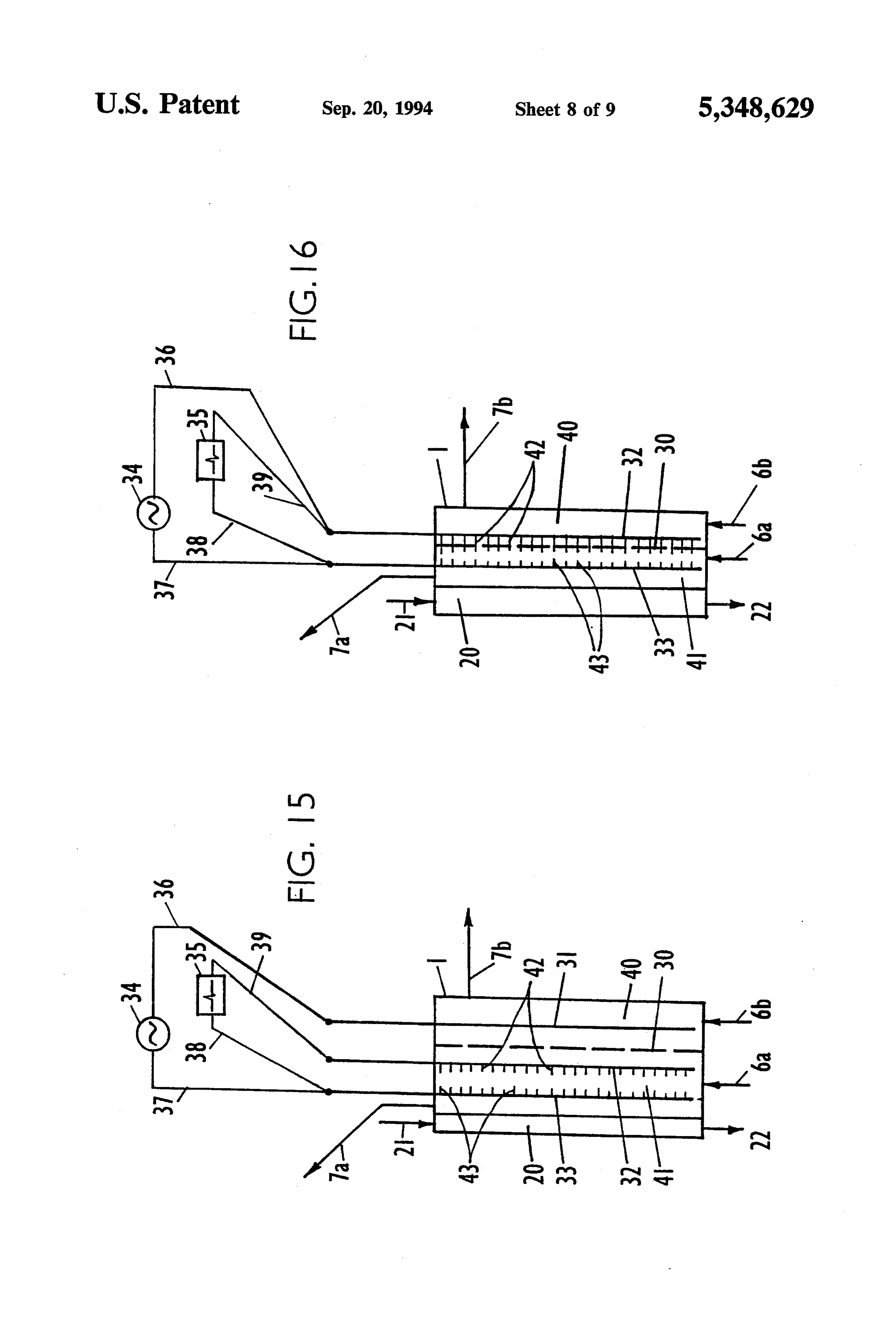
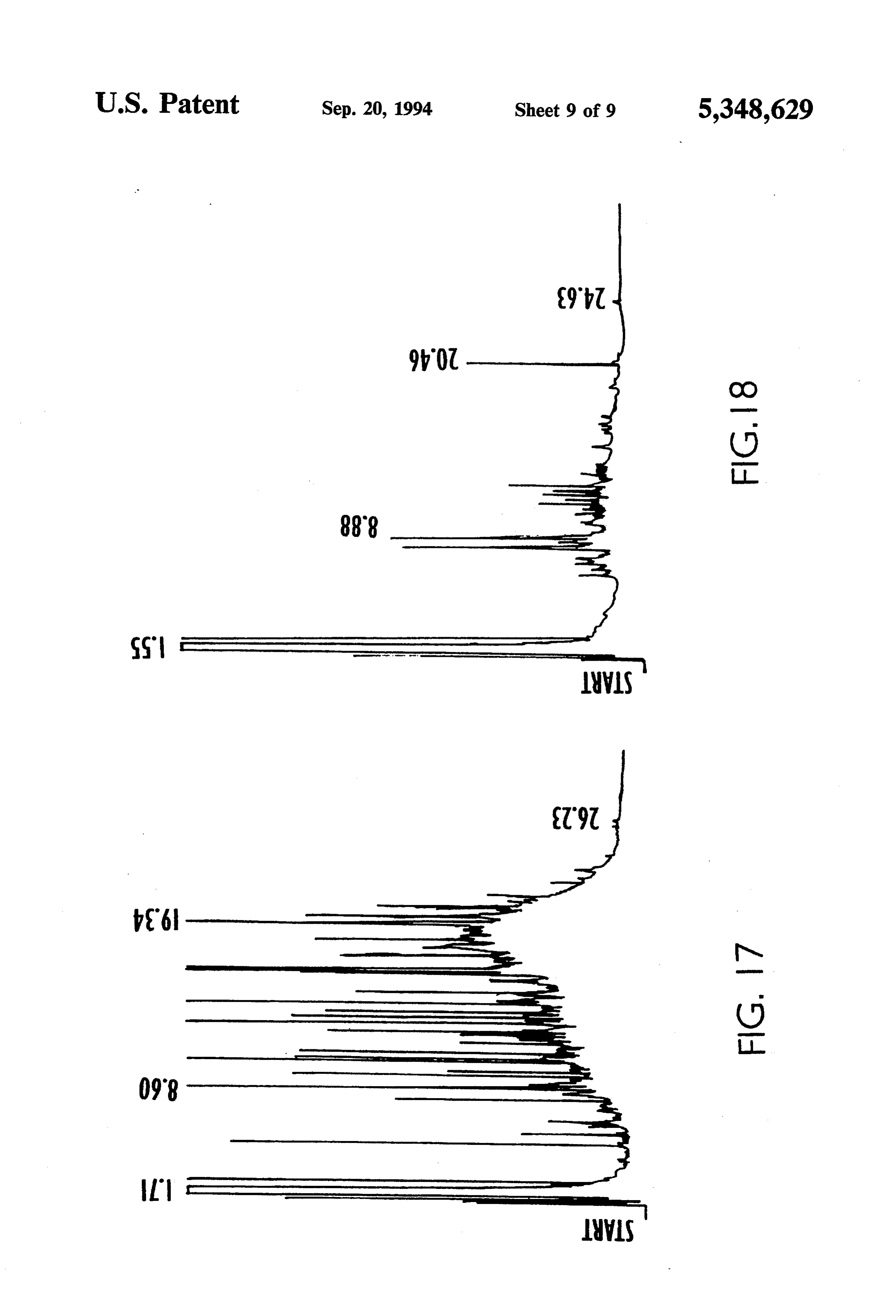
BRIEF DESCRIPTION OF DRAWINGS
ples of complexing agents include, but are not limited
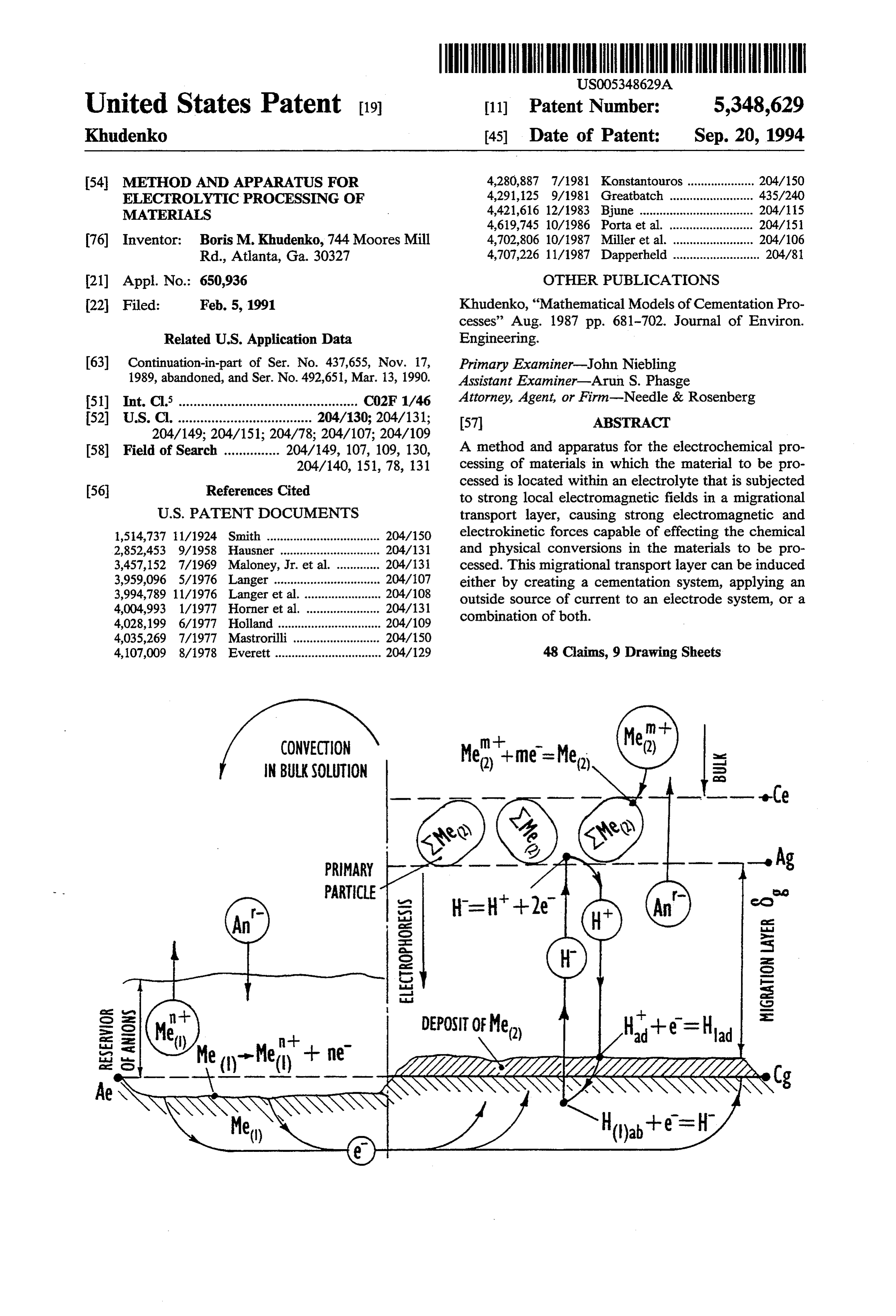
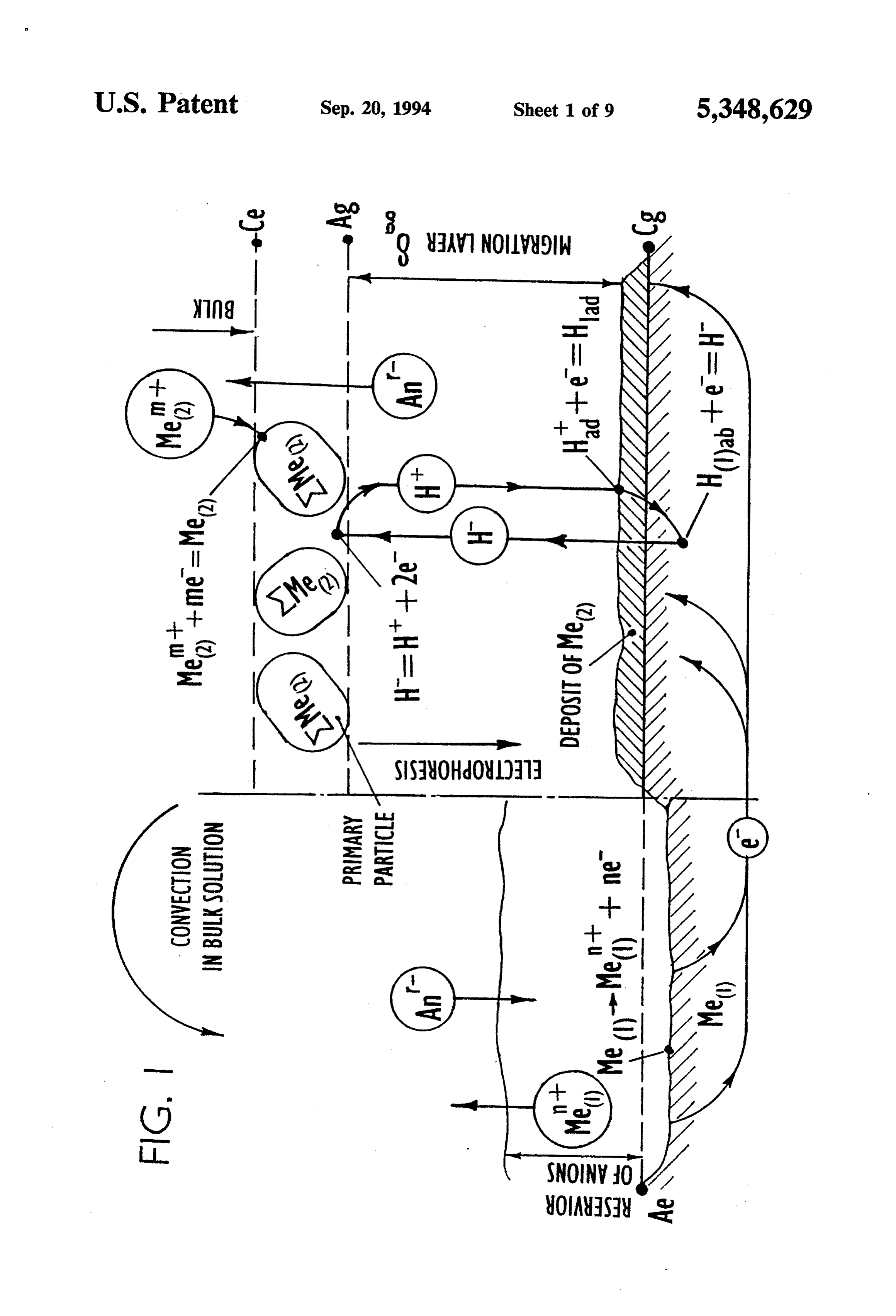
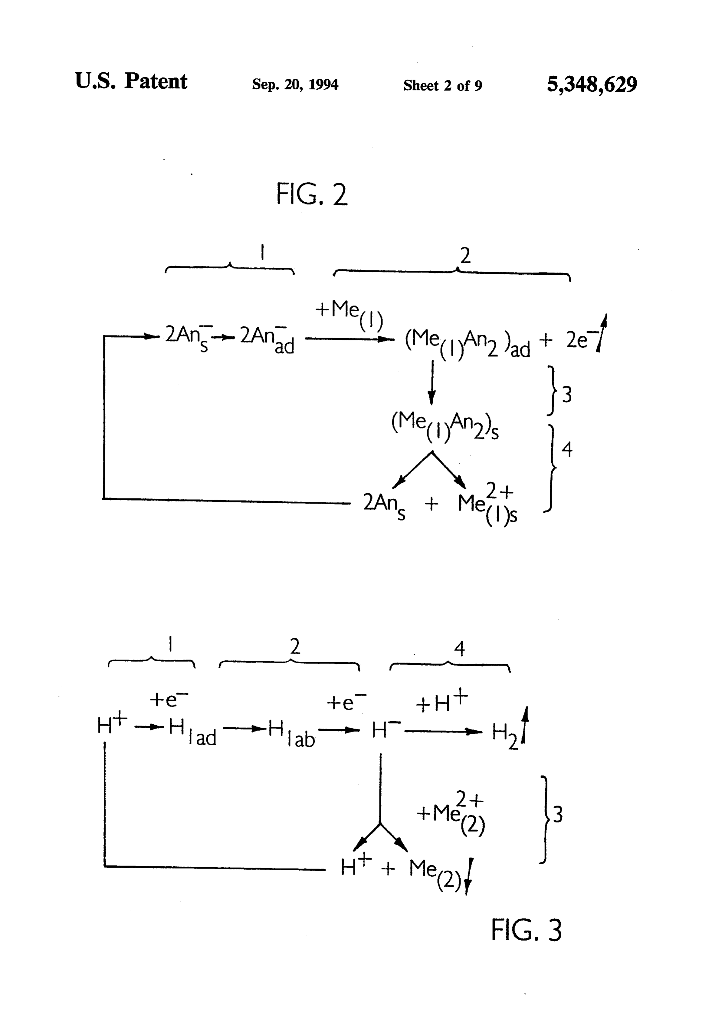
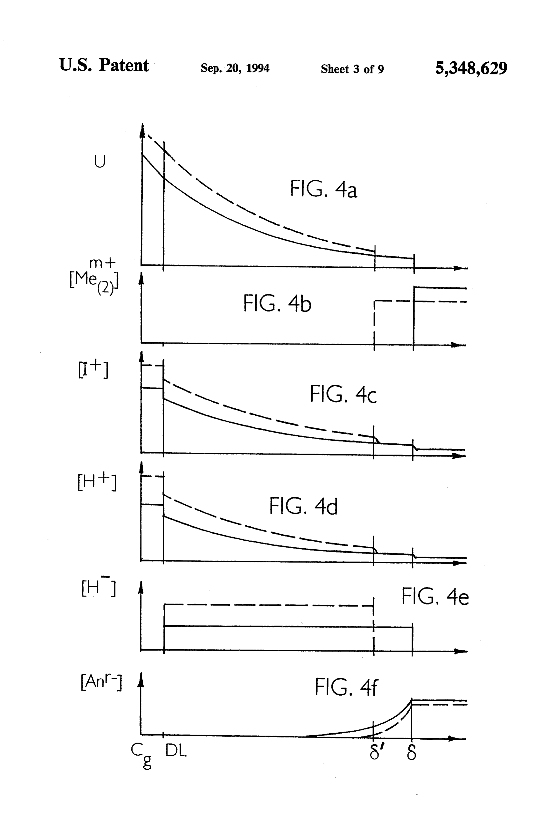
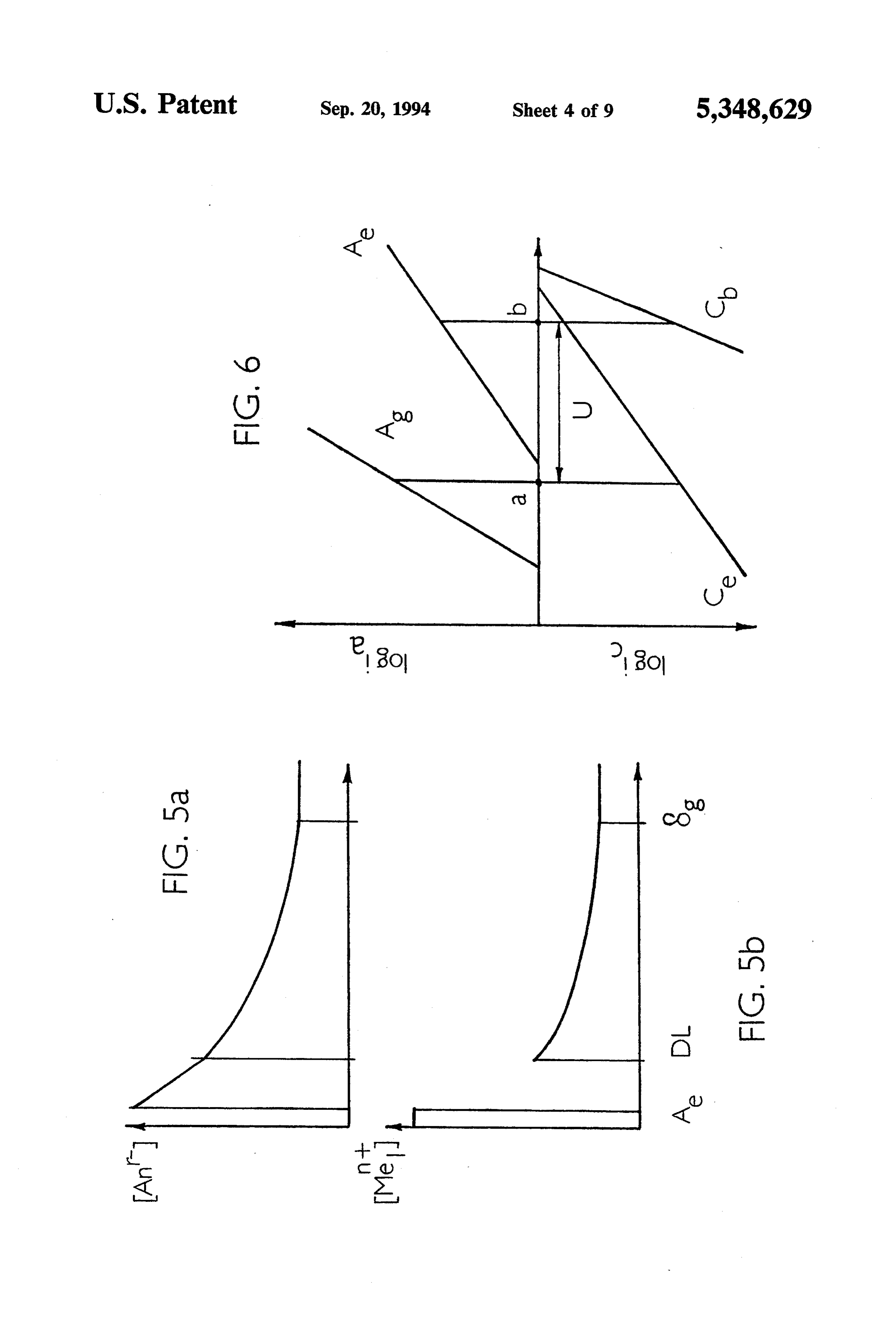
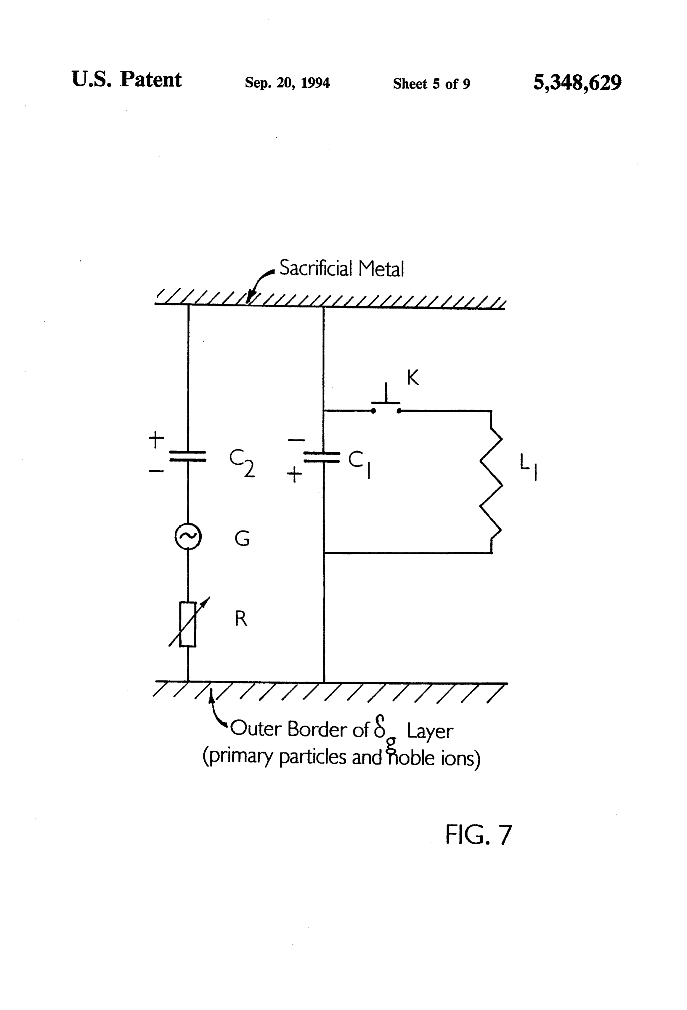
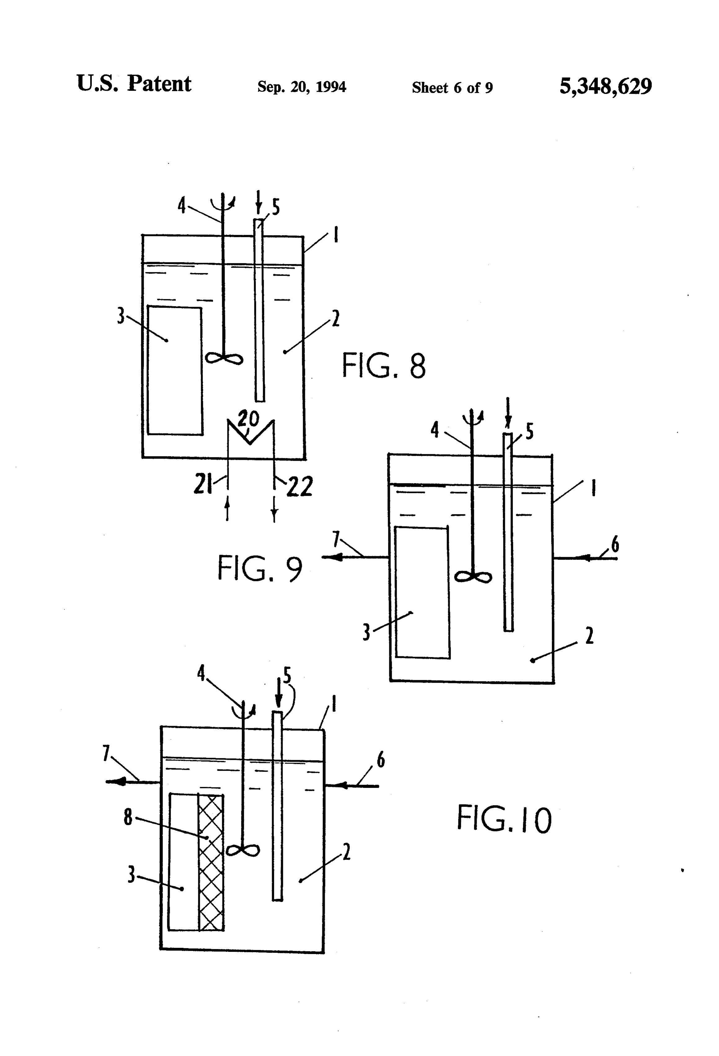
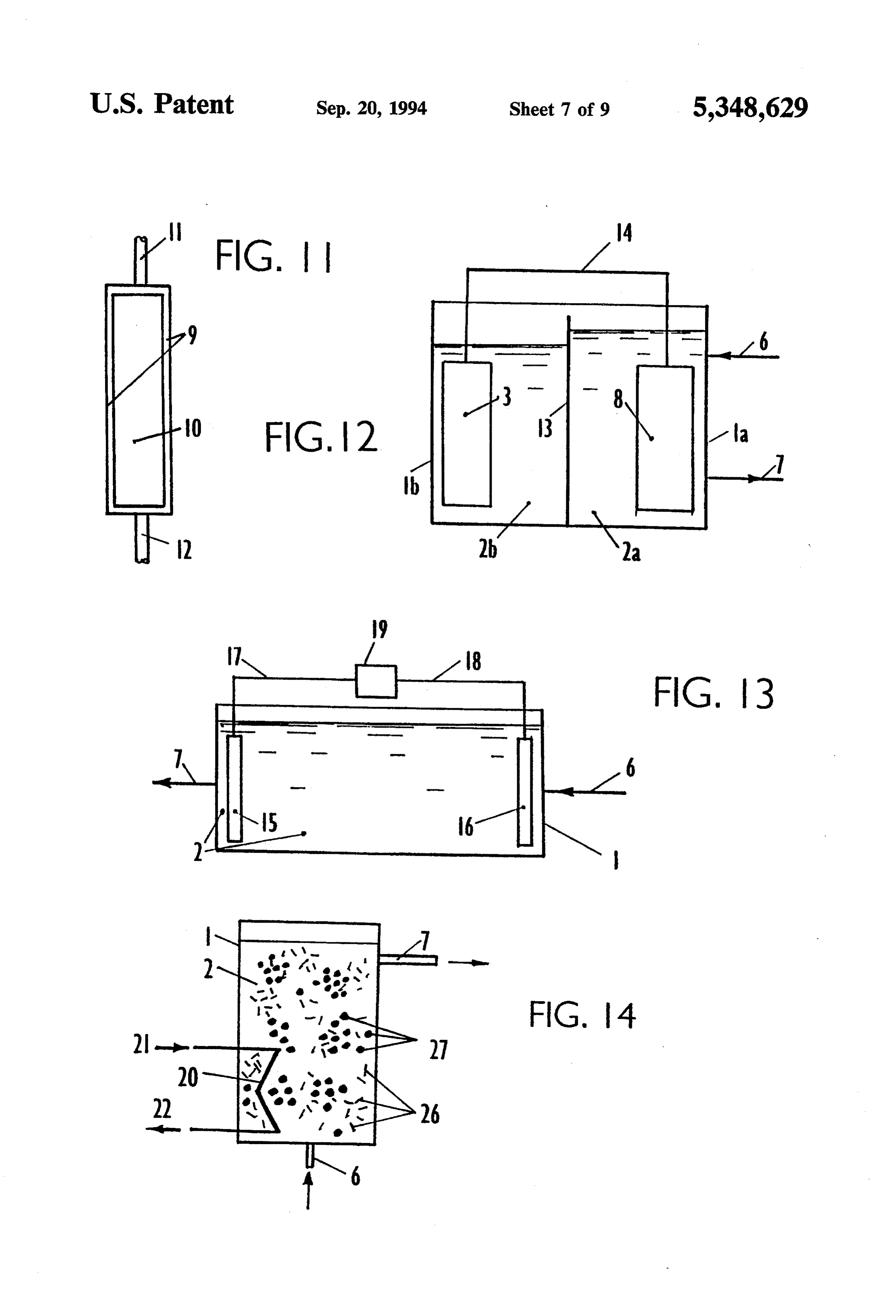
FIG. 1 is an illustration of the migrational mechanism to, Cl-, NH3, CN, and EDTA. “Noble metal species' of cementation processes; or "noble species”, “noble metal particles' or "noble FIG. 2 is an illustration of the electrode processes and 10 particles', and "noble species”, “noble metal particles,” transformations occurring at anodic sites in cementation or "noble particles', and "noble metal ions' or "noble systems; ions' refer to metal species, particles and ions, respec FIG. 3 is an illustration for the electrode processes tively, that are electropositive relative to another metal, and transformations occurring at the cathodic sites in usually referred to as the “sacrificial' or electronega cementation systems operated in migrational regimes; 15 tive metal. Examples of noble species can include, but FIG. 4 is a graphic representation of the potentials are not limited to, Cu2+, Agh, Hg, Cd2+, Cr2O72. and distributions of major ionic species in the galvanic The term "cementation electrolyte' refers to an electro cell; lyte that contains at least one noble species. The term FIG. 5 is a graphic representation of distributions of "filament' is meant to refer to a protrusion of any shape anions and cations at the anodic sites; that ends in a relatively sharp point. The term "electro FIG. 6 is a current-potential diagram of the cementa chemical processing of materials' is meant to refer to tion system; any and all chemical, physical or chemical physical con FIG. 7 is an equivalent electric circuit of cementation versions, transformations and separations effected by processes; electromagnetic and/or electrokinetic forces. FIG. 8 is a cross-section of a batch reactor for cemen 25 1. The Migrational Transport Layer and Related Elec tation induced processing of materials; trode Processes
FIG. 9 is a cross-section of a flow through reactor for As described in Boris Mikhail Khudenko, "Mathe cementation induced processing of materials; matical Models of Cementation Processes', Proc. Eny. FIG. 10 is a cross-section of a cementation reactor for Eng. Div., Amer. Soc. Civil Eng., 113:681-701 (1987), two processing of materials with a composite electrode 30 possible mechanisms for transferring species across the made of interconnected sacrificial metal and a noble boundary layer at cathodic sites are possible: diffusional cathodic metal; and migrational. When the species participating in elec FIG. 11 is a cross-section of a flow through noble trochemical processes are transported by diffusion, all metallic cathode for pulsing noble metal salts in the cathodic reactions occur at the surface of the cathodic course of reinduction of migrational regimes; 35 sites, or, in accordance with conventional models, FIG. 12 is a cross-section of a reactor for cementation within the adsorption layer at this surface. induced processing of materials with separate cementa A schematic showing the electrochemical reactions tion and processing zones. occurring during the migrational transport of species is FIG. 13 is a cross-section of a reactor for processing illustrated in FIG. 1. Because the properties of metal of materials driven by an external source of electricity; surfaces are nonuniform, multiple electrolytic (cathode FIG. 14 is an illustration of a fluidized bed reactor for Ce and anode A) and galvanic (anode Ag and cathode the cementation induced processing of materials; C) cells are spontaneously induced. A cell is termed FIG. 15 is a cross-section of a membrane reactor for "electrolytic' based upon the original cementation pro the electrochemically driven processing of materials; cess objective of reducing noble species through elec FIG. 16 is a cross-section of an alternative embodi 45 trolysis. Cells that do not reduce noble species through ment of a membrane reactor for the electrochemically electrolysis are referred to as galvanic cells. Electro driven processing of materials. lytic cells include anodic sites Ae, a boundary layer Be FIG. 17 is a chromatogram of wastewater from a at anodic sites Ae, the bulk solution, and cathodes Ce, wood preservation plant after treatment by coagulation. located opposite the cathodic sites Cg on the sacrificial FIG. 18 is a chromatogram of wastewater from a 50 metal surface. Galvanic cells are comprised of cathodic wood preservation plant after treatment in the cementa sites Cg a migration layer 8, and anodes Agadjacent to tion induced process. cathodes Ce. Anodes Ag and cathodes Ce are associated DETAILED DESCRIPTION OF THE with primary particles marked in FIG. 1 by the symbol INVENTION XMe(2). Me(1) refers to sacrificial metal species and 55 Me(2) refers to noble metal species.
This invention relates to a method and apparatus for Typically, the bulk solution contains noble ions, ei processing of materials in a migrational transport layer ther cations Meoymt, such as Cu2+, Agt, noble metal formed off the surface of a metal in an electrochemical containing anions, such as Cr2O72", or other electron system. The following subsections describe the forma accepting species; acids, such as H2SO4 or HCl, or alka tion mechanism, statics, and dynamics of a migrational lies for pH control; and indifferent ions I, An, transport layer in an electrochemical system; the mech which do not participate in electrode reactions. Com anisms usable for processing materials that occur in plexing agents, for example cyanides, may also be used. such a layer; the variables that control the layer; and Electrode processes and transformations occurring at preferred embodiments utilizing the layer. the anodic sites Ae of FIG. 1 in electrolytic cells are As used herein, the term "promoter” refers to nega 65 illustrated in FIG. 2, using univalent anions and a diva tively charged ions or neutral species capable of being lent sacrificial metal as an example. These processes and reduced at the cathode. Examples of promoters include, transformations involve the following: (1) adsorption of but are not limited to, Cr2O72- and VO43-. The term anions An, from the bulk solution on the surface of
Page 13
sacrificial metal Me(1); (2) formation of a salt and libera E= -1.125-1-RT/2F in H/H). Because the same tion of electrons that flow to cathodes C in galvanic species, hydrogen and hydride ions, constitute both cells; (3) dissolution and (4) dissociation of salt mole cathode Cand anode Ag the galvanic cell is a concen cules. Dissolved metal cations remain in the bulk solu tration element. Additionally, hydrogen ions disappear tion while the anions may return to the anodes Ag at C, while hydride ions completely disappear because Transformations at the cathodic sites, electrodes C. of fast electrode reactions at Ag.
Ag, and Ce of FIG. 1, involve the following steps as 2. Statics of the Migrational Transport Layer shown in FIG. 3: (1) acceptance of an electron by hy Although the cementation process is essentially dy drogen ion and the consequential formation of adsorbed namic, a discussion of the statics of the process is neces atomic hydrogen Had, (2) diffusion of the atomic hydro 10 sary to establish a framework to describe the process gen into the body of the sacrificial metal to produce dynamics. First, Ohm's law can be applied to the elec Hab, the resulting association with electroconducting tric current within the 8g layer, giving rise to a potential electrons to form hydride ion, H, and the ejection of a gradient. Under the influence of this potential gradient, negative particle (a hydride ion) from cathodes Cg as cationic species that approach the electrode Agby con shown in FIG. 1; (3) transportation of hydride ions in 15 vection in the bulk solution will be pumped into the the boundary layer and reaction with noble species, migration layer (6), whereas anionic species will be which results in the formation of reduced products and pumped out of this layer (with the exception of noble in the recovery of hydrogen ions; and (4) a side reaction and hydrogen species which disappear at the Ag elec between hydride and hydrogen ions to form molecular trode).
hydrogen. The H+ and H- species constitute specific 20 Under this pumping effect, an accumulation of hy hydrogen electrodes (H+ +2e.--H- and drogen, H+, and indifferent cations such as Naoccurs H-H +2e) which differ from the standard hydro in the layer ög. Accordingly, a considerable concentra gen electrode (2H +2e-H2). Hydride ions may be tion gradient and diffusional backflow of these ions transported in accordance with a relay mechanism in takes place, and, therefore, the velocity of hydrogen which weakly bound electrons jump from one proton to 25 ions in the electrical field decreases. In contrast, hy another. A similar relay mechanism has been described dride (or relayed electrons) will be pumped out of the for the transport of hydronium ions H3O+ in electric 6g layer under the influence of both the electrical forces fields. Depending on the transportation mode, the trans and diffusional phenomena. A graphic presentation of formations at the cathodic sites shown in FIGS. 1 and 3 relative potentials and distributions of ionic species in may be spatially separated, or may occur at the sacrifi 30 the galvanic cell for a static case is given in FIG. 4. cial metal surface. Solid lines in FIG. 4 are related to a single noble specie, At the initiation or spontaneous induction of cemen while broken lines illustrate the effects of multiple (two) tation, an electrical double layer is formed at cathodic noble species; 6 and 6' refer to the distance of the reac sites. The outer Helmholtz layer is comprised of hydro tion front edge of the migrational layer ög from cath gen ions, noble cations, and indifferent ions such as 35 odes Cg when a single noble specie and multiple noble Na. As a result of the interaction between hydrogen species are present, respectively. DL refers to the elec ions and electrons, hydride ions are emitted from ca trical double layer present at the electrodes. thodic sites, while noble ions diffuse from the bulk solu Indifferent cations I+ do not take part in the elec tion towards the cathodic sites. Thus, two opposite trode reactions in the galvanic cell. Accordingly, they fluxes are formed: a hydride flux and a counterflux of 40 accumulate within the galvanic cell and are distributed noble ions. The species in these fluxes react with each across the cell as shown in FIG. 4c; these ions migrate other (H---Me2+-H+ --Me). towards the electrode C under the force of the electric At the onset of the cementation process, either the field and flow back because of diffusional effects. These hydride flux or the noble cation flux is greater. In the phenomena, and the resulting distribution of ions, are former case, the reaction between ions in these fluxes 45 analogous to the sedimentation-diffusion equilibrium for results in the disappearance of noble ions from the layer colloidal particles in liquids. A small quantity of indif. adjacent to the cathodic sites and the reaction front ferentions diffuses out from the 8 layer. The resultant moves to a distance 8 from the cathodic sites where gradual drop in concentration of indifferent ions at the these fluxes are equal (see FIGS. 1 and 4b). In this case, outer border of the 8 layer is also shown in FIG. 4c. electrodes Ag and Ce would form at the reaction front. 50 The distribution of hydrogen ions (FIG. 4d) is similar The initial potential determining processes at these elec to that of indifferent ions. However, because H3Ot trodes and at the cathodic sites Care shown in FIG. 1. possesses an exceptionally high electric mobility and, The hydrogen ions recovered at the electrode Agcreate thus, a higher ratio of electric to diffusional forces, the a flow across the 8g layer and counterfluxes of H+ and distribution of hydrogen pumped into the 8g layer is H ions in this layer create an electrical current, thus 55 characterized by a steeper curve, reflecting a greater constituting the migrational transport of species at ca proportion of hydrogen ions as compared to indifferent thodic sites. ions in the vicinity of electrodes C. As with indifferent In the latter case, in which the diffusion flux of nobleions, hydrogen ions leak out of the Ög layer because of species is greater than the flux of hydride, the reaction diffusion. In contrast to indifferent ions, however, hy front is shifted towards the cathodic sites. Transitional drogen ions react at the electrode C to form hydride regimes between these two situations are theoretically 1O.S.
possible when initial hydride and noble ions fluxes are Hydride ions (or electrons originating from hydride nearly equal; however, such regimes are not likely to be ions) are ejected from the electrode C and are further stable. repulsed from the Ög layer under electrostatic forces as The main reactions at electrodes Cg and Ag are 65 shown in FIG. 4e. Anions (FIG. 4f) are also pumped out H+ +2e.--H- and H-->H+ +2e, respectively. The of the 8g layer.
equilibrium potentials (volts) that are thermodynami When two or more different noble ions are used, a cally possible at these electrodes are given by synergistic effect on the process rate may occur. Such
Page 14
an effect can be attributed to the following three fac potential-current diagram for the migrational cementa tors: different reduction potentials, different diffusivity, tion regime. The diagram is a plot of log i versus E, in and different ion charge (either plus or minus). These which ia and ic are anodic and cathodic currents, respec three factors effect the individual thickness of the Ög tively, and E is the potential. Evaluation of the magni layer for a given noble specie. An analogous phenome 5 tude of the potential difference, U=a-b, across the 8g non was described by Levich in Physicochemical Hydro layer and across the bulk solution and the boundary dynamics, Prentice Hall, 1962, in relation to diffusion in layer at anodic sites will be given later. The value of U various mass transfer processes. FIG. 4 illustrates the reflects the magnitude of the tension produced through distributions of potentials and concentrations of react the push-pull effect.
ing and indifferent species for two noble species (broken Anodic and cathodic sites arise because of defects in and solid lines). The width of the migration layers for the lattice structure on the surface of sacrificial metal. these species are 8'gand 6 respectively. It follows from When a single pair of anodic-cathodic sites occurs, it FIG. 4 that the potentials and concentrations at point 8' induces multiple sites on the entire surface of the sacrifi change stepwise and the average potential gradient cial metal exposed to the electrolyte. Moreover, the becomes steeper when two noble species are reduced as 15 electrical fields in all pairs of cells are basically identi compared to a single specie. Accordingly, both species cal. For example, a sacrificial metal may be a clump of may be reduced faster than either of them taken individ twisted wire. The electrical cells inside and outside the ually. A combination of noble species can be used to clump will have similar characteristics. However, the induce, accelerate, or reinduce the migrational cemen fields developed at sharp edges will be stronger. tation regime. Some noble species, particularly nega 20 Electrical cells will also be induced across a mem tively charged ions such as Cr2O72 or reducible elec brane having a cementation electrolyte on one side and trically neutral species, may be used as promoters of the an electrolyte lacking noble species on the other side. migrational cementation regime. Processes other than the reduction of a noble species Considering the effect of cations being pumped into may be performed on the "opposite' side of the mem and anions pumped out of the 8g layer, the electrolyte 25 brane. Sacrificial metal can be attached to a more noble within the galvanic cell is positively charged. However, metal, which becomes polarized cathodically. Thus, the bulk solution remains electroneutral. For the overall galvanic cells are induced on the surface of the more system to remain electroneutral, therefore, a quantity of noble metal.
anions equivalent to the excess hydrogen and indifferent The positive charge within the 8 layer caused by cations accumulated in the galvanic cell must accumu 30 hydrogen ions is not conserved because hydrogen ions late at anodic sites Ae. These accumulated anions take part in electrode reactions and disappear from this "push' and the hydrogen and indifferent cations "pull' layer. For example, H reacts to form molecular hydro the electrons in the sacrificial metal, giving rise to the gen when noble ions become depleted. Accordingly, so-called push-pull mechanism. the relaxation of the positive charges, and thus the nega Anions are electrostatically attracted to the anodic 35 tive charges, would occur rapidly. However, this relax sites Ae and diffuse in the opposite direction. Cations at ation can be slowed when indifferentions are present in anodic sites, including those that originated from the the electrolyte because they constitute a fraction of the dissolution of the sacrificial metal, are repulsed from the positive charge in the 8 layer. Moreover, when hydro anodic sites under the action of electrostatic forces. The gen ions disappear from the 8g layer, they are substi distributions of anions and cations at anodic sites are tuted by indifferent ions. Thus, two properties of indif. illustrated in FIGS. 5a and 5b. ferent ions are important: electrical mobility and dif Once established, the reservoirs of positive and nega fusivitiy. An optimal relationship between mobility and tive charges at the cathodic and anodic sites, respec diffusivity can be achieved by using a mixture of various tively, will not change substantially during the course of indifferent ions such as Li,Na+, K+, etc. the process because of a mutual attraction through the 45 3. Dynamics of the Process body of a metal. Thus, a virtually constant push-pull The migrational layer ög and the layer at anodic sites tension and a virtually constant potential difference, can be analogized to capacitors. Considering that reduc averaged over long time intervals, is created. Slow tion of noble species and oxidation of sacrificial metal relaxation of these charge reservoirs may occur from result in the production of electrical energy, the electro the diffusional leakage of anions and cations from 50 chemical system comprised of anodes Ae, cathodes Ce boundary layers at anodes and cathodes, respectively. , and the associated electrolyte can be considered as a For example, such leakage may occur when the jump in generator of electricity. It is also suggested herein that the electric potential at the outer border of the 8g layer the electric current across the 6 layer occurs in re decreases upon the depletion of noble species in a batch peated pulses, each pulse similar to a break down cur process. 55 rent in a capacitor. This current is triggered by the The electric current in the system flows from the accumulation of electric charges in the capacitor and electrode Ae to the electrode C (flow of electrons), the subsequent deformation in the distribution of cations from C to Ag (flow of hydride ions, or electrons, and in the 6 layer. During flow of the break down current, electrical-diffusional motion of hydrogen and indiffer the Ög layer can be considered as an inductance. After entions), from Ag to Ce (electrons), and from Ceto Ae each pulse, the distribution of cations within the 8 layer (current in a binary electrolyte in the bulk solution, becomes more uniform and the layer becomes a capaci electrical-diffusional flow of anions, and predominantly tor again. The overall system also has some active resis electrical flow of sacrificial cations in the boundary tanceS.
layer at anodic sites). Electrodes Ae and C as well as FIG. 7 shows an equivalent electrical circuit which Ag and Ce, are short-circuited by the sacrificial metal 65 reflects a number of major processes in the overall sys and the primary particles respectively. Accordingly, tem. In FIG.7, capacitor C1 corresponds to the 8 layer, these pairs of electrodes have the same potentials a and L1 is the inductance, K is a trigger, R is an active resis b as shown in FIG. 6, which illustrates an instantaneous tance, G is a generator and C2 is a capacitor at the anode
Page 15
Ae. The sacrificial metal and the outer border of the 8 After capacitor C1 is discharged, the current through layer are electric conductors. inductance L1 is interrupted, which corresponds to The plates of the capacitor C1 are formed by cathodes trigger K being turned off. The capacitor C1 then be C and the outer border of the 8g layer containing pri comes charged from capacitor C2 and the cycle is re mary particles and noble species. Aqueous indifferent peated.
cations and hydrogen ions constitute a specific dielec This electric circuit is a typical resonant circuit, tric between plates. The polarization of such a dielectric which produces resonances in the electric tension and is determined by the balance of electrostatic and diffu currents. Considering that the losses caused by the ac sional forces acting upon these cations. The electro tive resistance are completely compensated by the en static forces provide order, while diffusional forces 0. ergy generated in the electrochemical processes and the produce disorder in the dielectric. Taken over a short frequency of the energy generator G completely coin period of time (the duration of the charging period), cides with the natural frequency of the resonant circuit, mobile cations prevent the break down of the capacitor amplification of the electric tension and the electric C1 and, thus, substantial charges and a voltage differen currents must be very large.
tial arise in the capacitor C1. 5 Referring to FIG. 6, the value of potential difference The capacitor becomes charged by the above U can be considered as the potential difference induced described pumping and push-pull mechanisms. When in the resonant circuit. Considering the process dynam the potential difference between the capacitor's plates ics, the phases of U for capacitors C2 and C1 (or induc reaches the break down voltage, electric current flows tance Li) are opposite, while the phase of the electric between the plates. The break down current occurs in 20 current and the tension for inductance L1 (capacitor C1) the form of short-lived streamers, forming a tunnel of are slightly shifted. The discharge in the galvanic cell positively charged particles that are present in the 8g becomes a high-voltage, high-current pulsed discharge layer because of the pumping and push-pull effects (in and, therefore, a high power discharge. The magnitude different and hydrogen cations) with negative particles 25 of the voltage difference U can be estimated as shown (electrons that originated from hydride ions) forming below: The width of the 6 layer can be estimated using the core of the streamer. Because streamers are short Levich's formula lived, the break down current changes very rapidly.
Accordingly, this current induces very strong electro magnetic fields and the streamers can be considered as 30 where u is the water viscosity, Da is the coefficient of inductance Ll in the overall electric circuit.
Streamer formation is facilitated by the non-uniform diffusion tive to of ions in water, v is the water velocity rela electrodes, x is the distance along the speed ity of the electric field in the 6 layer (capacitor C).
This non-uniformity, in turn, can be attributed to rough vector (xat1mm). Taking the values of v = 102 cm2/s, deposits of noble metal on the surface of cathodic sites 35 D=10-5 cm2/s, v= 102 cm/s, and x=10-1 cm, the value of 8g=3.10-cm. Considering that the surface.
Cand discontinuities in the outer border of the 8 layer layer of the cathodes is saturated with hydride ions, or where discrete minute primary particles and noble ions the density of hydride is about 1023ions/cm3, and taking are located. The electric field is strongest between de the thickness of the saturated layer of 102cm, the den posit protrusions and the discrete points in the outer border of the Ög layer. Accordingly, cations migrate sity of the electric charge at the cathode is Q=0.8-10-2 towards a line connecting these protrusions and discrete C/m2. The intensity of the electric field is defined as points, forming the streamer's shell and attracting elec trons into the core of the streamer. Once a streamer is formed (corresponding to closing the trigger Kin FIG. where e is the dielectric permittivity of water (e=80) 7), a rapidly changing pulsed current occurs. This cur 45 and eo is the free space permittivity. Accordingly, rent produces a strong electromagnetic field, which E=105 V/sm. For the value of 8=3.10-cm, the volt causes the cross-section (diameter) of the streamer to age difference across the 8 layer is 30 V. contract and, thus, the streamer's body becomes mo Referring to FIGS. 4, 5, and 6, the distribution of mentarily separated from the surrounding water. Ac species and potentials, as well as the electrode currents, cordingly, the plasma in the streamer is in a vacuum 50 should be taken as instantaneous pictures of a dynamic and, therefore, no energy is lost to the surrounding process. All these values change very rapidly. More media on the sidewall (shell) of the streamer.
In the electric field in the specific dielectric within slightly shifted asofdescribed over, the phases these changes are either opposite or above.
the 8g layer, electrons and cations are accelerated; elec Thus, in accordance with the description presented trons move towards the outer border of the 8 layer, 55 herein, the essential element of the method includes the while cations move towards cathodes C. A relay mo induction of the migrational layer 8, within which H+ tion of electrons surrounded by cations of hydrogen in and H ions and electrons originating from H are streamers occurs from cation to cation and the overall accelerated in a very strong local electrical field. As electron motion can be considered as equivalent to the previously described, such a layer can be induced in transport of hydride ions originally formed at cathodes cementation systems. Induction of such a layer can be C. Electrons react with noble species at the outer bor further promoted by the use of promoters, such as nega der of the 8g layer. tively charged reducible noble ions (for example, When trigger K is on (break down of capacitor C1) and rapidly varying electric current is flowing through Cr2O72-). The essential reasons for the induction of migrational layer are (1) the availability of electron inductance L1, a strong electromagnetic field is in 65 acceptors at the outer bondary, and (2) a very high duced, resulting in a current that charges the capacitor current density over the cathodic area. C2. Physically, this corresponds to pushing electrons In addition, the cathodic area can be increased by from and attracting anions to the anodic sites Ae. using a cathode composed of a metal more noble than
Page 16
the sacrificial metal such that these two metals are con noble salt solution having an optimal concentration of nected and attached to each other and submerged in a noble metals.
solution of a noble metal salt. A further modification Alternatively, the process rate may be increased by includes electrically connecting the sacrificial and noble employing fluidized electrodes made of sacrificial metal metals and submerging them in separate vessels; the 5 particles, chemically neutral particles such as gold or sacrificial metal is submerged in a solution in which it platinum, or particles of the same metal as the noble becomes anodically dissolved (for example, an acid), cations, for example, copper, silver, etc. In the latter while the more noble cathodic metal is submerged in a case, particles formed in cementation processes (cement solution of a salt of a noble metal. Metals included in powders) are preferred. Chemically neutral particles this salt should not necessarily be the same metal as the 10 and particles of the same metal as the noble cations can cathodic metal. For example, the sacrificial metal can be be added to either a cementation system or to an electri zinc, the noble cathodic metal may be platinum, and the cally driven system.
noble metal of a dissolved salt may be copper. Other A combination of a cementation and electrically combinations of metals are also possible. driven process can also be possible in which the migra Also, a cathodic noble metal can form a membrane 15 tional layer is induced by a cementation mechanism that separates the vessel (or compartment) for dis followed by cathodic polarization of the sacrificial solving the sacrificial metal from the vessel (or com metal, thus making the sacrificial metal behave as a partment) for the cementation of the noble metal con more noble metal. In this process, consumption of sacri tained in the dissolved salt onto the cathodic noble ficial metal would be reduced. Additionally, the optimal metal. Moreover, the membrane may also be made of 2O concentration of the noble metal species can be pro vided only during the induction period, reducing the the sacrificial metal. If so, however, the sacrificial metal consumption membrane would eventually dissolve. When heavy of noble metal salts. water is used in the vessel (or the compartment) con fectA of reducing atmosphere eliminates the retarding ef. taining the solution of the noble metal salt, the nuclear 25 oxidizesoxygen hydrogen at the cathodic sites, in which oxygen ions and reduces the effective flux of reactions listed above would also take place. hydrogen species. A reducing atmosphere can be pro Alternatively, the migrational layer ög, with all prop vided by bubbling H2 gas into the electrolyte. The use erties as described above for cementation systems, can be induced by applying high current densities in electro of a neutral atmosphere, such as N2 gas, also reduces the lytic baths operated at moderate mixing levels and low 30 negative effect of oxygen. The sacrificial metal or electrodes can be formed to moderate concentrations of noble metals (or metals from Zn, Mg, Ca, Al, Fe, Ni, Co, and other inexpensive being plated). For example, in electrolytic baths for or moderately expensive metals or alloys. plating (or refining) various metals, powdery metals are 4. Control Variables sometimes formed. The regimes at which powdery metals are formed correspond to the induction of the 35 be controlled by an rate
The cementation in the migrational regime can appropriate selection of noble spe migrational layer at localized cathode areas. The induc cies, singly or in mixtures; optimal concentrations of tion of such localized areas is encouraged by the use of noble species, singly or in mixtures; optimal pH; optimal rough cathodes. Accordingly, the use of cathodes selection of indifferent ions, singly or in mixtures; opti formed from mesh and various ridge, valley, and other mal concentrations of indifferent ions, singly or in mix shapes having protrusions promotes the induction of 40 tures; optimal selection of anions, singly or in mixtures; localized migrational zones at the cathode surface. optimal concentrations of anions, singly or in mixtures; A process in a reactor with electrodes to which a optimal selection and concentrations of complexing pulsed current is applied from an external source can be agents; optimal mixing rate; a reducing atmosphere; and used. In this process, the pulsed current induces the an optimal temperature. The effects associated with migrational layer and, thus, emulates the cementation 45 these factors are discussed above and in Khudenko, process. Pulsed current should provide a very high “Mathematical Models of Cementation Processes,' cathodic current density as required for the migrational Proc. Env, Eng. Diy, Amer. Soc. Civil Eng., 113:681-701 regime. (1987); Gould et al., “Examination of the Zinc Cemen The effectiveness and the rate of cementation pro tation of Cadmium in Aqueous Solutions,” Water Sci cesses in migrational regimes, whether induced by ce 50 ence and Tech., Vol. 19, Rio (1987); and Khudenko et mentation or by applying high current densities, depend upon the magnitude and the density of hydride-hydro al., “Specifics of Cementation Processes for Metals Removal,” Proc. of the 5th Int. Conf on Advanced Waste gen fluxes in the 8g layer; greater hydride-hydrogen water Treatment and Reclamational IAWPRC, Vol. 2, fluxes result in greater cementation rates. As described Cracow, Poland, (1989). As discussed above, external previously, hydrogen and hydride ion fluxes are in 55 sources of electricity, or their combination with cemen duced to match (to equal approximately) the original tation processes, can be used to control the process. diffusional flux of noble species that occurs at the time 5. Preferred Embodiments the migrational layer is induced. An optimal concentra The following embodiments illustrate various aspects tion of noble species can be used at the induction period of the invention, but are in no way intended to limit the only to produce the maximal hydrogen-hydride fluxes. scope thereof. Like reference numbers refer to like parts Thereafter, a lower, or greater, concentration of noble in the various Figures.
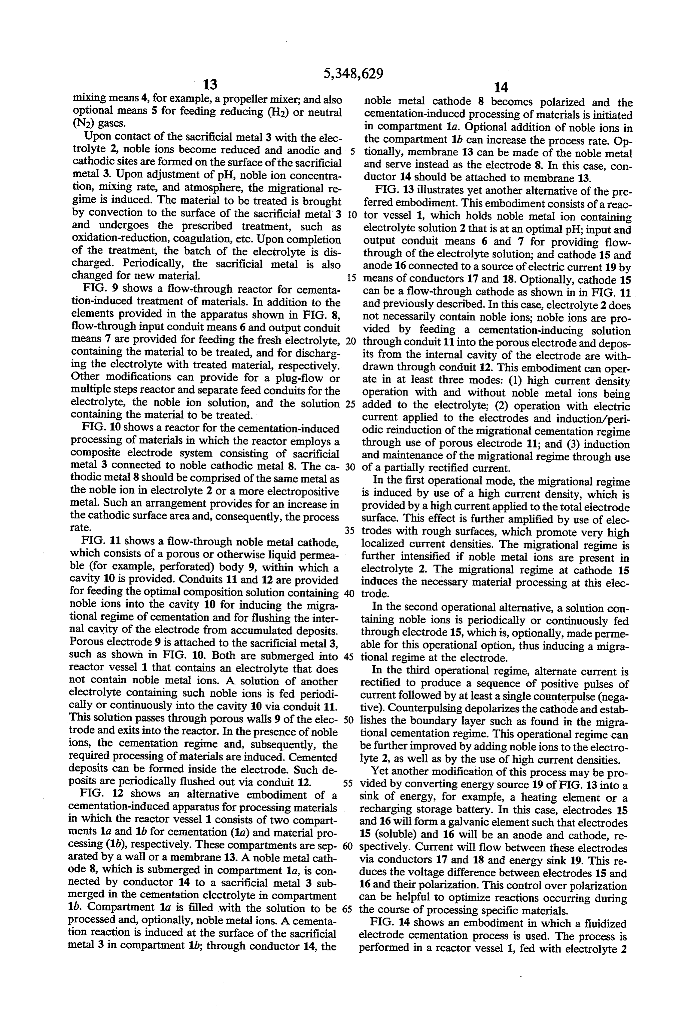
ions would not change the fluxes and the maximum FIG. 8 shows a batch reactor for cementation process rate could be maintained for a substantial period induced processing of materials. The reactor consists of of time. Periodically, reinduction of optimum fluxes a vessel 1 that is periodically filled with electrolyte 2, may be needed because of relaxation processes. Such 65 which contains the material to be treated, noble ions, reinduction can be performed by using hollow, perfo optionally acid or alkali for optimum pH, and also, rated, or porous electrodes (such as those made by the optionally, promoters of the migrational regime; a sacri use of metal powderfusing) with periodic injection of a ficial metal 3 submerged in electrolyte 2; an optional
Page 17
mixing means 4, for example, a propeller mixer; and also noble metal cathode 8 becomes polarized and the optional means 5 for feeding reducing (H2) or neutral cementation-induced processing of materials is initiated (N2) gases. in compartment 1a. Optional addition of noble ions in Upon contact of the sacrificial metal 3 with the elec the compartment 1b can increase the process rate. Op trolyte 2, noble ions become reduced and anodic and tionally, membrane 13 can be made of the noble metal cathodic sites are formed on the surface of the sacrificial and serve instead as the electrode 8. In this case, con metal 3. Upon adjustment of pH, noble ion concentra ductor 14 should be attached to membrane 13. tion, mixing rate, and atmosphere, the migrational re FIG. 13 illustrates yet another alternative of the pre gime is induced. The material to be treated is brought ferred embodiment. This embodiment consists of a reac by convection to the surface of the sacrificial metal 3 10 tor vessel 1, which holds noble metal ion containing and undergoes the prescribed treatment, such as electrolyte solution 2 that is at an optimal pH; input and oxidation-reduction, coagulation, etc. Upon completion output conduit means 6 and 7 for providing flow of the treatment, the batch of the electrolyte is dis through of the electrolyte solution; and cathode 15 and charged. Periodically, the sacrificial metal is also anode 16 connected to a source of electric current 19 by changed for new material. 15 means of conductors 17 and 18. Optionally, cathode 15 FIG. 9 shows a flow-through reactor for cementa can be a flow-through cathode as shown in in FIG. 11 tion-induced treatment of materials. In addition to the and previously described. In this case, electrolyte 2 does elements provided in the apparatus shown in FIG. 8, not necessarily contain noble ions; noble ions are pro flow-through input conduit means 6 and output conduit vided by feeding a cementation-inducing solution means 7 are provided for feeding the fresh electrolyte, 20 through conduit 11 into the porous electrode and depos containing the material to be treated, and for discharg its from the internal cavity of the electrode are with ing the electrolyte with treated material, respectively. drawn through conduit 12. This embodiment can oper Other modifications can provide for a plug-flow or ate in at least three modes: (1) high current density multiple steps reactor and separate feed conduits for the operation with and without noble metal ions being electrolyte, the noble ion solution, and the solution 25 added to the electrolyte; (2) operation with electric containing the material to be treated. current applied to the electrodes and induction/peri FIG. 10 shows a reactor for the cementation-induced odic reinduction of the migrational cementation regime processing of materials in which the reactor employs a through use of porous electrode 11; and (3) induction composite electrode system consisting of sacrificial and maintenance of the migrational regime through use metal 3 connected to noble cathodic metal 8. The ca 30 of a partially rectified current.
thodic metal 8 should be comprised of the same metal as In the first operational mode, the migrational regime the noble ion in electrolyte 2 or a more electropositive is induced by use of a high current density, which is metal. Such an arrangement provides for an increase in provided by a high current applied to the total electrode the cathodic surface area and, consequently, the process surface. This effect is further amplified by use of elec rate. 35 trodes with rough surfaces, which promote very high FIG. 11 shows a flow-through noble metal cathode, localized current densities. The migrational regime is which consists of a porous or otherwise liquid permea further intensified if noble metal ions are present in ble (for example, perforated) body 9, within which a electrolyte 2. The migrational regime at cathode 15 cavity 10 is provided. Conduits 11 and 12 are provided induces the necessary material processing at this elec for feeding the optimal composition solution containing trode.
noble ions into the cavity 10 for inducing the migra In the second operational alternative, a solution con tional regime of cementation and for flushing the inter taining noble ions is periodically or continuously fed nal cavity of the electrode from accumulated deposits. through electrode 15, which is, optionally, made perme Porous electrode 9 is attached to the sacrificial metal 3, able for this operational option, thus inducing a migra such as shown in FIG. 10. Both are submerged into 45 tional regime at the electrode.
reactor vessel 1 that contains an electrolyte that does In the third operational regime, alternate current is not contain noble metal ions. A solution of another rectified to produce a sequence of positive pulses of electrolyte containing such noble ions is fed periodi current followed by at least a single counterpulse (nega cally or continuously into the cavity 10 via conduit 11. tive). Counterpulsing depolarizes the cathode and estab This solution passes through porous walls 9 of the elec 50 lishes the boundary layer such as found in the migra trode and exits into the reactor. In the presence of noble tional cementation regime. This operational regime can ions, the cementation regime and, subsequently, the be further improved by adding noble ions to the electro required processing of materials are induced. Cemented lyte 2, as well as by the use of high current densities. deposits can be formed inside the electrode. Such de Yet another modification of this process may be pro posits are periodically flushed out via conduit 12. 55 vided by converting energy source 19 of FIG. 13 into a FIG. 12 shows an alternative embodiment of a sink of energy, for example, a heating element or a cementation-induced apparatus for processing materials recharging storage battery. In this case, electrodes 15 in which the reactor vessel 1 consists of two compart and 16 will form a galvanic element such that electrodes ments 1a and 1b for cementation (1a) and material pro 15 (soluble) and 16 will be an anode and cathode, re cessing (1b), respectively. These compartments are sep spectively. Current will flow between these electrodes arated by a wall or a membrane 13. A noble metal cath via conductors 17 and 18 and energy sink 19. This re ode 8, which is submerged in compartment 1a, is con duces the voltage difference between electrodes 15 and nected by conductor 14 to a sacrificial metal 3 sub 16 and their polarization. This control over polarization merged in the cementation electrolyte in compartment can be helpful to optimize reactions occurring during 1b. Compartment 1a is filled with the solution to be 65 the course of processing specific materials. processed and, optionally, noble metal ions. A cementa FIG. 14 shows an embodiment in which a fluidized tion reaction is induced at the surface of the sacrificial electrode cementation process is used. The process is metal 3 in compartment 1b; through conductor 14, the performed in a reactor vessel 1, fed with electrolyte 2
Page 18
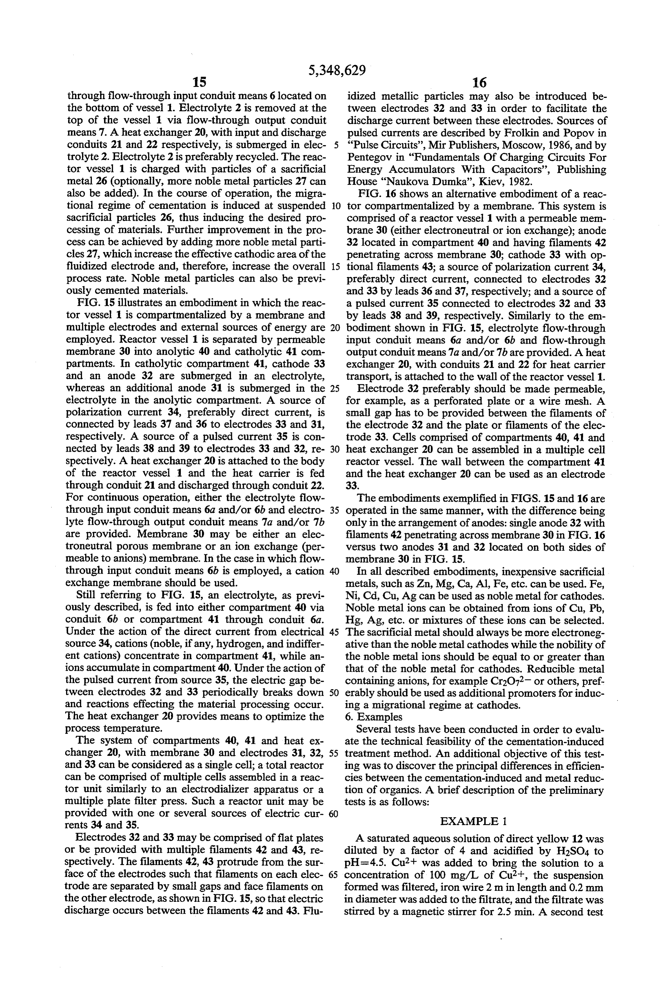
through flow-through input conduit means 6 located on idized metallic particles may also be introduced be the bottom of vessel 1. Electrolyte 2 is removed at the tween electrodes 32 and 33 in order to facilitate the top of the vessel 1 via flow-through output conduit discharge current between these electrodes. Sources of means 7. A heat exchanger 20, with input and discharge pulsed currents are described by Frolkin and Popov in conduits 21 and 22 respectively, is submerged in elec “Pulse Circuits', Mir Publishers, Moscow, 1986, and by trolyte 2. Electrolyte 2 is preferably recycled. The reac Pentegov in “Fundamentals Of Charging Circuits For tor vessel 1 is charged with particles of a sacrificial Energy Accumulators With Capacitors', Publishing metal 26 (optionally, more noble metal particles 27 can House "Naukova Dumka', Kiev, 1982. also be added). In the course of operation, the migra FIG. 16 shows an alternative embodiment of a reac tional regime of cementation is induced at suspended 10 tor compartmentalized by a membrane. This system is sacrificial particles 26, thus inducing the desired pro comprised of a reactor vessel 1 with a permeable mem cessing of materials. Further improvement in the pro brane 30 (either electroneutral or ion exchange); anode cess can be achieved by adding more noble metal parti 32 located in compartment 40 and having filaments 42 cles 27, which increase the effective cathodic area of the penetrating across membrane 30; cathode 33 with op fluidized electrode and, therefore, increase the overall 15 tional filaments 43; a source of polarization current 34, process rate. Noble metal particles can also be previ preferably direct current, connected to electrodes 32 ously cemented materials. and 33 by leads 36 and 37, respectively; and a source of FIG. 15 illustrates an embodiment in which the reac a pulsed current 35 connected to electrodes 32 and 33 tor vessel 1 is compartmentalized by a membrane and by leads 38 and 39, respectively. Similarly to the em multiple electrodes and external sources of energy are 20 bodiment shown in FIG. 15, electrolyte flow-through employed. Reactor vessel 1 is separated by permeable input conduit means 6a and/or 6b and flow-through membrane 30 into anolytic 40 and catholytic 41 com output conduit means 7a and/or 7b are provided. A heat partments. In catholytic compartment 41, cathode 33 exchanger 20, with conduits 21 and 22 for heat carrier and an anode 32 are submerged in an electrolyte, transport, is attached to the wall of the reactor vessel 1. whereas an additional anode 31 is submerged in the 25 Electrode 32 preferably should be made permeable, electrolyte in the anolytic compartment. A source of for example, as a perforated plate or a wire mesh. A polarization current 34, preferably direct current, is small gap has to be provided between the filaments of connected by leads 37 and 36 to electrodes 33 and 31, the electrode 32 and the plate or filaments of the elec respectively. A source of a pulsed current 35 is con trode 33. Cells comprised of compartments 40, 41 and nected by leads 38 and 39 to electrodes 33 and 32, re 30 heat exchanger 20 can be assembled in a multiple cell spectively. A heat exchanger 20 is attached to the body reactor vessel. The wall between the compartment 41 of the reactor vessel 1 and the heat carrier is fed and the heat exchanger 20 can be used as an electrode through conduit 21 and discharged through conduit 22. 33.
For continuous operation, either the electrolyte flow The embodiments exemplified in FIGS. 15 and 16 are through input conduit means 6a and/or 6b and electro 35 operated in the same manner, with the difference being lyte flow-through output conduit means 7a and/or 7b only in the arrangement of anodes: single anode 32 with are provided. Membrane 30 may be either an elec filaments 42 penetrating across membrane 30 in FIG. 16 troneutral porous membrane or an ion exchange (per versus two anodes 31 and 32 located on both sides of meable to anions) membrane. In the case in which flow membrane 30 in FIG. 15.
through input conduit means 6b is employed, a cation In all described embodiments, inexpensive sacrificial exchange membrane should be used. metals, such as Zn, Mg, Ca, Al, Fe, etc. can be used. Fe, Still referring to FIG. 15, an electrolyte, as previ Ni, Cd, Cu, Ag can be used as noble metal for cathodes. ously described, is fed into either compartment 40 via Noble metal ions can be obtained from ions of Cu, Pb, conduit 6b or compartment 41 through conduit 6a. Hg, Ag, etc. or mixtures of these ions can be selected. Under the action of the direct current from electrical 45 The sacrificial metal should always be more electroneg source 34, cations (noble, if any, hydrogen, and indiffer ative than the noble metal cathodes while the nobility of ent cations) concentrate in compartment 41, while an the noble metal ions should be equal to or greater than ions accumulate in compartment 40. Under the action of that of the noble metal for cathodes. Reducible metal the pulsed current from source 35, the electric gap be containing anions, for example Cr2O72 or others, pref tween electrodes 32 and 33 periodically breaks down 50 erably should be used as additional promoters for induc and reactions effecting the material processing occur. ing a migrational regime at cathodes. The heat exchanger 20 provides means to optimize the 6. Examples process temperature. Several tests have been conducted in order to evalu The system of compartments 40, 41 and heat ex ate the technical feasibility of the cementation-induced changer 20, with membrane 30 and electrodes 31, 32, 55 treatment method. An additional objective of this test and 33 can be considered as a single cell; a total reactor ing was to discover the principal differences in efficien can be comprised of multiple cells assembled in a reac cies between the cementation-induced and metal reduc tor unit similarly to an electrodializer apparatus or a tion of organics. A brief description of the preliminary multiple plate filter press. Such a reactor unit may be tests is as follows:
provided with one or several sources of electric cur 60 EXAMPLE 1. rents 34 and 35.
Electrodes 32 and 33 may be comprised of flat plates A saturated aqueous solution of direct yellow 12 was or be provided with multiple filaments 42 and 43, re diluted by a factor of 4 and acidified by H2SO4 to spectively. The filaments 42, 43 protrude from the sur pH=4.5. Cu2+ was added to bring the solution to a face of the electrodes such that filaments on each elec 65 concentration of 100 mg/L of Cu2+, the suspension trode are separated by small gaps and face filaments on formed was filtered, iron wire 2 m in length and 0.2 mm the other electrode, as shown in FIG. 15, so that electric in diameter was added to the filtrate, and the filtrate was discharge occurs between the filaments 42 and 43. Flu stirred by a magnetic stirrer for 2.5 min. A second test
Page 19
without the addition of copper but with vigorous mix may be attributed to the sample filtration, occurred in ing for 60 min. was also conducted. this test. The pH values in the cementation-induced The reduction of the intensity of the color of direct process remained at 3.5 throughout the course of treat yellow 12 was measured by a spectrophotometer. The ment. In tests 1 and 2, which were carried out without following color reductions were observed in the first 5 aluminum, the pH remained at 8. In test 6, which was test: 40% upon addition of acid, 60% upon addition of performed without addition of copper, the pH rose to copper and filtration, and 100% after the cementation 4.6.
induced by the iron wire. The weight of the iron lost in It was clearly observed that pieces of aluminum taken this test was 28.5 mg or only slightly greater than the out of samples 3, 4, 5, and 7 were covered with deposits 21.9 mg required in accordance with the stoichiometry 10 formed during the cementation-induced process, while of Cu2+ reduction. the aluminum piece from the sample 6, in which Cu2+ No pH changes were observed during the course of was the cementation-induced process, while the pH rose to Tablenot1 thatused, remained shiny. It also follows from ammonium chloride did not produce any 5.3 and 45.3 mg of iron was lost during the second test. substantial effect on the process.
No color reduction occured in the second test. 15
These results indicate that cementation-induced Analysis of the data in Table 1 demonstrates that the transformation of organics occurs very efficiently and ficial metal, noble metal cementation major factors controlling processes (sacri rapidly, which is consistent with the basic principles produce electromagnetic and electrokinetic pH salt and appropriate to forces discussed above, while the simple metal reduction of within a migrational layer) are also operable for color organics does not produce any effect. 20 removal in wastewater.
EXAMPLE 2
EXAMPLE 4
The wastewater from finishing operations of a textile Wastewater from a wood preservation plant with mill used in these tests had a rosy color and pH=8. 1050
Addition of acid to pH=3.5 and copper salt (final con- 25 mg/Lmg/L of total organic carbon (TOC) and 730 centration in the solution= 100 mg Cu2+/L) did not treatedofbyemulsified the use of oil and grease, and a pH of 6, was iron wire (see Example 1) and 100 change the color. However, addition of Cu2+ alone mg/L Cu2+ in the range of corrected pH values from 3 changed the color to dark blue suggesting formation of to 6 for 2 min. In all samples, approximately 70% of the Cu2+ complex. Further addition of H2SO4 restored the TOC and 90% of the oil and grease original color. Cementation with iron and Cu2+ and 30 sludge settled in 100 ml cylinders inwere removed. The approximately 2 to separation of the suspension resulted in 98.5% color 2.5 min. and occupied 5-7% of the volume. The settled removal. The process without copper with and without sludge aeration resulted in 10% color removal. These data was easily confirm the conclusions of Example 1. TABLE 1.
EXAMPLE 3
Index 1. 2 34 4. 5ks 6 7
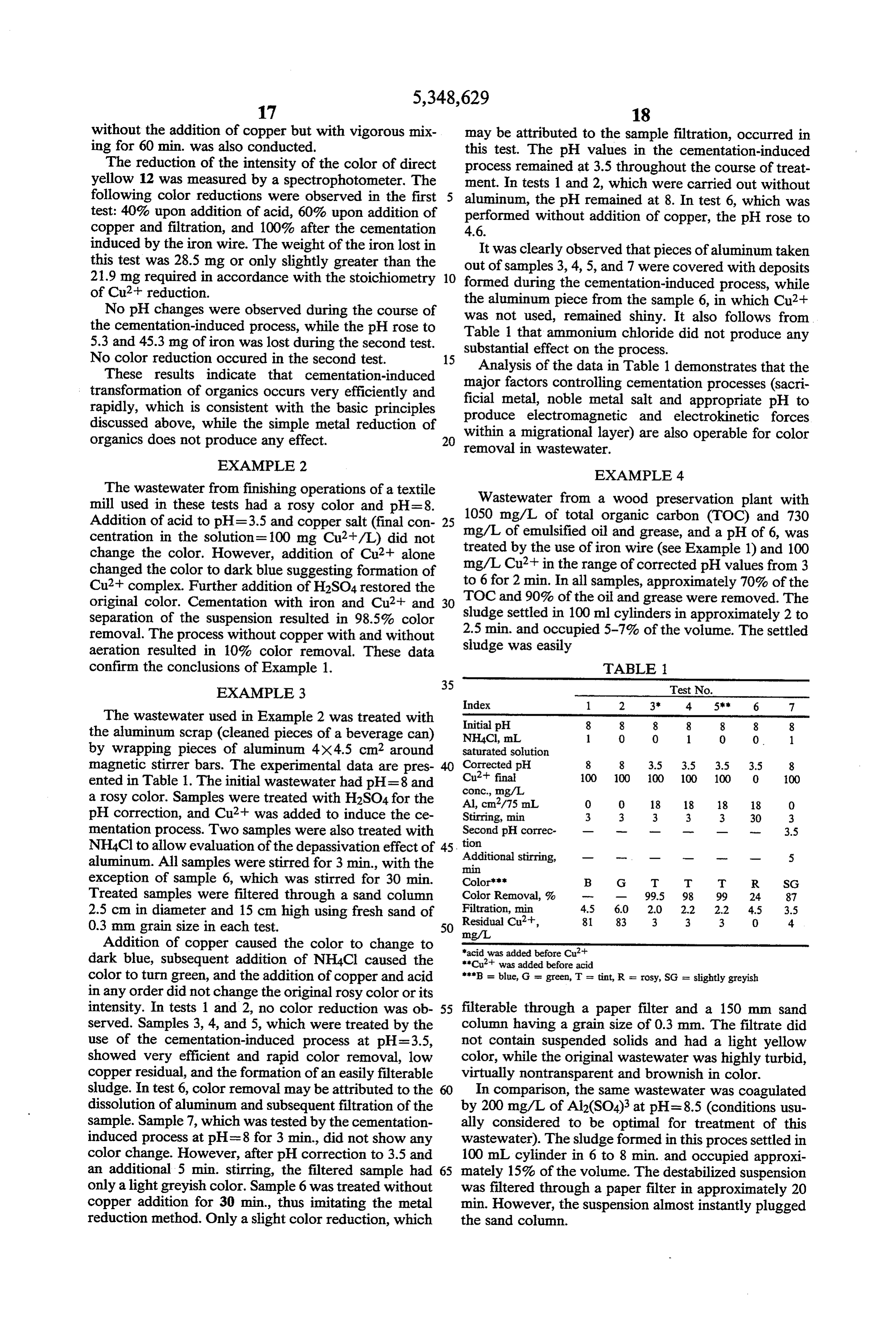
The wastewater used in Example 2 was treated with Initial pH 8 8 8 8 8 8 8 the aluminum scrap (cleaned pieces of a beverage can) NH4C, mL 1 O O 1 0 0. 1 by wrapping pieces of aluminum 4X4.5 cm around Saturated solution magnetic stirrer bars. The experimental data are pres Corrected pH 8 8 3.5 3.5 3.5 3.5 8 ented in Table 1. The initial wastewater had pH=8 and conc., mg/L.Cu2 final 100 OO 100 100 100 0 100 a rosy color. Samples were treated with H2SO4 for the Al, cm/75 mL O 0 18 18 18 18 O pH correction, and Cu2+ was added to induce the ce Stirring, min 3 3 3 3 3 30 3 mentation process. Two samples were also treated with tion Second pH correc- - W - m- - w 3.5
NH4Cl to allow evaluation of the depassivation effect of 45. Additional stirring, - - - o - m 5 aluminum. All samples were stirred for 3 min., with the min exception of sample 6, which was stirred for 30 min. Colors: B G T T T R SG Treated samples were filtered through a sand column Color Removal, 9% - 99.5 98 99 24 87 2.5 cm in diameter and 15 cm high using fresh sand of ResidualFiltration, min 4.5 6.0 2.0 2.2 2.2 4.5 3.5 0.3 mm grain size in each test. 50 mg/L. Cu2+, 81 83 3 3 3 0. 4. Addition of copper caused the color to change to "acid was added before Cut dark blue, subsequent addition of NH4Cl caused the "Cut was added before acid color to turn green, and the addition of copper and acid "B = blue, G = green, T = tint, R = rosy, SG = slightly greyish in any order did not change the original rosy color or its intensity. In tests 1 and 2, no color reduction was ob 55 filterable through a paper filter and a 150 mm sand served. Samples 3, 4, and 5, which were treated by the column having a grain size of 0.3 mm. The filtrate did use of the cementation-induced process at pH=3.5, not contain suspended solids and had a light yellow showed very efficient and rapid color removal, low color, while the original wastewater was highly turbid, copper residual, and the formation of an easily filterable virtually nontransparent and brownish in color. sludge. In test 6, color removal may be attributed to the In comparison, the same wastewater was coagulated dissolution of aluminum and subsequent filtration of the by 200 mg/L of Al2(SO4)3 at pH=8.5 (conditions usu sample. Sample 7, which was tested by the cementation ally considered to be optimal for treatment of this induced process at pH=8 for 3 min, did not show any wastewater). The sludge formed in this processettled in color change. However, after pH correction to 3.5 and 100 mL cylinder in 6 to 8 min. and occupied approxi an additional 5 min. stirring, the filtered sample had 65 mately 15% of the volume. The destabilized suspension only a lightgreyish color. Sample 6 was treated without was filtered through a paper filter in approximately 20 copper addition for 30 min, thus imitating the metal min. However, the suspension almost instantly plugged reduction method. Only a slight color reduction, which the sand column.
Page 20
Additionally, gas chromatograms of the filtered 8. The method of claim 7, which further comprises water samples treated by the use of the cementation the step of adding noble metal ions periodically by in induced process (FIG. 18), and by aluminum salt coagul jection through said permeable cathodic material. lation (FIG. 17) demonstrate that the number and the 9. The method of claim 7, which further comprises concentrations of organics remaining in water after the 5 the step of adding noble metal ions continuously by cementation-induced process are substantially lower injection through said permeable cathodic material. than those found after coagulation. 10. The method of claim 3, wherein said sacrificial Example 4 confirms the findings of the previous ex metal comprises fluidized particles.
amples and additionally demonstrates the usefulness of 10 11. The method of claim 1, wherein said induction this treatment with emulsion-containing wastewaters. step comprises applying high current density from an The better filterability of the sludge formed from the external electric source to said at least one cathode to cementation-induced process can be attributed to the create a migrational regime.
electrokinetic forces within the migrational layer. The 12. The method of claim 11, wherein said external description of the process and the above examples dem 15 electric source is comprised of pulses of current. onstrate that the migrational regime of the instant in 13. The method of claim 11, wherein said method is vention for the electrochemical treatment of materials is carried out in a compartmentalized reactor having a substantially faster and more efficient than known pro catholytic and an anolytic compartment separated by a CSSeS. membrane and having said at least one cathode and a While the invention has been described in detail with 20 first anode of said at least one anode in said catholytic particular reference to preferred embodiments thereof, compartment and a second anode of said at least one it will be understood that variations and modifications anode in said anolytic compartment, which further can be effected within the spirit and scope of the inven comprises the step of dialyzing said electrolyte by ap tion as previously described and as defined by the plying a polarizing current, said at least one cathode and claims. For example, various combinations of the de 25 said second anode connected to a source of said polariz scribed embodiments can be used, reactors can be oper ing current and said at least one cathode and said first ated under elevated pressure and/or temperature, and anode connected to a source of pulsed current. various external electrical circuits can be used to emu 14. The method of claim 13, wherein said membrane late the migrational regime. is an ion exchange membrane.
What is claimed is: 30 15. The method of claim 13, wherein said membrane 1. A method for the electrochemical processing of is a liquid permeable membrane. materials which comprises the steps of: 16. The method of claim 13, wherein filaments pro a) contacting an electrolyte containing the material to trude from the surface of said first anode. be processed with an electrode system comprising 17. The method of claim 13, wherein filaments pro at least one anode and at least one cathode, wherein 35 trude from the surface of said cathode. said material to be processed comprises an aqueous 18. The method of claim 11, wherein said method is solution or emulsion or suspension: and carried out in a compartmentalized reactor with a cath b) inducing a migrational regime such that a migra olytic and an anolytic compartment separated by a tional transport layer is formed at said at least one membrane and having said cathode in said catholytic cathode to provide a local electromagnetic field, compartment and said anode in said anolytic compart wherein said local electromagnetic field is capable ment, further comprising the step of dialyzing the elec of producing electromagnetic and electrokinetic trolyte by applying a polarizing current, said anode forces to effect said processing of material. having filaments protruding across said membrane into 2. The method of claim 1, wherein said induction step 45 said catholytic compartment and said cathode and said comprises creating a migrational regime cementation anode connected to a source of said polarizing current System. and a source of pulsed current. 3. The method of claim 2, wherein said electrode 19. The method of claim 18, wherein said membrane system comprises a sacrificial metal submerged in said is an electroneutral porous membrane. electrolyte and said electrolyte comprises a salt of a 20. The method of claim 18, wherein said membrane second metal that is more noble than said sacrificial is an ion exchange membrane.
metal. 21. The method of claim 18, wherein filaments pro 4. The method of claim 3, wherein the surface area of trude from said cathode.
said at least one cathode is increased by connecting a 22. The method of claim 1, wherein said induction cathodic material more noble than said sacrificial metal 55 step comprises creating a cementation system and ap to said sacrificial metal. plying high current density from an external electric 5. The method of claim 4, wherein said sacrificial source to said at least one cathode to create said migra metal and said cathodic material are submerged in sepa tional regime.
rate compartments such that said sacrificial metal com 23. The method of claim 1, wherein the intensity of partment contains a cementation electrolyte and said 60 said local electromagnetic field is increased by the addi cathodic material compartment contains said electro tion of an indifferent ion to said electrolyte. lyte containing the material to be processed. 24. The method of claim 1, wherein the intensity of 6. The method of claim 5, wherein said sacrificial said local electromagnetic field is increased by the addi metal compartment and said cathodic material compart tion of a promoter capable of being reduced at the outer ment are separated by a membrane comprising said 65 boundary of said migrational layer.
cathodic material. 25. The method of claim 24, wherein said promoter is 7. The method of claim 4, wherein said cathodic selected from the group consisting of Cr2O72 and material is permeable to liquids. VO43-.
Page 21
26. The method of claim 1, wherein the intensity of 38. The method of claim 37, wherein said noble metal said local electromagnetic field is increased by the addi particles comprise cemented noble metal particles. tion of a complexing agent to said electrolyte. 39. The method of claim 1, which further comprises 27. The method of claim 1, wherein the intensity of the step of adding noble ions continuously to said elec said local electromagnetic field is increased by increas 5 trolyte.
ing the temperature of said electrolyte. 40. The method of claim 1, which further comprises 28. The method of claim 1, wherein the intensity of the step of adding noble ions periodically to said elec said local electromagnetic field is increased by the addi trolyte.
tion of an anion to said electrolyte. 41. The method of claim 1, wherein said at least one 29. The method of claim 1, wherein the intensity of 10 cathode is permeable to liquids.
said local electromagnetic field is increased by optimiz 42. The method of claim 41, which further comprises ing the mixing rate of said electrolyte. the step of adding noble ions to said electrolyte by injec 30. The method of claim 1, wherein said at least one tion through said permeable cathode.
cathode possesses a rough surface to increase the inten 43. The method of claim 1, wherein said material to sity of said local electromagnetic field. 15 be processed comprises organic material. 31. The method of claim 1, wherein said electrolyte 44. The method claim 1, wherein said material to be contains organic compounds. processed comprises wastewater. 32. The method of claim 1, wherein said electrolyte 45. The method of claim 1, wherein said electrochem contains suspended or emulsified particles. ical processing of materials comprises oxidation or re 33. The method of claim 1, wherein said electrolyte 20 duction of said material to be processed. comprises a mixture of noble metal ion species. 46. The method of claim 1, wherein said electrochem 34. The method of claim 1, wherein said electrolyte ical processing of materials comprises dimerization or comprises a mixture of indifferent ions. polymerization of said material to be processed. 35. The method of claim 1, wherein said electrolyte 47. The method of claim 1, wherein said electrochem comprises a mixture of anions. 25 ical processing of materials comprises coagulation of 36. The method of claim 1, wherein said steps are mineral or organic suspended particles or emulsions. performed in the presence of a reducing atmosphere. 48. The method of claim 1, wherein said electrochem 37. The method of claim 1, and further comprising ical processing of materials comprises the inactivation the step of adding fluidized noble metal particles to said or killing of microorganisms.
electrolyte. 30 k ak sk :
Provenance
- Collection
- Cited prior art
- Original PDF
- patentimages.storage.googleapis.com →
- Filed
- 1991-02-05
- Pages
- 21
- Method
- pdftotext (the PDF's own text layer) + pdftoppm 300dpi page scans
- Source
- Google Patents bibliographic record
- Granted
- 1994-09-20
- Inventors
- Boris M. Khudenko
- Transcribed from
- patentimages.storage.googleapis.com →