patent · US4056452
Electrolysis apparatus
1 November 1977
Page 1 — bibliographic record
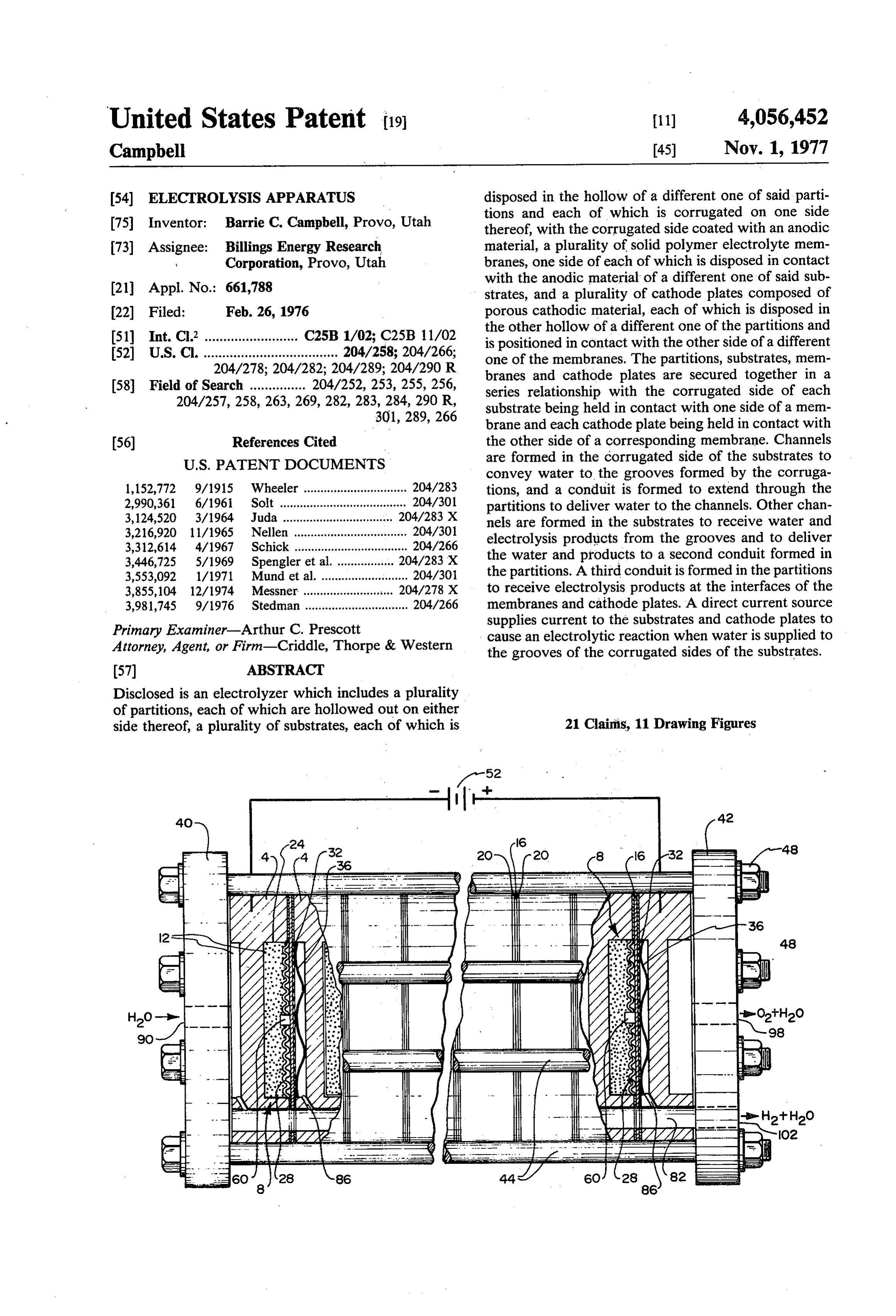
United States Patent (19) 11) 4,056,452 Campbell 45) Nov. 1, 1977 54 ELECTROLYSIS APPARATUS disposed in the hollow of a different one of said parti 75 Inventor: Barrie C. Campbell, Provo, Utah tions and each of which is corrugated on one side thereof, with the corrugated side coated with an anodic 73) Assignee: Billings Energy Research material, a plurality of solid polymer electrolyte mem Corporation, Provo, Utah branes, one side of each of which is disposed in contact with the anodic material of a different one of said sub (21) Appl. No.: 661,788 strates, and a plurality of cathode plates composed of 22 Filed: Feb. 26, 1976 porous cathodic material, each of which is disposed in the other hollow of a different one of the partitions and 51 Int. C.’......................... C25B 1/02; C25B 11/02 is positioned in contact with the other side of a different 52 U.S. C. .................................... 204/258; 204/266; one of the membranes. The partitions, substrates, mem 204/278; 204/282; 204/289; 204/290 R branes and cathode plates are secured together in a 58 Field of Search ............... 204/252, 253, 255, 256, series relationship with the corrugated side of each 204/257, 258, 263,269,282, 283, 284, 290 R, substrate being held in contact with one side of a mem 301, 289, 266 brane and each cathode plate being held in contact with 56) References Cited the other side of a corresponding membrane. Channels
convey water to the grooves formed by the corruga 1,152,772 9/1915 Wheeler ............................... 204/283 tions, and a conduit is formed to extend through the 2,990,361 6/1961 Solt ...................................... 204/301 partitions to deliver water to the channels. Other chan 3,124,520 3/1964. Juda ................................. 204/283 X nels are formed in the substrates to receive water and 3,216,920 1 1/1965 Nellen .................................. 204/301 electrolysis products from the grooves and to deliver 3,312,614 4/1967 Schick .................................. 204/266 3,446,725 5/1969 Spengler et al. ......... ... 204/283 X the water and products to a second conduit formed in 3,553,092 1/1971 Mund et al. .......................... 204/30 the partitions. A third conduit is formed in the partitions 3,855,104 12/1974 Messner ....... 204/278 X to receive electrolysis products at the interfaces of the 3,981,745 9/1976 Stedman ............................... 204/266 membranes and cathode plates. A direct current source Primary Examiner-Arthur C. Prescott supplies current to the substrates and cathode plates to Attorney, Agent, or Firm-Criddle, Thorpe & Western cause an electrolytic reaction when water is supplied to the grooves of the corrugated sides of the substrates.
Disclosed is an electrolyzer which includes a plurality of partitions, each of which are hollowed out on either side thereof, a plurality of substrates, each of which is 21 Clairis, 11 Drawing Figures
Page 2
Drawing sheet — no readable text.
Page 3
Drawing sheet — no readable text.
Page 4
pair of electrodes disposed on either side of and in
ELECTROLYSS APPARATUS contact with the membrane. At least one of the elec BACKGROUND OF THE INVENTION trodes includes a corrugated portion which presents alternating ridges and grooves. The top of the ridges are
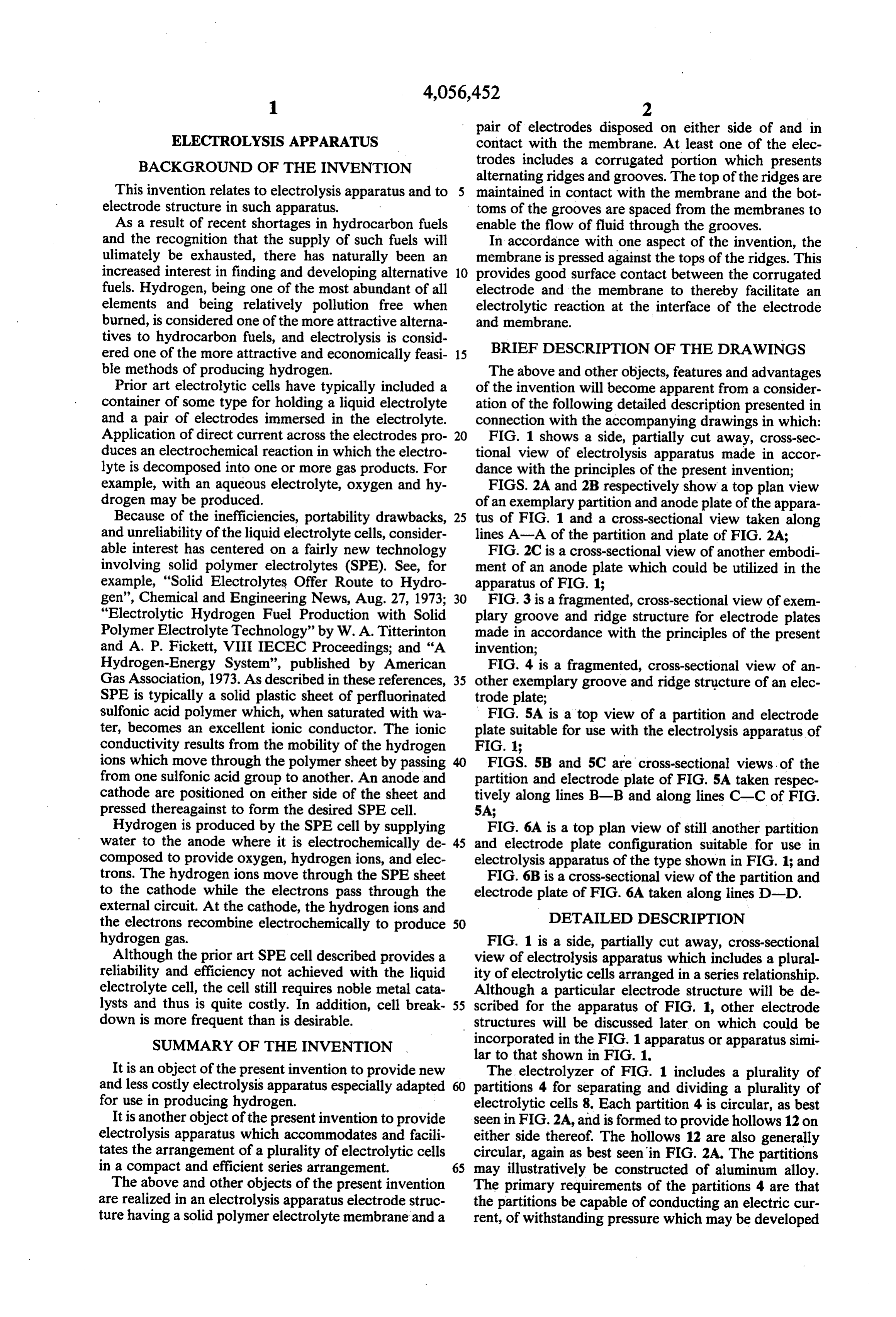
This invention relates to electrolysis apparatus and to maintained in contact with the membrane and the bot electrode structure in such apparatus. toms of the grooves are spaced from the membranes to As a result of recent shortages in hydrocarbon fuels enable the flow of fluid through the grooves. and the recognition that the supply of such fuels will In accordance with one aspect of the invention, the ulimately be exhausted, there has naturally been an membrane is pressed against the tops of the ridges. This increased interest in finding and developing alternative 10 provides good surface contact between the corrugated fuels. Hydrogen, being one of the most abundant of all electrode and the membrane to thereby facilitate an elements and being relatively pollution free when electrolytic reaction at the interface of the electrode burned, is considered one of the more attractive alterna and membrane.
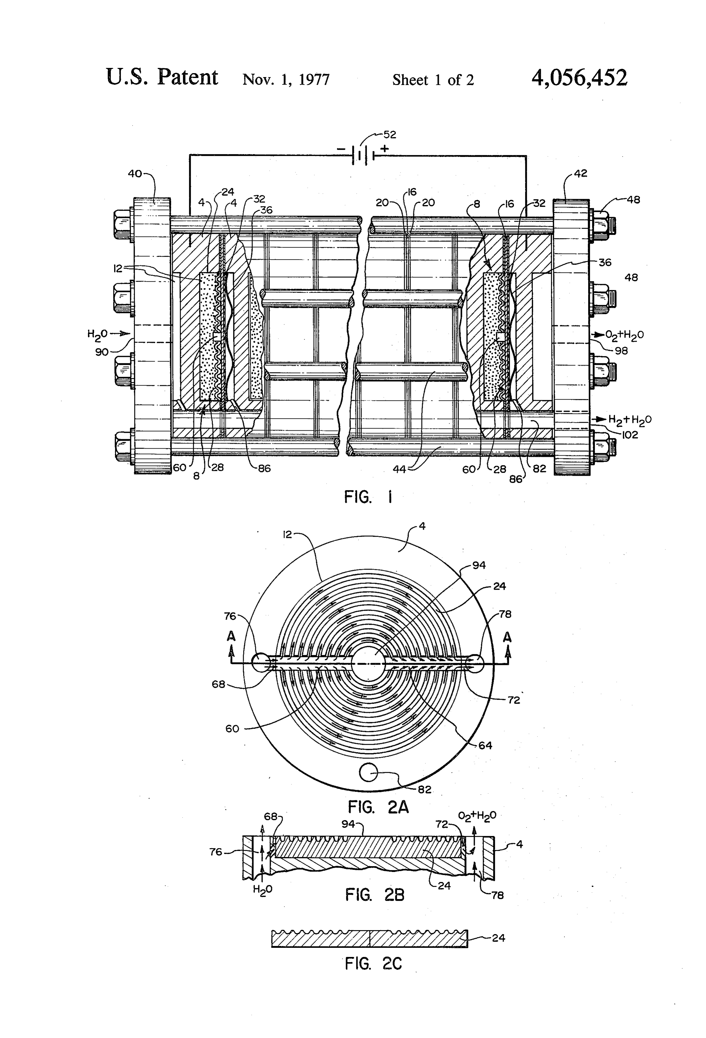
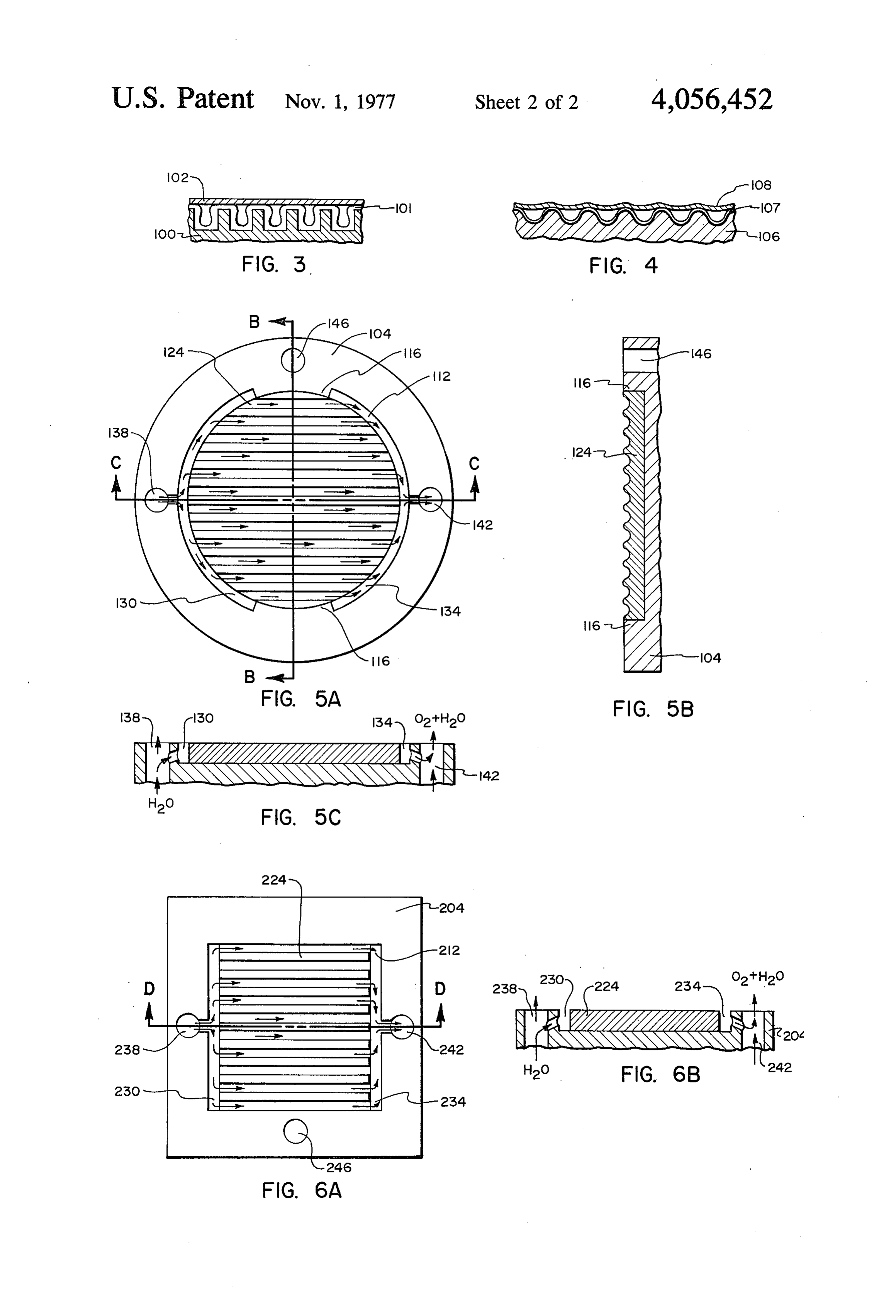
tives to hydrocarbon fuels, and electrolysis is consid ered one of the more attractive and economically feasi 15 BRIEF DESCRIPTION OF THE DRAWINGS ble methods of producing hydrogen. The above and other objects, features and advantages Prior art electrolytic cells have typically included a of the invention will become apparent from a consider container of some type for holding a liquid electrolyte ation of the following detailed description presented in and a pair of electrodes immersed in the electrolyte. connection with the accompanying drawings in which: Application of direct current across the electrodes pro 20 FIG. 1 shows a side, partially cut away, cross-sec duces an electrochemical reaction in which the electro tional view of electrolysis apparatus made in accore lyte is decomposed into one or more gas products. For dance with the principles of the present invention; example, with an aqueous electrolyte, oxygen and hy FIGS. 2A and 2B respectively show a top plan view drogen may be produced. of an exemplary partition and anode plate of the appara Because of the inefficiencies, portability drawbacks, 25 tus of FIG. 1 and a cross-sectional view taken along and unreliability of the liquid electrolyte cells, consider lines A-A of the partition and plate of FIG. 2A; able interest has centered on a fairly new technology FIG. 2C is a cross-sectional view of another embodi involving solid polymer electrolytes (SPE). See, for ment of an anode plate which could be utilized in the example, "Solid Electrolytes Offer Route to Hydro apparatus of FIG. 1;
gen', Chemical and Engineering News, Aug. 27, 1973; 30 FIG. 3 is a fragmented, cross-sectional view of exem "Electrolytic Hydrogen Fuel Production with Solid plary groove and ridge structure for electrode plates Polymer Electrolyte Technology” by W. A. Titterinton made in accordance with the principles of the present and A. P. Fickett, VIII IECEC Proceedings; and "A invention;
Hydrogen-Energy System', published by American FIG. 4 is a fragmented, cross-sectional view of an Gas Association, 1973. As described in these references, 35 other exemplary groove and ridge structure of an elec SPE is typically a solid plastic sheet of perfluorinated trode plate;
sulfonic acid polymer which, when saturated with wa FIG. 5A is a top view of a partition and electrode ter, becomes an excellent ionic conductor. The ionic plate suitable for use with the electrolysis apparatus of conductivity results from the mobility of the hydrogen FIG. 1;
ions which move through the polymer sheet by passing FIGS. 5B and 5C are cross-sectional views, of the from one sulfonic acid group to another. An anode and partition and electrode plate of FIG. 5A taken respec cathode are positioned on either side of the sheet and tively along lines B-B and along lines C-C of FIG. pressed thereagainst to form the desired SPE cell. 5A;
Hydrogen is produced by the SPE cell by supplying FIG. 6A is a top plan view of still another partition water to the anode where it is electrochemically de 45 and electrode plate configuration suitable for use in composed to provide oxygen, hydrogen ions, and elec electrolysis apparatus of the type shown in FIG. 1; and trons. The hydrogen ions move through the SPE sheet FIG. 6B is a cross-sectional view of the partition and to the cathode while the electrons pass through the electrode plate of FIG. 6A taken along lines D-D. external circuit. At the cathode, the hydrogen ions and DETAILED DESCRIPTION the electrons recombine electrochemically to produce 50 hydrogen gas. FIG. 1 is a side, partially cut away, cross-sectional Although the prior art SPE cell described provides a view of electrolysis apparatus which includes a plural reliability and efficiency not achieved with the liquid ity of electrolytic cells arranged in a series relationship. electrolyte cell, the cell still requires noble metal cata Although a particular electrode structure will be de lysts and thus is quite costly. In addition, cell break 55 scribed for the apparatus of FIG. 1, other electrode down is more frequent than is desirable. structures will be discussed later on which could be SUMMARY OF THE INVENTION incorporated in the FIG. 1 apparatus or apparatus simi lar to that shown in FIG. 1.
It is an object of the present invention to provide new The electrolyzer of FIG. 1 includes a plurality of and less costly electrolysis apparatus especially adapted partitions 4 for separating and dividing a plurality of for use in producing hydrogen. electrolytic cells 8. Each partition 4 is circular, as best It is another object of the present invention to provide seen in FIG. 2A, and is formed to provide hollows 12 on electrolysis apparatus which accommodates and facili either side thereof. The hollows 12 are also generally tates the arrangement of a plurality of electrolytic cells circular, again as best seen in FIG. 2A. The partitions in a compact and efficient series arrangement. 65 may illustratively be constructed of aluminum alloy. The above and other objects of the present invention The primary requirements of the partitions 4 are that are realized in an electrolysis apparatus electrode struc the partitions be capable of conducting an electric cur ture having a solid polymer electrolyte membrane and a rent, of withstanding pressure which may be developed
Page 5
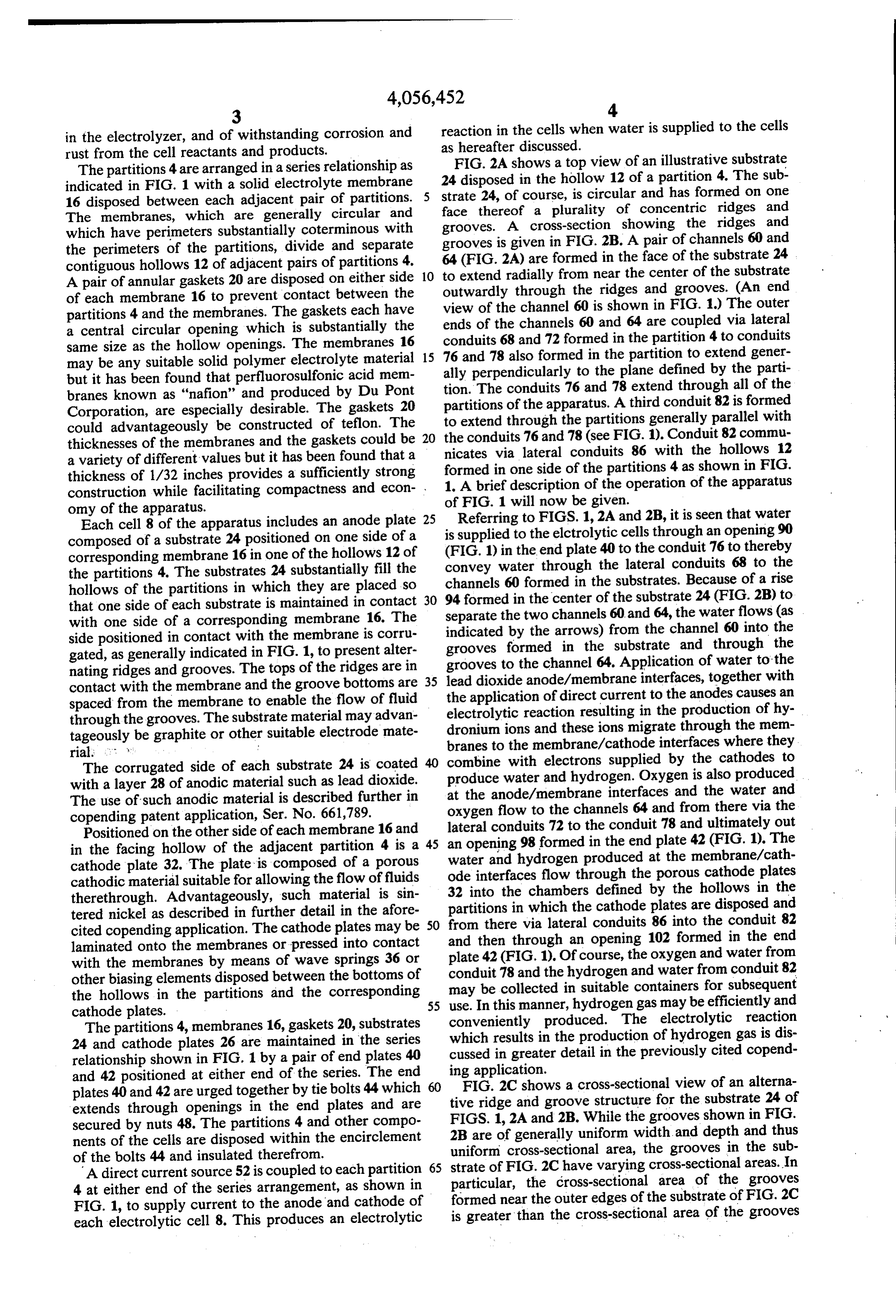
in the electrolyzer, and of withstanding corrosion and reaction in the cells when water is supplied to the cells rust from the cell reactants and products. as hereafter discussed.
The partitions 4 are arranged in a series relationship as FIG. 2A shows a top view of an illustrative substrate indicated in FIG. 1 with a solid electrolyte membrane 24 disposed in the hollow 12 of a partition 4. The sub strate 24, of course, is circular and has formed on one 16 disposed between each adjacent pair of partitions.
The membranes, which are generally circular and face thereof a plurality of concentric ridges and grooves. A cross-section showing the ridges and which have perimeters substantially coterminous with grooves is given in FIG. 2B. A pair of channels 60 and the perimeters of the partitions, divide and separate contiguous hollows 12 of adjacent pairs of partitions 4. 64 (FIG. 2A) are formed in the face of the substrate 24 A pair of annular gaskets 20 are disposed on either side 10 to extend radially from near the center of the substrate of each membrane 16 to prevent contact between the view of thethrough outwardly the ridges and grooves. (An end partitions 4 and the membranes. The gaskets each have ends of the channels6060isand channel shown in FIG. 1.) The outer a central circular opening which is substantially the conduits 68 and 72 formed in 64 are coupled via lateral same size as the hollow openings. The membranes 16 15 76 and 78 also formed in the the partition 4 to conduits partition to extend gener may be any suitable solid polymer electrolyte material but it has been found that perfluorosulfonic acid mem ally perpendicularly to the plane defined by the parti branes known as "nafion' and produced by Du Pont tion. The conduits 76 and 78 extend through all of the partitions of the apparatus. A third conduit 82 is formed
Corporation, are especially desirable. The gaskets 20 to extend through the partitions generally parallel with could advantageously be constructed of teflon. The thicknesses of the membranes and the gaskets could be 20 the conduits 76 and 78 (see FIG. 1). Conduit 82 commu nicates via lateral conduits 86 with the hollows 12 a variety of different values but it has been found that a thickness of 1/32 inches provides a sufficiently strong formed in one side of the partitions 4 as shown in FIG. construction while facilitating compactness and econ 1. A brief description of the operation of the apparatus omy of the apparatus. of FIG. 1 will now be given.
Referring to FIGS. 1, 2A and 2B, it is seen that water
Each cell 8 of the apparatus includes an anode plate 25 is supplied composed of a substrate 24 positioned on one side of a to the elctrolytic cells through an opening 90 (FIG.
corresponding membrane 16 in one of the hollows 12 of convey water 1) in the end plate 40 to the conduit 76 to thereby the partitions 4. The substrates 24 substantially fill the channels 60 formed through the lateral conduits 68 to the hollows of the partitions in which they are placed so in the substrates. Because of a rise that one side of each substrate is maintained in contact 30 94 formed in the center of the substrate 24 (FIG. 2B) to with one side of a corresponding membrane 16. The separate the two channels 60 and 64, the water flows (as side positioned in contact with the membrane is corru indicated formed by the arrows) from the channel 60 into the gated, as generally indicated in FIG. 1, to present alter grooves in the substrate and through the nating ridges and grooves. The tops of the ridges are in grooves to the channel 64. Application of water to the contact with the membrane and the groove bottoms are 35 the lead dioxide anode/membrane interfaces, together with spaced from the membrane to enable the flow of fluid electrolytic application of direct current to the anodes causes an through the grooves. The substrate material may advan dronium ionsreaction and resulting in the production of hy these ions migrate through the mem tageously be graphite or other suitable electrode mate branes to the membrane/cathode interfaces where they
The corrugated side of each substrate 24 is coated 40 combine with electrons supplied by the cathodes to with a layer 28 of anodic material such as lead dioxide. produce water and hydrogen. Oxygen is also produced at the anode/membrane interfaces and the water and
The use of such anodic material is described further in copending patent application, Ser. No. 661,789. oxygen flow to the channels 64 and from there via the Positioned on the other side of each membrane 16 and lateral conduits 72 to the conduit 78 and ultimately out in the facing hollow of the adjacent partition 4 is a 45 an opening 98 formed in the end plate 42 (FIG. 1). The water and hydrogen produced at the membrane/cath cathode plate 32. The plate is composed of a porous ode interfaces flow through the porous cathode plates cathodic material suitable for allowing the flow of fluids 32 into therethrough. Advantageously, such material is sin partitionsthein which chambers defined by the hollows in the the cathode plates are disposed and tered nickel as described in further detail in the afore from there via lateral cited copending application. The cathode plates may be and then through an opening 50 conduits 86 into the conduit 82 laminated onto the membranes or pressed into contact plate 42 (FIG. 1). Of course, the102 formed in the end oxygen and water from with the membranes by means of wave springs 36 or conduit 78 and the hydrogen and water from conduit 82 other biasing elements disposed between the bottoms of the hollows in the partitions and the corresponding may be collected in suitable containers for subsequent cathode plates. 55 use. In this manner, hydrogen gas may be efficiently and conveniently produced. The electrolytic reaction
The partitions 4, membranes 16, gaskets 20, substrates which 24 and cathode plates 26 are maintained in the series cussed results in the production of hydrogen gas is dis in greater detail in the previously cited copend relationship shown in FIG. 1 by a pair of end plates 40 ing application.
and 42 positioned at either end of the series. The end plates 40 and 42 are urged together by tie bolts 44 which 60 tiveFIG. 2C shows a cross-sectional view of an alterna ridge and groove structure for the substrate 24 of extends through openings in the end plates and are FIGS. 1, 2A and 2B. While the grooves shown in FIG. secured by nuts 48. The partitions 4 and other compo 2B are of generally uniform width, and depth and thus nents of the cells are disposed within the encirclement uniform cross-sectional area, the grooves in the sub of the bolts 44 and insulated therefrom.
A direct current source 52 is coupled to each partition 65 strate of FIG. 2Chave varying cross-sectional areas. In particular, the cross-sectional area of the grooves 4 at either end of the series arrangement, as shown in formed near the outer edges of the substrate of FIG. 2C FIG. 1, to supply current to the anode and cathode of is greater than the cross-sectional area of the grooves each electrolytic cell 8. This produces an electrolytic
Page 6
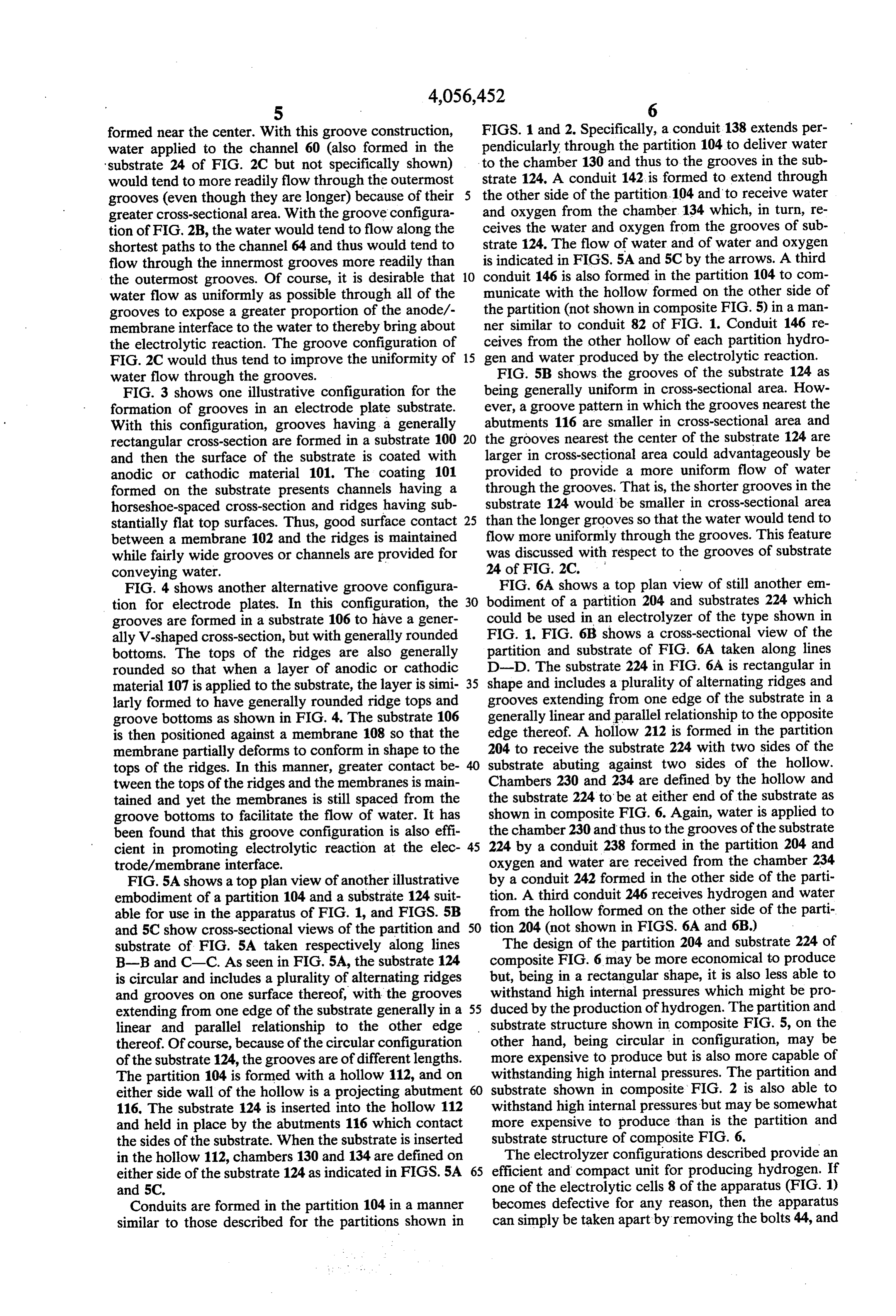
formed near the center. With this groove construction, FIGS. 1 and 2. Specifically, a conduit 138 extends per water applied to the channel 60 (also formed in the pendicularly through the partition 104 to deliver water substrate 24 of FIG. 2C but not specifically shown) to the chamber 130 and thus to the grooves in the sub would tend to more readily flow through the outermost strate 124. A conduit 142 is formed to extend through grooves (even though they are longer) because of their the other side of the partition. 104 and to receive water greater cross-sectional area. With the groove configura and oxygen from the chamber 134 which, in turn, re tion of FIG. 2B, the water would tend to flow along the ceives the water and oxygen from the grooves of sub shortest paths to the channel 64 and thus would tend to strate 124. The flow of water and of water and oxygen flow through the innermost grooves more readily than is indicated in FIGS. 5A and 5C by the arrows. A third the outermost grooves. Of course, it is desirable that 10 conduit 146 is also formed in the partition 104 to com water flow as uniformly as possible through all of the municate with the hollow formed on the other side of grooves to expose a greater proportion of the anode/- the partition (not shown in composite FIG. 5) in a man membrane interface to the water to thereby bring about ner similar to conduit 82 of FIG. 1. Conduit 146 re the electrolytic reaction. The groove configuration of ceives from the other hollow of each partition hydro FIG. 2C would thus tend to improve the uniformity of 15 gen and water produced by the electrolytic reaction. water flow through the grooves. FIG. 5B shows the grooves of the substrate 124 as FIG. 3 shows one illustrative configuration for the being generally uniform in cross-sectional area. How formation of grooves in an electrode plate substrate. ever, a groove pattern in which the grooves nearest the With this configuration, grooves having a generally abutments 116 are smaller in cross-sectional area and rectangular cross-section are formed in a substrate 100 20 the grooves nearest the center of the substrate 124 are and then the surface of the substrate is coated with larger in cross-sectional area could advantageously be anodic or cathodic material 101. The coating 101 provided to provide a more uniform flow of water formed on the substrate presents channels having a through the grooves. That is, the shorter grooves in the horseshoe-spaced cross-section and ridges having sub substrate 124 would be smaller in cross-sectional area stantially flat top surfaces. Thus, good surface contact 25 than the longer grooves so that the water would tend to between a membrane 102 and the ridges is maintained flow more uniformly through the grooves. This feature while fairly wide grooves or channels are provided for was discussed with respect to the grooves of substrate conveying water. 24 of FIG. 2C.
FIG. 4 shows another alternative groove configura FIG. 6A shows a top plan view of still another em tion for electrode plates. In this configuration, the 30 bodiment of a partition 204 and substrates 224 which grooves are formed in a substrate 106 to have a gener could be used in an electrolyzer of the type shown in ally V-shaped cross-section, but with generally rounded FIG. 1. FIG. 6B shows a cross-sectional view of the bottoms. The tops of the ridges are also generally partition and substrate of FIG. 6A taken along lines rounded so that when a layer of anodic or cathodic D-D. The substrate 224 in FIG. 6A is rectangular in material 107 is applied to the substrate, the layer is simi 35 shape and includes a plurality of alternating ridges and larly formed to have generally rounded ridge tops and grooves extending from one edge of the substrate in a groove bottoms as shown in FIG. 4. The substrate 106 generally linear and parallel relationship to the opposite is then positioned against a membrane 108 so that the edge thereof. A hollow 212 is formed in the partition membrane partially deforms to conform in shape to the 204 to receive the substrate 224 with two sides of the tops of the ridges. In this manner, greater contact be substrate abuting against two sides of the hollow. tween the tops of the ridges and the membranes is main Chambers 230 and 234 are defined by the hollow and tained and yet the membranes is still spaced from the the substrate 224 to be at either end of the substrate as groove bottoms to facilitate the flow of water. It has shown in composite FIG. 6. Again, water is applied to been found that this groove configuration is also effi the chamber 230 and thus to the grooves of the substrate cient in promoting electrolytic reaction at the elec 45 224 by a conduit 238 formed in the partition 204 and trode/membrane interface. oxygen and water are received from the chamber 234 FIG. 5A shows a top plan view of another illustrative by a conduit 242 formed in the other side of the parti embodiment of a partition 104 and a substrate 124 suit tion. A third conduit 246 receives hydrogen and water able for use in the apparatus of FIG. 1, and FIGS. 5B from the hollow formed on the other side of the parti and 5C show cross-sectional views of the partition and 50 tion 204 (not shown in FIGS. 6A and 6B.) substrate of FIG. 5A taken respectively along lines The design of the partition 204 and substrate 224 of B-B and C-C. As seen in FIG. 5A, the substrate 124 composite FIG. 6 may be more economical to produce is circular and includes a plurality of alternating ridges but, being in a rectangular shape, it is also less able to and grooves on one surface thereof, with the grooves withstand high internal pressures which might be pro extending from one edge of the substrate generally in a 55 duced by the production of hydrogen. The partition and linear and parallel relationship to the other edge substrate structure shown in composite FIG. 5, on the thereof. Of course, because of the circular configuration other hand, being circular in configuration, may be of the substrate 124, the grooves are of different lengths. more expensive to produce but is also more capable of The partition 104 is formed with a hollow 112, and on withstanding high internal pressures. The partition and either side wall of the hollow is a projecting abutment 60 substrate shown in composite FIG. 2 is also able to 116. The substrate 124 is inserted into the hollow 112 withstand high internal pressures but may be somewhat and held in place by the abutments 116 which contact more expensive to produce than is the partition and the sides of the substrate. When the substrate is inserted substrate structure of composite FIG. 6. in the hollow 112, chambers 130 and 134 are defined on The electrolyzer configurations described provide an either side of the substrate 124 as indicated in FIGS. 5A 65 efficient and compact unit for producing hydrogen. If and 5C. one of the electrolytic cells 8 of the apparatus (FIG. 1) Conduits are formed in the partition 104 in a manner becomes defective for any reason, then the apparatus similar to those described for the partitions shown in can simply be taken apart by removing the bolts 44, and
Page 7
then removing and replacing the defective elements. allel relationship and in contact with the other side The apparatus is thus economical to maintain. of a different one of said membranes, It is to be understood that the above-described ar means defining chambers about each cathode plate rangement is only illustrative of the application of the into which may flow gas products produced at the principles of the present invention. Numerous other interfaces of the membranes and cathode plates, modifications and alternative arrangements may be means for securing the substrates, membranes and devised by those skilled in the art without departing cathode plates in a series relationship, from the spirit and scope of the present invention and means for conveying water to the grooves located on the appended claims are intended to cover such modifi 10 each substrate, cations and arrangements. means for applying a D.C. current to the substrates What is claimed is: and the cathode plates, 1. An electrode structure for electrolysis apparatus first means for receiving water and products pro having a solid polymer electrolyte membrane and a pair duced at the interfaces of the membranes and an of electrodes disposed on either side of and in contact 15 odic material, and with the membrane, at least one of said electrodes in second means for receiving products produced at the cluding a corrugated surface portion which presents interfaces of the membranes and cathode plates. alternating ridges and grooves, with the ridges being stratesAnareelectrolyzer
maintained in contact with the membrane so that the grooves extend from near one edgeand generally rectangular
said ridges and the substrates to portions of the membrane in contact with the ridges are 20 near the opposite edge thereof, deformed to conform in shape to the tops of the ridges wherein said water conveying means comprises and the grooved bottoms being spaced from the mem means defining a plurality of first channels, each brane to enable the flow of fluid through the grooves, extending generally perpendicularly to the ridges said corrugated surface portion extending over a gener and grooves of a corresponding substrate at one end ally circular area and in a substantially flat plane. 25 thereof and adapted to convey water to such 2. An electrode structure as in claim 1 wherein the grooves, tops of the ridges and the bottoms of the grooves are wherein said first receiving means comprises means generally rounded defining a plurality of second channels, each ex 3. An electrode structure as in claim 1 wherein the tending generally perpendicularly to the ridges and tops of the ridges are generally flat, and wherein the 30 grooves of a corresponding substrate at the end grooves are formed to have a generally horseshoe thereof opposite the location of the first channels shaped cross-section. and adapted to receive water and products pro 4. An electrode structure as in claim 1 wherein the duced at the interfaces of the membranes and an grooves and ridges are disposed in a substantially linear odic material, and parallel relationship. 35 wherein said second receiving means comprises a 5. An electrode structure as in claim 4 wherein the plurality of third channels defined in the chamber cross-sectional area of the grooves extending through defining means to communicate with and receive the circular area near the center thereof is greater than from the chambers products produced at the inter the cross-sectional area of the grooves extending faces of the membranes and cathode plates. through the circular area near the edges thereof. 40 12. An electrolyzer as in claim 10 wherein said sub 6. An electrode structure as in claim 5 wherein the strates are generally circular and said ridges and cross-sectional area of each groove is proportional to its grooves extend from near one edge of the substrates to length. near the other edge thereof generally in a parallel rela 7. An electrode structure as in claim 1 wherein the tionship, ridges and grooves are formed concentrically in said 45 wherein said water conveying means comprises surface portion substantially about the center thereof. means defining a plurality of first channels, each 8. An electrode structure as in claim 7 wherein the extending adjacent the terminations of the ridges cross-sectional area of the grooves formed concentri and grooves of a corresponding substrate at said cally near the center of the circular area is less than the one edge thereof to convey water to the grooves, cross-sectional area of the grooves formed concentri 50 wherein said first receiving means comprises means cally near the edge of the circular area. defining a plurality of second channels, each ex 9. An electrode structure as in claim 8 wherein the tending adjacent the terminations of the ridges and cross-sectional area of each groove is proportional to grooves of a corresponding substrate at said other the distance of the groove from the center of the circu edge thereof to receive water and products pro lar area. 55 duced at the interfaces of the membranes and an 10. An electrolyzer comprising odic material, and a plurality of substrates, each formed with corruga wherein said second receiving means comprises a tions on one side thereof to present alternating plurality of third channels defined in the chamber ridges and grooves and each being coated on the defining means to communicate with and receive corrugated side with anodic material, said sub 60 from the chambers products produced at the inter strates being arranged in series so that the coated faces of the membranes and cathode plates. sides thereof face in the same direction, 13. An electrolyzer as in claim 12 wherein said cham a plurality of solid polymer electrolyte membranes, ber defining means comprises a plurality of partitions, one side of each of which is disposed in contact each disposed between a different substrate and cathode with the anodic material of a different one of said 65 plate and each having a generally planar profile and a substrates, hollow formed in either side thereof, one of such hol a plurality of cathode plates composed of porous lows being adapted to receive and hold a substrate and cathodic material, each disposed in a generally par the other of such hollows being adapted to receive and
Page 8
hold a cathode plate, said partitions being arranged in adapted to receive and hold a substrate and the other of series to maintain the anodic material of each substrate said hollows being adapted to receive and hold a cath and each cathode plate in contact with and on either ode plate, said partitions being arranged in a series rela side of a corresponding membrane. tionship to maintain the anodic material of each sub 14. An electrolyzer as in claim 13 wherein the cross strate and cathode plate in contact with and on either sectional areas of the longer grooves in the substrate are side of a corresponding membrane. greater than the cross-sectional areas of the shorter 18. An electrolyzer as in claim 17 wherein said water grooves.
conveying 15. An electrolyzer as in claim 10 wherein said sub formed to extend means further comprises first conduit means strates are generally circular and said ridges and 10 pendicularly therewith through the partitions generally per grooves are formed concentrically in the substrates, and to communicate with and convey water to wherein said water conveying means comprises a wherein said first receiving each of said first channel, means, plurality of first channel means, each formed in the second conduit means formedmeans to further comprises extend through the coated side of a different one of said substrates to partitions generally perpendicularly therewith extend from near the center of the substrate gener 15 communicate with and receive water and products and to ally radially outwardly through the ridges to the edge of the substrate to convey water to the corre from each of said second channel means, and wherein sponding grooves, said second receiving means further comprises third wherein said first receiving means comprises a plural conduit means formed to extend through the partitions ity of second channel means, each formed in the 20 generally perpendicularly therewith and to communi coated side of a different one of said substrates to cate with and receive products from each of said third extend from near the center of the substrate gener channel means.
ally radially outwardly through the ridges to the 19. An electrolyzer as in claim 18 wherein each first edge of the substrate to receive water and products and second channel means of a substrate are formed in from the corresponding grooves, each of said sec 25 the substrate at an angle of about 180° apart. ond channel means being spaced apart from the first 20. An electrolyzer as in claim 19 wherein said first, channel means on the corresponding substrate, and second and third conduit means extend through the wherein said second receiving means comprises a partitions at locations between the partition hollows plurality of third channel means formed in said and the outer edge of the partitions, wherein the first chamber defining means to communicate with and 30 and second channel means extend respectively from the receive products from the chambers. first and second conduit means toward the center of the 16. An electrolyzer as in claim 15 wherein the cross substrates, and wherein the third channel means extend sectional area of the grooves formed concentrically from the third conduit means into the hollow of each near the center of a substrate is less than the cross-sec partition in which is held the cathode plate. tional area of the outer-most grooves of the substrate. 35 21. An electrolyzer as in claim 17 further including a 17. An electrolyzer as in claim 14 wherein said cham plurality of biasing means disposed in each hollow in ber defining means comprises a plurality of partitions, which a cathode plate is held to force the cathode plates each formed to have a generally planar profile with a against the corresponding membranes. hollow in each side thereof, one of said hollows being k k k k k
Provenance
- Collection
- Cited prior art
- Original PDF
- patentimages.storage.googleapis.com →
- Filed
- 1976-02-26
- Pages
- 8
- Method
- pdftotext (the PDF's own text layer) + pdftoppm 300dpi page scans
- Source
- Google Patents bibliographic record
- Granted
- 1977-11-01
- Inventors
- Barrie C. Campbell; Billings Energy Research Corp
- Transcribed from
- patentimages.storage.googleapis.com →