patent · US3535016
Electromagnetic radiation concentrating apparatus embodying frustoconical mirror elements
20 October 1970
Page 1
Drawing sheet — no readable text.

Page 2
Drawing sheet — no readable text.
Page 3
Drawing sheet — no readable text.
Page 4
Drawing sheet — no readable text.
Page 5
Drawing sheet — no readable text.
Page 6
Drawing sheet — no readable text.
Page 7
Drawing sheet — no readable text.
Page 8
Drawing sheet — no readable text.
Page 9
United States Patent Office 3,535,016 Patented Oct. 20, 1970
the concentration of energy provided at the transducing 3,535,06 element by the frontal radiation interceptor. The quotient ELECTROMAGNETIC RADATION CONCENTRAT of radiation energy flux at the sensing surface is the energy ING APPARATUS EMBODYING FRUSTOCON illumination thereof and it must be emphasized that in
CAL MIRROR ELEMENTS
Pierre Malifaud, Paris, France, assignor to Research Cor general it is this value which is essential and not the total poration, New York, N.Y., a corporation of New York quantity of radiation intercepted. For example, a small Filed Apr. 28, 1965, Ser. No. 451,509 photographic apparatus having a front lens 3 cm. in diam Claims priority, application France, May 6, 1964, eter and an aperture of F/2 intercepts less light than a 973,468 large apparatus having a front lens of 5 cm. diameter it, C, G02b 5/14 O and F/4 aperture. Nevertheless, the small camera would
be four times as efficient, the illumination of the photo graphic plate at each element of the image being four
ABSTRACT OF THE DISCLOSURE
times as large for an aperture of F/2 as for one of F/4,
Apparatus for the concentration of electromagnetic Further, the interest in obtaining the greatest possible energy of all kinds with maximum efficiency comprises concentration of radiated energy per unit of sensitive sur one or more frustoconical internally reflecting elements, face of the receiver increases as the intensity of radia arranged serially if there are more than one, associated tion available decreases. This is the case, for example, With a frontal optical concentrating device or system in the detection of natural infrared radiation emitted by delivering radiation at the maximum cross section of the 20 objects and by human beings at a distance by day as well frustoconical element or elements and with a radiation as by night or in the detection of a distant engine by a Sensing element positioned at the minimum cross sec Scanning head, or again for vision or photography in tion of the frustoconical element or elements. The optical twilight or nocturnal conditions. It is particularly the half-angle of the frustoconical element is of the order case in the military field in the use of image transduction of A0 radian as a maximum. It concentrates radiation tubes or Vidicons at night. In these areas electronic means entering its larger face from the frontal element by inter for multiplying as greatly as possible the intensity of nal reflection to a maximum concentration at its smaller residual nocturnal radiation are used. In a moonless face where the radiation is passed to the sensing element. night under a covered sky, objects present a luminance A preferred form of the frustoconical elements for con of very low energy, of the order of 10-5 NIT (candles centrating light waves are bundles of conical fibers over 30 per Square meter) of visible light, on the average, which the range of the spectrum for which material transpar is not detectable by the eye or by a presently available ent to the wave-lengths concerned and formable into detector. If this luminance could be multiplied anly 100 conical fibers is available. The frustoconical element may times, an intensity of 108 NIT would be obtained which consist of a plurality of frustoconical members serially ar is that of the same objects in full moonlight. If multiplied ranged with the minimum diameter face of the first coin 3 by 100,000 a level of luminance of the order of a NIT cident with the maximum diameter face of the next in would be obtained which is that of objects at twilight or series. The frustoconical members may be cut at suitable of a properly illuminated television screen. This involves angles and sections folded back on each other at the cut the Solution of a problem of great civil and military im faces to conserve space. portance: "to see without being seen.” Examples could 40 be multiplied in all fields of pure science and in their
applications of all kinds (notably in the field of utiliza tion of solar energy) where the necessity of obtaining
The invention comprises apparatus for the maximum the maximum concentration of energy by means of the concentration of electromagnetic radiation of all kinds in frontal interceptor of energy is clear and imperative. cluding visible, ultraviolet and infrared light, radio and The term “bidiopter' is used hereinafter to designate microwave radiation, X-rays and nuclear or cosmic radia generically reflective optical elements as distinguished tion. from refractive elements and particularly to designate It may be used in bolometers, thermoelectric piles, internally reflective frustoconical mirrors and frustoconi pneumatic detectors, photoconductive cell detectors, scin cal fiber optical elements.
tillation counters, radar and maser detectors, television : The principle of the present invention by means of cameras, medical X-ray apparatus, astromonical appara which this problem is solved and representative embodi tus, metascopes, image transformer tubes, sniperScopes, ments of those principles will be more particularly de photographic cameras, spectrographic apparatus and solar scribed with reference to the accompanying drawings in furnaces. which:
Although researches directed at perfecting the radia- : FIGS. 1 and 2 are diagrams illustrating the general tion sensitive elements of such instruments and the as description of the principles of the invention; sociated devices, which may be of an electronic nature, FIG. 3 is a diagram illustrating the discussion of have been pushed very far, on the contrary it appears that, tapered fiber optics;
apart from photographic devices and solar furnaces, in FIG. 4 is a diagrammatic longitudinal section of a frus sufficient attention has heretofore been paid to the frontal 60 toconical bidiopter;
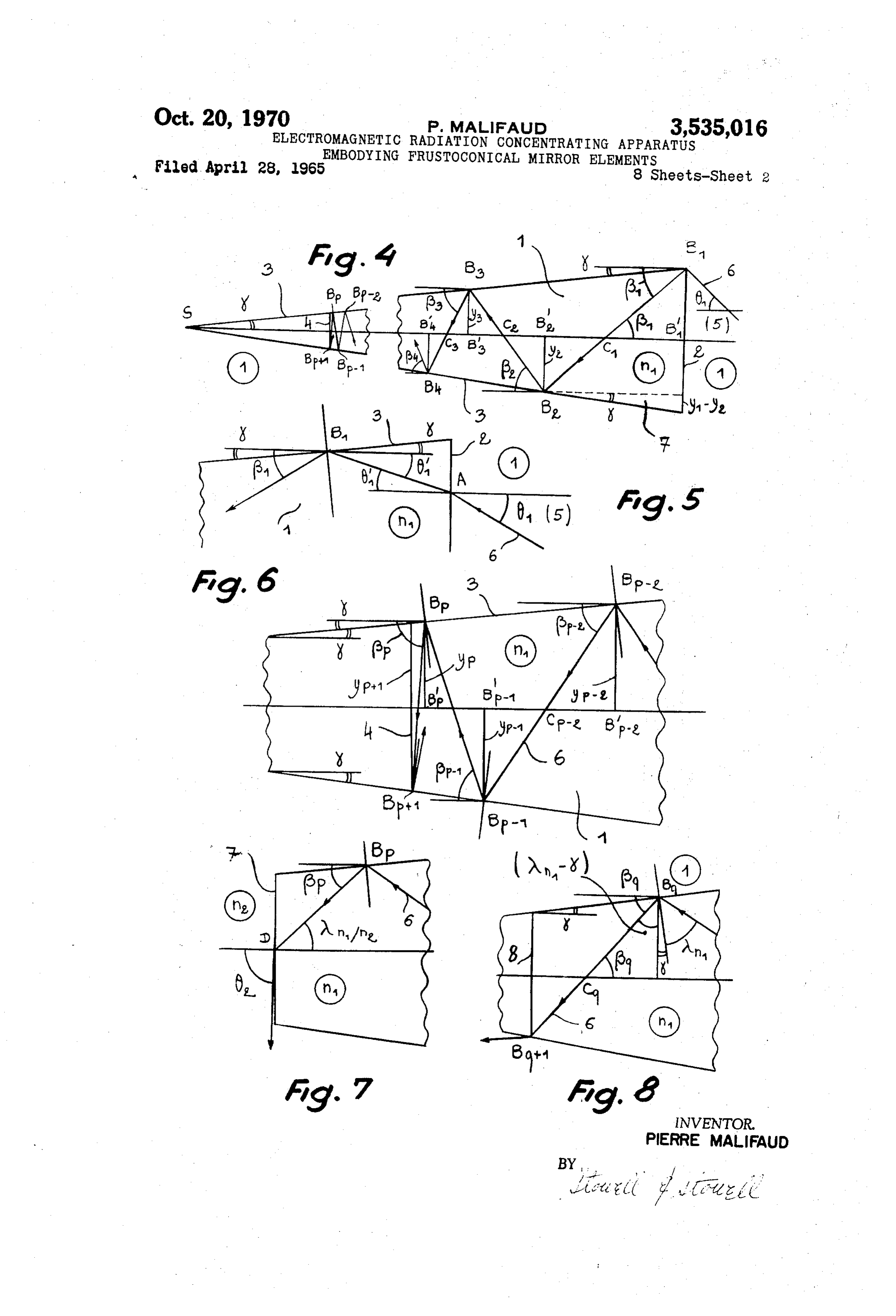
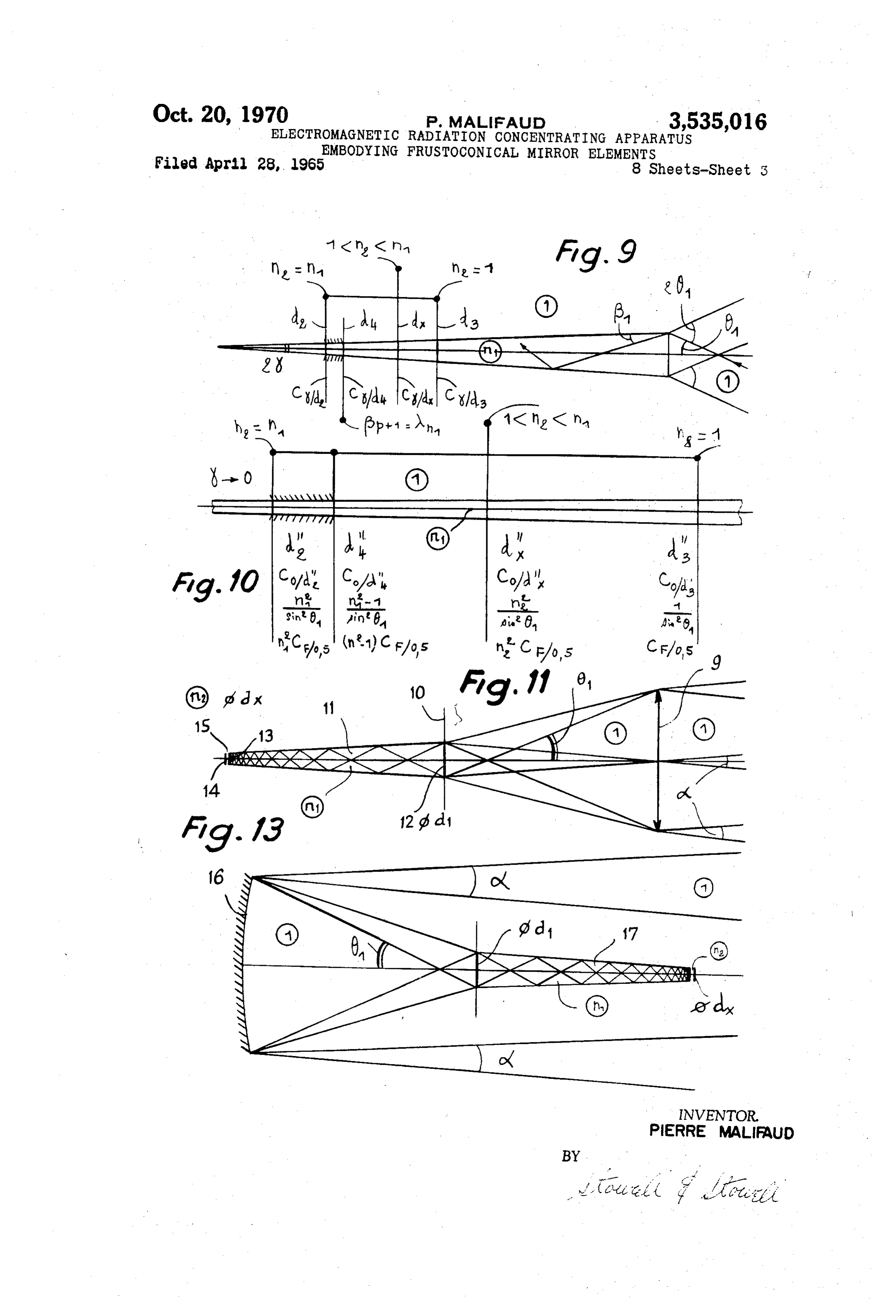
optical elements used in receivers. One sees even now, FIGS. 5 through 10 are fragmentary details illustrating for example, otherwise highly perfected radiation detec aspects of the frustoconical bidiopter of FIG. 4; tors in which the front receiver is a simple "window' FIGS. 11 through 13 are diagrammatic illustrations of transparent to the radiation being detected, such as a the combination of a frontal convergent system with the plate with parallel or lightly curved faces without well bidiopter of FIG. 4;
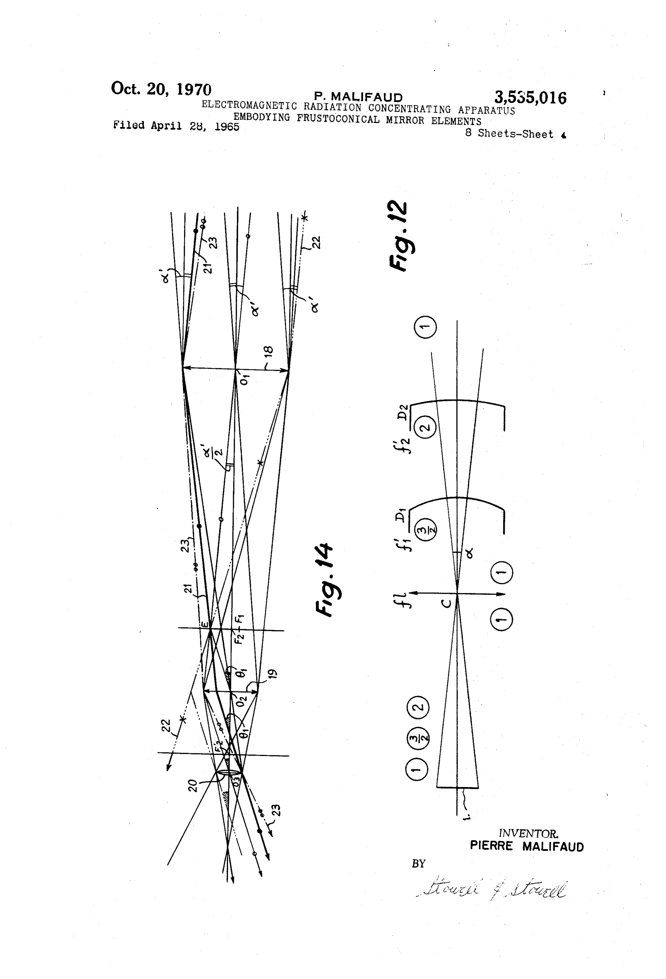
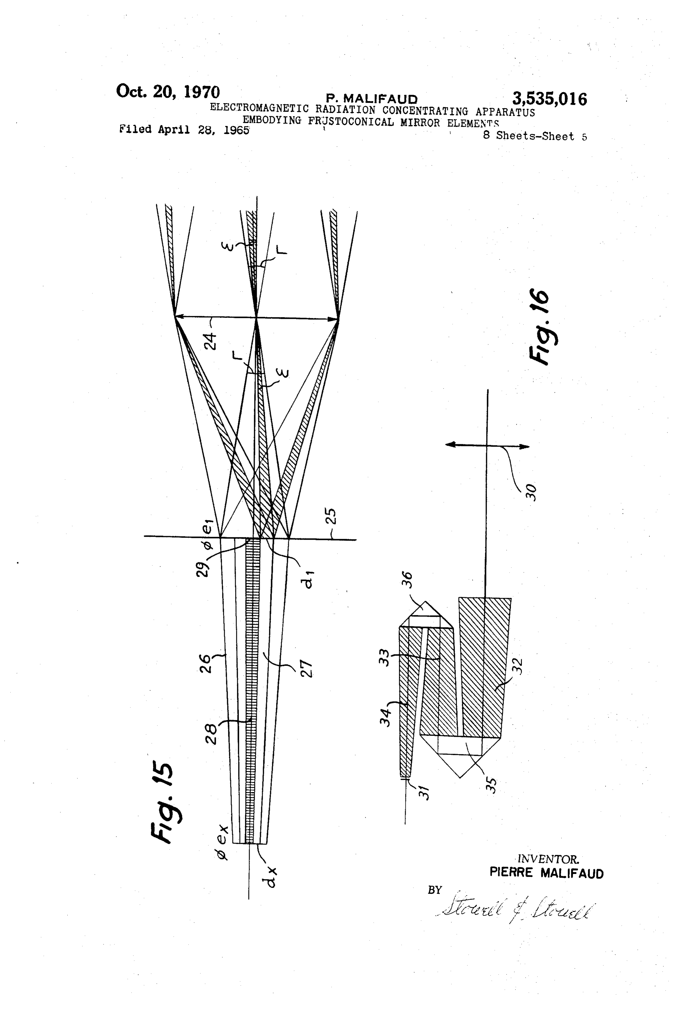
defined optical characteristics. Thus the problem of the FIG. 14 is a diagram of an afocal system; maximum optical concentration of a flux of radiant energy FIG. 15 is a diagram of the combination of an afocal under the given conditions has not been Solved or even frontal system with a frustoconical bidiopter; posed. FIG. 16 is a diagram of a folded bidiopter embodying Nevertheless it is clear that what is of primary im 70 the principles of the invention;
portance for the efficiency of a receiver is the quantity FIG. 17 is a diagram of a thermistor bolometer em of radiation utilized per unit of sensing Surface, that is, bodying the principles of the invention;
Page 10
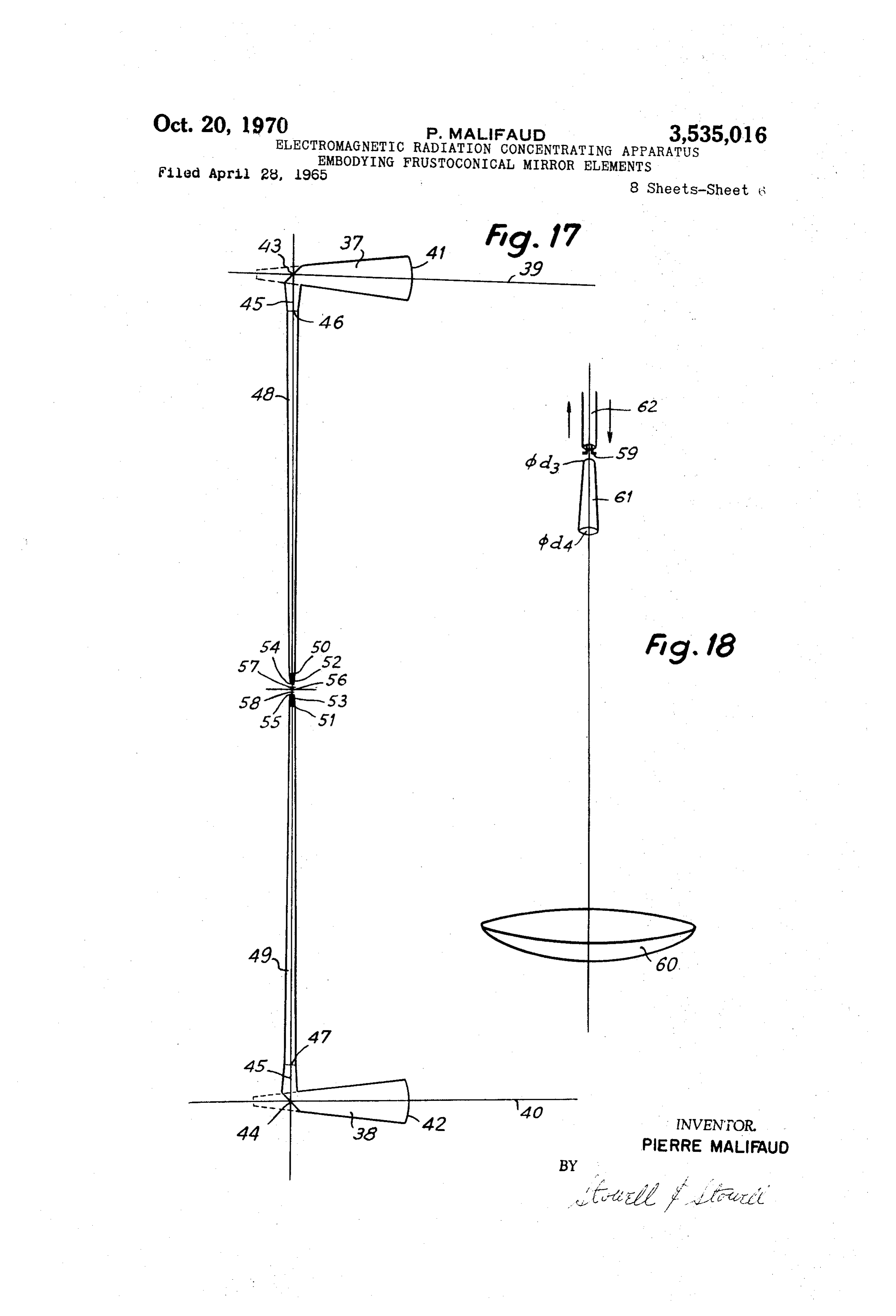
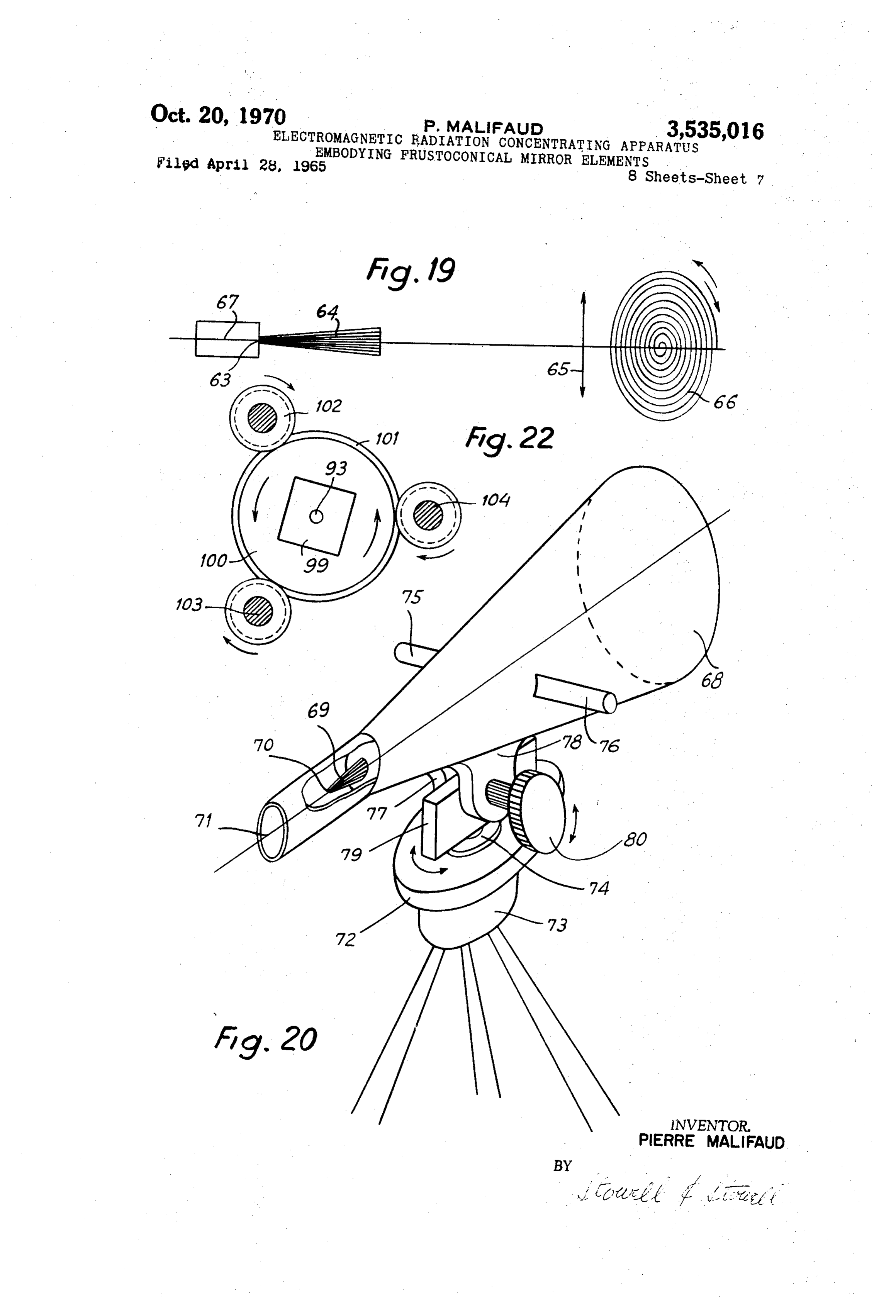
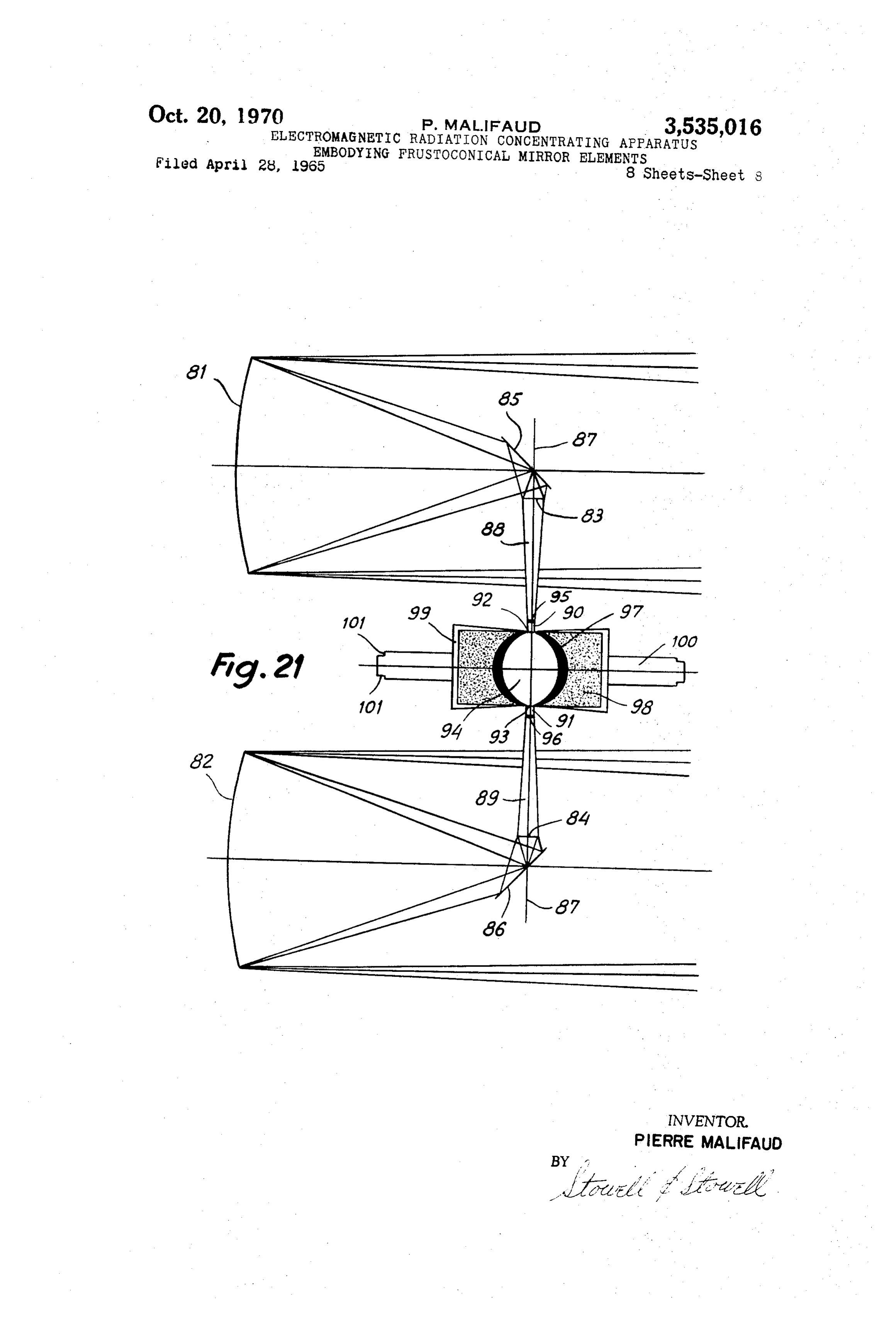
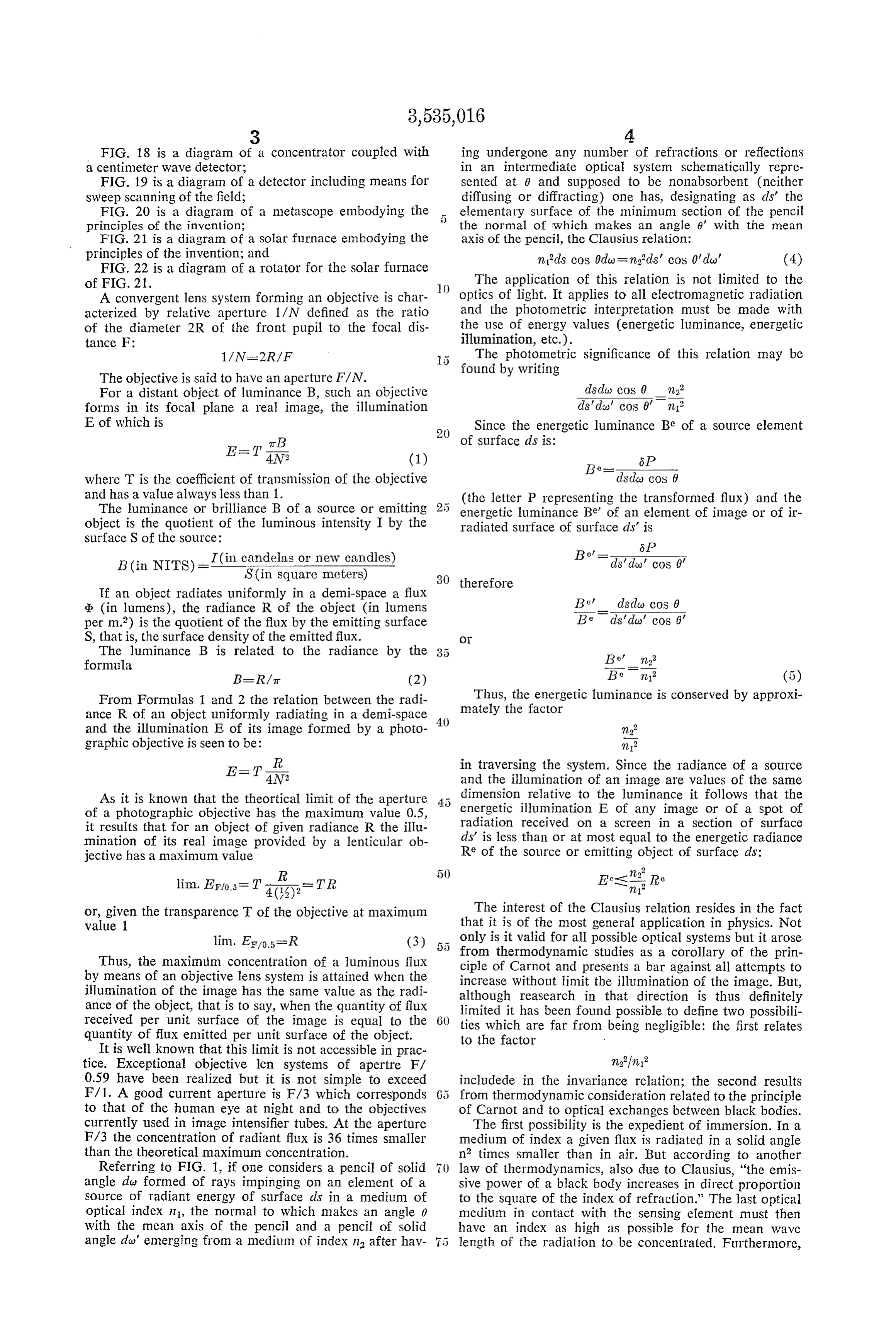
FIG. 18 is a diagram of a concentrator coupled with ing undergone any number of refractions or reflections a centimeter wave detector; in an intermediate optical system schematically repre FIG. 19 is a diagram of a detector including means for sented at 9 and supposed to be nonabsorbent (neither sweep scanning of the field; diffusing or diffracting) one has, designating as als' the FIG. 20 is a diagram of a metascope embodying the 5 elementary surface of the minimum section of the pencil principles of the invention; - the normal of which makes an angle 6' with the mean FIG. 21 is a diagram of a solar furnace embodying the axis of the pencil, the Clausius relation: principles of the invention; and mids cos 0dc = n.ds' cos 0'day' (4) FIG. 22 is a diagram of a rotator for the solar furnace of FIG. 21. The application of this relation is not limited to the A convergent lens system forming an objective is char O optics of light. It applies to all electromagnetic radiation acterized by relative aperture 1/N defined as the ratio and the photometric interpretation must be made with of the diameter 2R of the front pupil to the focal dis the use of energy values (energetic luminance, energetic tance F: illumination, etc.).
1/N-2R/F The photometric significance of this relation may be
The objective is said to have an aperture F/N. found by writing
For a distant object of luminance B, such an objective disda) cos 0 m2 forms in its focal plane a real image, the illumination ds'do' cos 0 m
E of which is Since the energetic luminance Be of a source element
where T is the coefficient of transmission of the objective disda) cos 0 and has a value always less than 1. (the letter P representing the transformed flux) and the The luminance or brilliance B of a source or emitting energetic luminance Be' of an element of image or of ir object is the quotient of the luminous intensity I by the radiated surface of surface dis' is surface S of the source:
B(in NITS)= I (in candelas or new candles)
S(in square meters)
B's fees of 30 therefore
If an object radiates uniformly in a demi-space a flux q (in lumens), the radiance R of the object (in lumens Bedsdo cos 0 per m.?) is the quotient of the flux by the emitting surface Beds' de' cos 0. S, that is, the surface density of the emitted flux. O
The luminance B is related to the radiance by the Bef n formula
B= RAir (2) Be m2 (5) From Formulas 1 and 2 the relation between the radi Thus, the energetic luminance is conserved by approxi ance R of an object uniformly radiating in a demi-space mately the factor and the illumination E of its image formed by a photo 40 n graphic objective is seen to be: n? I in traversing the system. Since the radiance of a source
E=TN, and the illumination of an image are values of the same
As it is known that the theoritical limit of the aperture dimension relative to the luminance it follows that the of a photographic objective has the maximum value 0.5, energetic illumination E of any image or of a spot of it results that for an object of given radiance R the illu radiation received on a screen in a section of Surface mination of its real image provided by a lenticular ob ds' is less than or at most equal to the energetic radiance jective has a maximum value Re of the source or emitting object of Surface ds:
or, given the transparence T of the objective at maximum The interest of the Clausius relation resides in the fact value 1 that it is of the most general application in physics. Not lim. EF/o.5=R only is it valid for all possible optical systems but it arose (3) 5 5 from thermodynamic studies as a corollary of the prin
Thus, the maxinuim concentration of a luminous flux ciple of Carnot and presents a bar against all attempts to by means of an objective lens system is attained when the increase without limit the illumination of the image. But, illumination of the image has the same value as the radi although reasearch in that direction is thus definitely ance of the object, that is to say, when the quantity of flux received per unit surface of the image is equal to the 60 limited ties it has been found possible to define two possibili which are far from being negligible: the first relates quantity of flux emitted per unit surface of the object. to the factor
It is well known that this limit is not accessible in prac tice. Exceptional objective len systems of apertre F/ 0.59 have been realized but it is not simple to exceed includede in the invariance relation; the second results F/1. A good current aperture is F/3 which corresponds 65 from thermodynamic consideration related to the principle to that of the human eye at night and to the objectives of Carnot and to optical exchanges between black bodies. currently used in image intensifier tubes. At the aperture The first possibility is the expedient of immersion. In a F/3 the concentration of radiant flux is 36 times smaller medium of index a given flux is radiated in a solid angle than the theoretical maximum concentration. n times smaller than in air. But according to another Referring to FIG. 1, if one considers a pencil of solid law of thermodynamics, also due to Clausius, "the emis angle day formed of rays impinging on an element of a sive power of a black body increases in direct proportion source of radiant energy of surface ds in a medium of to the square of the index of refraction.” The last optical optical index n1, the normal to which makes an angle 0 medium in contact with the sensing element must then with the mean axis of the pencil and a pencil of solid have an index as high as possible for the mean wave angle dos' emerging from a medium of index n after hav length of the radiation to be concentrated. Furthermore,
Page 11
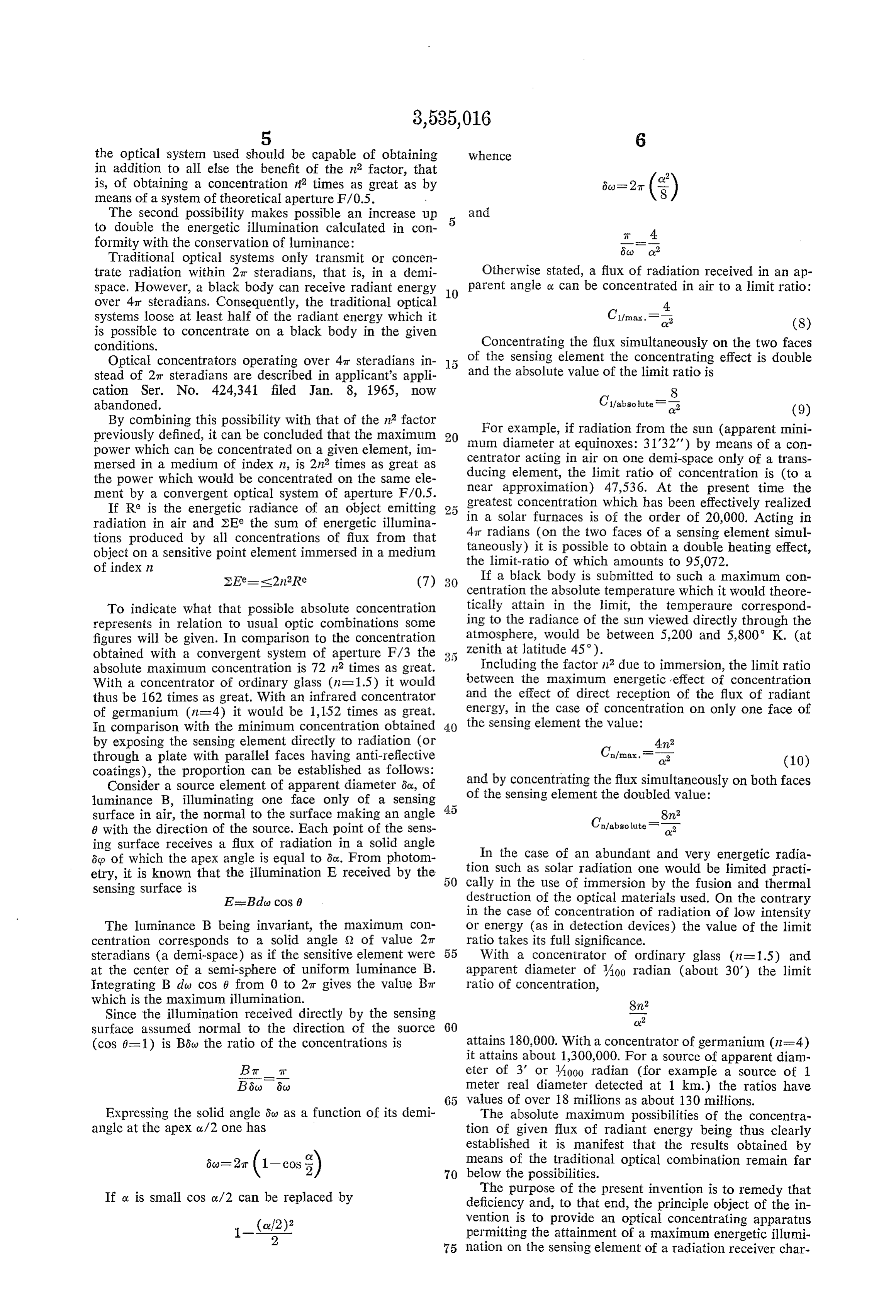
the optical system used should be capable of obtaining whence in addition to all else the benefit of the n2 factor, that is, of obtaining a concentration if times as great as by means of a System of theoretical aperture F/0.5.
The Second possibility makes possible an increase up and to double the energetic illumination calculated in con 5 formity with the conservation of luminance: T-4 Traditional optical systems only transmit or concen 6cs c2 trate radiation within 2T steradians, that is, in a demi Otherwise stated, a flux of radiation received in an ap space. However, a black body can receive radiant energy O parent angle O. can be concentrated in air to a limit ratio:
over 4T steradians. Consequently, the traditional optical 4. systems loose at least half of the radiant energy which it (8) is possible to concentrate on a black body in the given conditions. Concentrating the flux simultaneously on the two faces Optical concentrators operating over 4T steradians in of the Sensing element the concentrating effect is double stead of 2r steradians are described in applicant's appli and the absolute value of the limit ratio is cation Ser. No. 424,341 filed Jan. 8, 1965, now 8 abandoned. C fabsolute absolute cy?
By combining this possibility with that of the in factor (9) For example, if radiation from the Sun (apparent previously defined, it can be concluded that the maximum 20 mum diameter at equinoxes: 31'32') by means of a con mini power which can be concentrated on a given element, im centrator acting in air on one demi-space only of a trans mersed in a medium of index n, is 2n times as great as the power which would be concentrated on the same ele ducing element, the limit ratio of concentration is (to a ment by a convergent optical system of aperture F/0.5. near approximation) 47,536. At the present time the If Re is the energetic radiance of an object emitting 25 greatest concentration which has been effectively realized radiation in air and 2Ee the sum of energetic illumina in a Solar furnaces is of the order of 20,000. Acting in tions produced by all concentrations of flux from that 4t radians (on the two faces of a sensing element simul object on a sensitive point element innmersed in a medium taneously) it is possible to obtain a double heating effect, of index in the limit-ratio of which amounts to 95,072. (7) If a black body is Submitted to such a maximum con centration the absolute temperature which it would theore
To indicate what that possible absolute concentration tically attain in the limit, the temperaure correspond represents in relation to usual optic combinations Some ing to the radiance of the sun viewed directly through the figures will be given. In comparison to the concentration atmosphere, would be between 5,200 and 5,800 K. (at obtained with a convergent system of aperture F/3 the 3 5 Zenith at latitude 45).
absolute maximum concentration is 72 in times as great. Including the factor in due to immersion, the limit ratio With a concentrator of ordinary glass (n=1.5) it would between the maximum energetic effect of concentration thus be 162 times as great. With an infrared concentrator and the effect of direct reception of the flux of radiant of germanium (n=4) it would be 1,152 times as great. energy, in the case of concentration on only one face of In comparison with the minimum concentration obtained 40 the Sensing element the value:
by exposing the sensing element directly to radiation (or 42 through a plate with parallel faces having anti-reflective coatings), the proportion can be established as follows:
Consider a source element of apparent diameter &c., of and by concentrating the flux simultaneously on both faces luminance B, illuminating one face only of a sensing of the sensing element the doubled value: surface in air, the normal to the surface making an angle 82 6 with the direction of the source. Each point of the Sens Ca/abso lutes
ing surface receives a flux of radiation in a solid angle In the case of an abundant and very energetic radia 6p of which the apex angle is equal to 6oz. From photom etry, it is known that the illumination E received by the tion Such as Solar radiation one would be limited practi sensing surface is cally in the use of immersion by the fusion and thermal EastEdo cos 6 destruction of the optical materials used. On the contrary in the case of concentration of radiation of low intensity
The luminance B being invariant, the maximum con or energy (as in detection devices) the value of the limit centration corresponds to a solid angle S2 of value 27t ratio takes its full significance. steradians (a demi-space) as if the sensitive element Were 55 With a concentrator of ordinary glass (n=1.5) and at the center of a semi-sphere of uniform luminance B. apparent diameter of A00 radian (about 30') the limit Integrating B do cos 0 from 0 to 27t gives the value Bt ratio of concentration, which is the maximum illumination.
Since the illumination received directly by the sensing 8ncy? surface assumed normal to the direction of the Suorce 60 (cos 0=1) is Bóo the ratio of the concentrations is attains 180,000. With a concentrator of germanium (n=4) it attains about 1,300,000. For a source of apparent diam
Bat it eter of 3' or 4000 radian (for example a source of 1 meter real diameter detected at 1 km.) the ratios have values of over 18 millions as about 130 millions.
Expressing the solid angle Scy as a function of its demi The absolute maximum possibilities of the concentra angle at the apex ox/2 one has tion of given flux of radiant energy being thus clearly established it is manifest that the results obtained by 6a)=2ar (1-cos ) means of the traditional optical combination remain far 70 below the possibilities.
If ox is small cos or /2 can be replaced by The purpose of the present invention is to remedy that deficiency and, to that end, the principle object of the in (af2)? vention is to provide an optical concentrating apparatus 1-s; permitting the attainment of a maximum energetic illumi 75 nation on the sensing element of a radiation receiver char
Page 12
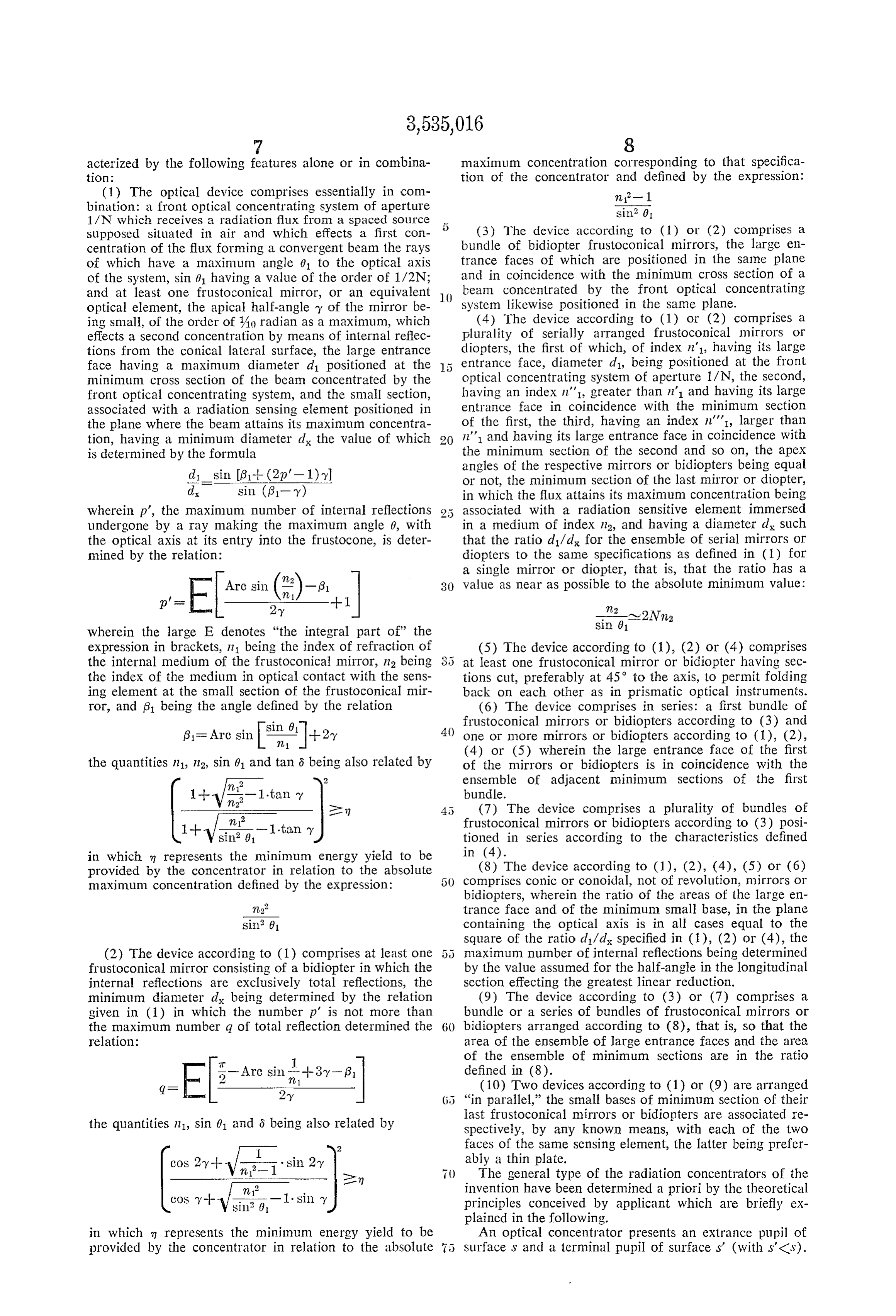
acterized by the following features alone or in combina maximum concentration corresponding to that Specifica tion: tion of the concentrator and defined by the expression: (1) The optical device comprises essentially in com in - 1 bination: a front optical concentrating system of aperture sin 01. 1/N which receives a radiation flux from a spaced source supposed situated in air and which effects a first con (3) The device according to (1) or (2) comprises a centration of the flux forming a convergent beam the rays bundle of bidiopter frustoconical mirrors, the large en of which have a maximum angle 0 to the optical axis trance faces of which are positioned in the Same plane of the system, sin () having a value of the order of 1/2N; and in coincidence with the minimum croSS Section of a and at least one frustoconical mirror, or an equivalent O beam concentrated by the front optical concentrating optical element, the apical half-angle y of the mirror be system likewise positioned in the same plane. ing small, of the order of Ao radian as a maximum, which (4) The device according to (1) or (2) comprises a effects a second concentration by means of internal reflec plurality of serially arranged frustioconical mirrors or tions from the conical lateral surface, the large entrance diopters, the first of which, of index n1, having its large face having a maximum diameter d positioned at the entrance face, diameter d, being positioned at the front minimum cross section of the beam concentrated by the optical concentrating system of aperture 1/N, the Second, front optical concentrating system, and the Small Section, having an index n', greater than n' and having its large associated with a radiation sensing element positioned in entrance face in coincidence with the minimum Section the plane where the beam attains its maximum concentra of the first, the third, having an index n'1, larger than tion, having a minimum diameter d the value of which n' and having its large entrance face in coincidence with is determined by the formula the minimum section of the second and so on, the apex angles of the respective mirrors or bidiopters being equal disin (81-- (2p-1) or not, the minimum section of the last mirror or diopter, d sin (g 1- y) in which the flux attains its maximum concentration being wherein p', the maximum number of internal reflections 2 5 associated with a radiation sensitive element immersed undergone by a ray making the maximum angle 0, with in a medium of index 12, and having a diameter dx Such the optical axis at its entry into the frustOcone, is deter that the ratio d/d for the ensemble of Serial mirrors Or mined by the relation: diopters to the same specifications as defined in (1) for a single mirror or diopter, that is, that the ratio has a
Arc sin () 30 value as near as possible to the absolute minimum value:
-E 2-y --1 222
wherein the large E denotes "the integral part of the sin 01 expression in brackets, n1 being the index of refraction of (5) The device according to (1), (2) or (4) comprises the internal medium of the frustioconical mirror, n2 being 8 5 at least one frustoconical mirror or bidiopter having Sec the index of the medium in optical contact with the Sens tions cut, preferably at 45° to the axis, to permit folding ing element at the small section of the frustoconical mir back on each other as in prismatic optical instruments. ror, and 3 being the angle defined by the relation (6) The device comprises in series: a first bundle of sin 61 frustoconical mirrors or bidiopters according to (3) and 51st Arc sin 22. +2, one or more mirrors or bidiopters according to (1), (2), (4) or (5) wherein the large entrance face of the first the quantities in 1, 112, sin 01 and tan 8 being also related by of the mirrors or bidiopters is in coincidence with the
- ensemble of adjacent minimum sections of the first
(7) The device comprises a plurality of bundles of frustoconical mirrors or bidiopters according to (3) posi 1- V sin 61 ...tain y tioned in series according to the characteristics defined in which m represents the minimum energy yield to be in (4).
provided by the concentrator in relation to the absolute (8) The device according to (1), (2), (4), (5) or (6) maximum concentration defined by the expression: comprises conic or conoidal, not of revolution, mirrors or bidiopters, wherein the ratio of the areas of the large en n trance face and of the minimum small base, in the plane sin: 61 containing the optical axis is in all cases equal to the square of the ratio d/d specified in (1), (2) or (4), the (2) The device according to (1) comprises at least one 5 naximum number of internal reflections being determined frustoconical mirror consisting of a bidiopter in which the by the value assumed for the half-angle in the longitudinal internal reflections are exclusively total reflections, the section effecting the greatest linear reduction. minimum diameter d being determined by the relation (9) The device according to (3) or (7) comprises a given in (1) in which the number p' is not more than bundle or a series of bundles of frustoconical mirrors or the maximum number q of total reflection determined the 60 bidiopters arranged according to (8), that is, so that the relation: area of the ensemble of large entrance faces and the area. of the ensemble of minimum sections are in the ratio f– Arn six -l 2
gR E (10) Two devices according to (1) or (9) are arranged “in parallel,' the small bases of minimum section of their the quantities in1, sin 01 and 6 being also related by last frustioconical mirrors or bidiopters are associated re spectively, by any known means, with each of the two | I 2 faces of the same sensing element, the latter being prefer cos 2 y -- 2- - sin 2 ably a thin plate.
en () The general type of the radiation concentrators of the 1. invention have been determined a priori by the theoretical cos y -- - -sil 0 -l sin y principles conceived by applicant which are briefly ex plained in the following.
in which in represents the minimum energy yield to be An optical concentrator presents an extrance pupil of provided by the concentrator in relation to the absolute Surface S and a terminal pupil of Surfaces' (with s'<s).
Page 13
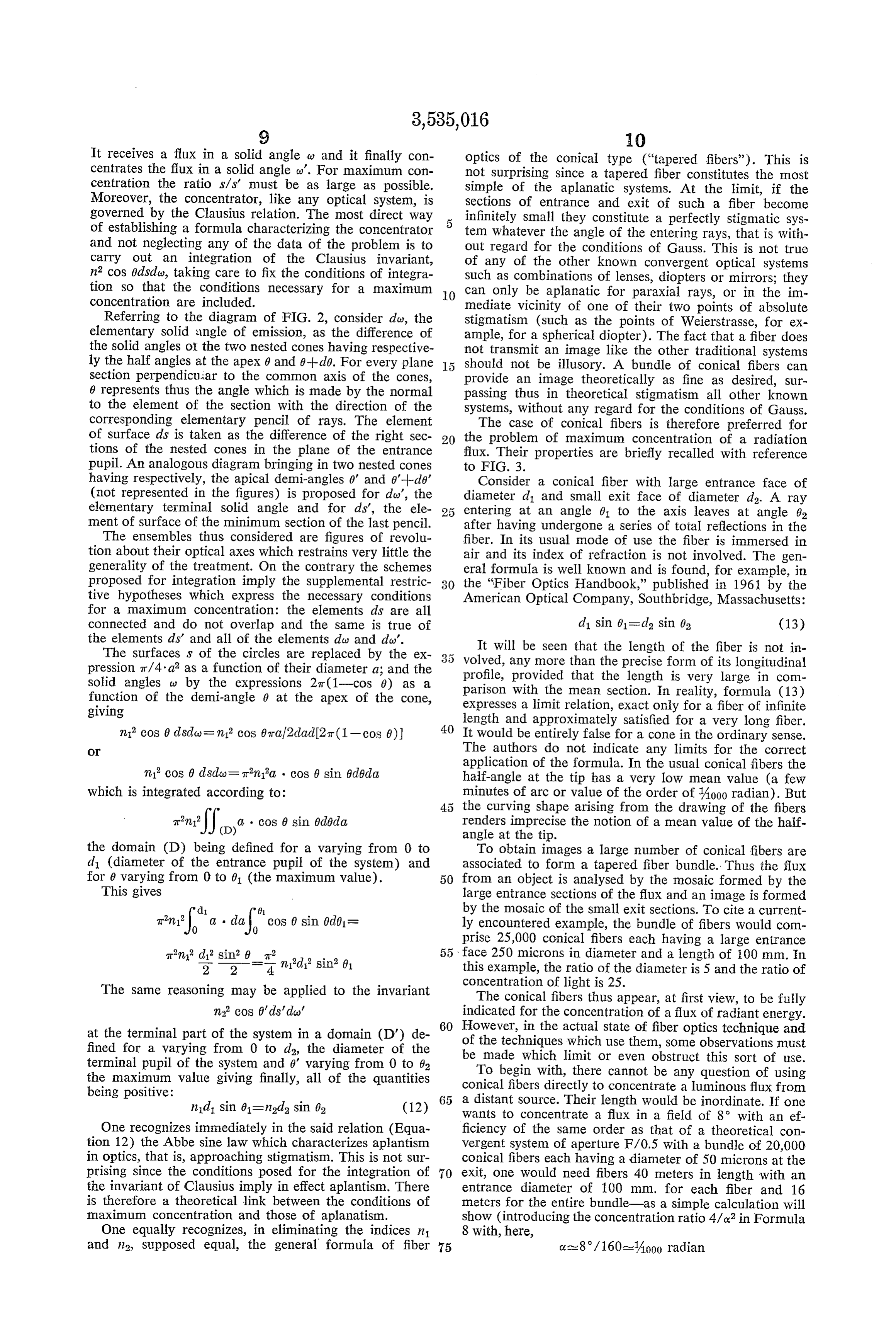
It receives a flux in a solid angle w and it finally con optics of the conical type ("tapered fibers'). This is centrates the flux in a solid angle w'. For maximum con not surprising since a tapered fiber constitutes the most centration the ratio s/s' must be as large as possible. simple of the aplanatic systems. At the limit, if the Moreover, the concentrator, like any optical system, is Sections of entrance and exit of such a fiber become governed by the Clausius relation. The most direct way 5 infinitely small they constitute a perfectly stigmatic sys of establishing a formula characterizing the concentrator tem whatever the angle of the entering rays, that is with and not neglecting any of the data of the problem is to out regard for the conditions of Gauss. This is not true carry out an integration of the Clausius invariant, of any of the other known convergent optical systems n2 cos 0dsdw, taking care to fix the conditions of integra Such as combinations of lenses, diopters or mirrors; they tion so that the conditions necessary for a maximum 0 can only be aplanatic for paraxial rays, or in the im concentration are included. mediate vicinity of one of their two points of absolute Referring to the diagram of FIG. 2, consider dw, the stigmatism (such as the points of Weierstrasse, for ex elementary solid angle of emission, as the difference of ample, for a spherical diopter). The fact that a fiber does the solid angles of the two nested cones having respective not transmit an image like the other traditional systems ly the half angles at the apex 0 and 0--do. For every plane should not be illusory. A bundle of conical fibers can section perpendicular to the common axis of the cones, provide an image theoretically as fine as desired, Sur 6 represents thus the angle which is made by the normal passing thus in theoretical stigmatism all other known to the element of the section with the direction of the systems, without any regard for the conditions of Gauss. corresponding elementary pencil of rays. The element The case of conical fibers is therefore preferred for of surface ds is taken as the difference of the right sec 20 the problem of maximum concentration of a radiation tions of the nested cones in the plane of the entrance flux. Their properties are briefly recalled with reference pupil. An analogous diagram bringing in two nested cones to FIG. 3.
having respectively, the apical demi-angles 0' and 0'--d6' Consider a conical fiber with large entrance face of (not represented in the figures) is proposed for day', the diameter d1 and small exit face of diameter d2. A ray elementary terminal solid angle and for ds', the ele 25 entering at an angle 01 to the axis leaves at angle 62 ment of surface of the minimum section of the last pencil. after having undergone a series of total reflections in the The ensembles thus considered are figures of revolu fiber. In its usual mode of use the fiber is immersed in tion about their optical axes which restrains very little the air and its index of refraction is not involved. The gen generality of the treatment. On the contrary the Schemes eral formula is well known and is found, for example, in proposed for integration imply the supplemental restric 30 the “Fiber Optics Handbook,” published in 1961 by the tive hypotheses which express the necessary conditions American Optical Company, Southbridge, Massachusetts: for a maximum concentration: the elements ds are all connected and do not overlap and the same is true of d sin 61= d2 sin 62 (13) the elements ds' and all of the elements day and day'. It will be seen that the length of the fiber is not in The surfaces is of the circles are replaced by the ex volved, any more than the precise form of its longitudinal pression tr/4'a? as a function of their diameter a; and the profile, provided that the length is very large in com solid angles w by the expressions 2t(1-cos 0) as a parison with the mean section. In reality, formula (13) function of the demi-angle 0 at the apex of the cone, expresses a limit relation, exact only for a fiber of infinite giving length and approximately satisfied for a very long fiber.
It would be entirely false for a cone in the ordinary sense.
O The authors do not indicate any limits for the correct application of the formula. In the usual conical fibers the in cos 0 dsdo= Tinia. . cos 6 sin Gd5da half-angle at the tip has a very low mean value (a few which is integrated according to: minutes of arc or value of the order of Aooo radian). But the curving shape arising from the drawing of the fibers an (D) a cos 0 sin 0doda renders imprecise the notion of a mean value of the half angle at the tip.
the domain (D) being defined for a varying from 0 to To obtain images a large number of conical fibers are di (diameter of the entrance pupil of the System) and associated to form a tapered fiber bundle. Thus the flux for 0 varying from 0 to 0 (the maximum value). from an object is analysed by the mosaic formed by the This gives large entrance sections of the flux and an image is formed di 0. by the mosaic of the small exit sections. To cite a current an: , C, a de?, cos 0 sin Gd81= ly encountered example, the bundle of fibers would com prise 25,000 conical fibers each having a large entrance
Trn d? sin2 6 r2 face 250 microns in diameter and a length of 100 mm. In 2 2 4 ind sin 01. this example, the ratio of the diameter is 5 and the ratio of The same reasoning may be applied to the invariant concentration of light is 25.
The conical fibers thus appear, at first view, to be fully in cos 0'ds'do' indicated for the concentration of a flux of radiant energy. at the terminal part of the system in a domain (D) de 60 of However, in the actual state of fiber optics technique and fined for a varying from 0 to d2, the diameter of the the techniques which use them, some observations must terminal pupil of the system and 0' varying from 0 to 62 be made which limit or even obstruct this sort of use. the maximum value giving finally, all of the quantities To begin with, there cannot be any question of using being positive: conical fibers directly to concentrate a luminous flux from n1d sin 61=nad2 sin 62 (12) a distant source. Their length would be inordinate. If one wants to concentrate a flux in a field of 8 with an ef
One recognizes immediately in the said relation (Equa ficiency of the same order as that of a theoretical con tion 12) the Abbe sine law which characterizes aplantism vergent system of aperture F/0.5 with a bundle of 20,000 in optics, that is, approaching stigmatism. This is not Sur conical fibers each having a diameter of 50 microns at the prising since the conditions posed for the integration of 70 exit, one would need fibers 40 meters in length with an the invariant of Clausius imply in effect aplantism. There entrance diameter of 100 mm. for each fiber and 16 is therefore a theoretical link between the conditions of meters for the entire bundle-as a simple calculation will maximum concentration and those of aplanatism. show (introducing the concentration ratio 4/or in Formula One equally recognizes, in eliminating the indices n1 8 with, here, and n supposed equal, the general formula of fiber 75 oxa- 8/160-A000 radian
Page 14
for each fiber). If one associates the conical fibers with confusing different problems, the first part of the discus a convergent optical system to reduce their length, one sion will consider only the progression of the rays in would be on the way to a more acceptable solution. Never the interior of the cone, eliminating consideration of con theless an empirical association would not furnish the best ditions of total reflection which will be considered sub combinations assuring maximum concentration. Many 5 Sequently.
factors come into play, notably, simplicity and cost of It is evident that in a cone, any ray entering a right producing practical systems. The problem will be treated Section (and not passing through the apex, a very partic hereinafter in a complete manner and the Solutions ular case) will progress by a certain number of reflections utilizing conical fibers will be proposed and constitute the from the lateral surface of the cone up to a certain limit particular application of the invention. () at which the ray reverses upon itself and leaves the cone Further, the fact n, authorized by the Clausius relation by the Sanne Section through which it entered. It can easily and present in the formula which results from its integra be shown that the ray progresses the less far in the cone, tion, is absent from the general formula of conical fibers. the nearer it is to the circumference of the right section These are generally used in air. The problem of in and the greater its inclination to the optical axis. For a mersing the sensing elements in the fibers and its diverse received pencil 5 (FIG. 4) the less favored rays are those impliciaions is to be studied and will be returned to as Such as 6, having a maximum inclination 0 to the axis a particular case of application of the invention. and entering near the edge of the large face 2. The course Finally, the technique and the applications of fiber of ray 6 is calculated with assurance that, if it attains as optics are ancillary to the technology of drawn glass. Ac certain minimum right section, all other received rays tually, fibers have been conceived essentially in connec will also attain it.
tion with visible light and, in a strict sense, with the near Referring to FIG. 5 which shows in detail on a very infrared. But in these domains more notable materials, large Scale a ray 6 entering large face 2 at point. A near such as germanium for example, cannot be drawn into its circular edge and being refracted inclination to the fibers like glass. The present conception of conical fibers axis having a value 01' such that in sin 0,'—sin 0. is here again not adapted for utilization as a concentrator The refracted ray strikes the side of the cone for the of radiation. first time at 31. After reflection (total) at this surface its One must conclude from these remarks that it is neces new inclination to the axis is 31. This angle will be im sary to pursue the problem further and to generalize the portant in the calculations and its value is easily estab conception of a total reflection concentrator, which has lished. On FIG. 5, 01'-- y=f31-y (by reflection) whence been retained, according to the integration of the Clausius 30 f31-61'--2y and since 01'=Arc sin (sin 01/n) (by refrac relation, as being the most simple and the most direct, tion), and of which the conical glass fibers represent only a par ticular example. (31= Arc sin l22.2+2, (14) Such a concentrator can be defined in general terms as a frustoconical diopter, that is, a truncated cone of re The inclination of the ray to the optical axis is thus fractive material, having a large flux receiving right Sec augmented by 2-y upon reflection from the surface of the tion, a minimum right section where the flux attains its cone. It is the same at each reflection and this is the greatest concentration, and a lateral conic Surface whereby fundamental phenomenon for the progression of the ray the radiation is concentrated by internal reflections. In its 40 in the conic diopter.
more general aspect the internal reflections do not have Returning to FIG. 4, the ray 6 is reflected at succes to be total reflections, but may be reflections from a lateral sive points B1, B2, B3 . . . on the surface of the cone mirror surface, such as a metallic coating. In a further up to a point B where, for the last time, it is reflected general aspect, the concentrator may be a conical mirror, toward the apex of the cone. It finally strikes the lateral the index of the interior medium having the value 1, in Surface at point B1 and is reflected backwards, as de which case it is a simple mirror, or a value greater than tailed in FIG. 6.
1, in which case it is a bidiopter, and the term "frusto The right section through B1 is then the minimum conical mirror' is used herein to include mirrors in the Section of the cone attained by ray 6 and the value d of more linited sense and bidiopters, according to whether its diameter is now to be determined. All this is with the index of the interior medium is 1 or greater than 1. reservation of the conditions for total reflection to be The mirror or the bidiopter may have an internal Surface considered subsequently.
which is longitudinally arched, having Substantially the Designate by y, the radius of the large receiving face same optical effect as a conical surface, as is the case with 2, by y2 the radius of the right section passing through drawn glass fibers. The lateral surfaces need not be true B2 and so on y's, y4 . . . to y the radius of the right surfaces of revolution; the right sections being, for ex Section through B and y1 the radius of the minimum ample, elliptical, or the lateral surface may be "conoidal' 5 5 Section through B1. Designate by B1, B2, Ba' . . . B", and transform a flux of circular section into one concen B', B-1' the projections on the optic axis of points trated into a rectilinear section. Only the bidiopters which B1, B2, B3 . . . Bp. Bp-1, respectively; by x1, x2, x3 . . . are frustocones "of revolution' will be considered in de Xp the distances B1, B2, B', Ba', B3" B4' . . . B. B."; tail and will serve as models for all the others, these and by C1, C2, C2 . . . C the intersections with the axis being the form of frustoconical concentrators most fre 60 of the segments B1, B2, B2B3, B3B4 . . . BB-1 respec quently used. tively.
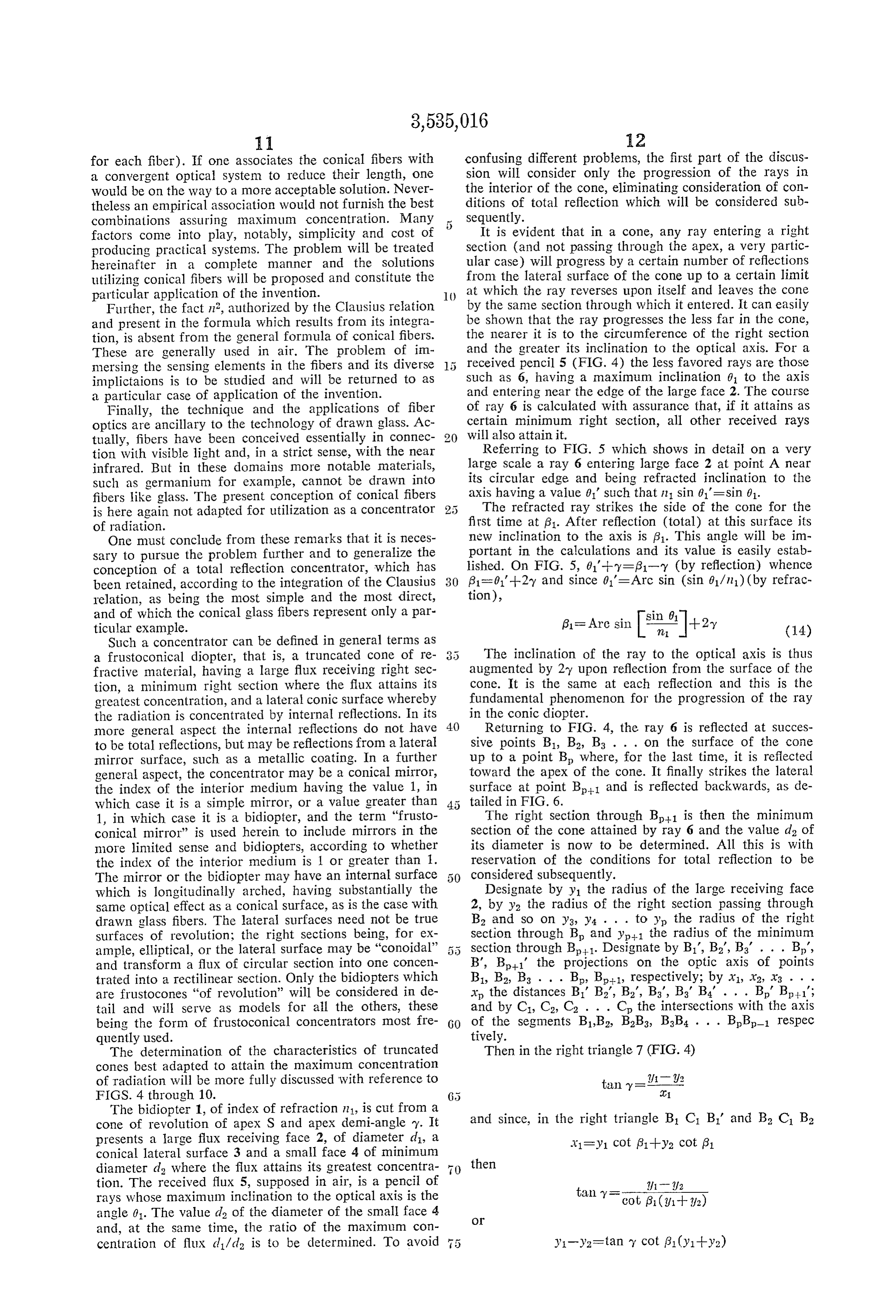
The determination of the characteristics of truncated Then in the right triangle 7 (FIG. 4) cones best adapted to attain the maximum concentration of radiation will be more fully discussed with reference to tan y = 2/1 -1 12 FIGS. 4 through 10.
The bidiopter 1, of index of refraction n1, is cut from a cone of revolution of apex S and apex demi-angle ?y. It and since, in the right triangle B, C, B1 and B C, B2 presents a large flux receiving face 2, of diameter d, a A1=y1 Cot (31-Hy2 cot (31 conical lateral surface 3 and a small face 4 of minimum diameter d where the flux attains its greatest concentra then tion. The received flux 5, supposed in air, is a pencil of tan y = - -2/1 -- 212 rays whose maximum inclination to the optical axis is the angle 01. The value d of the diameter of the small face 4
and, at the same time, the ratio of the maximum con centration of flux d/d is to be determined. To avoid y1-y2=tan Y cot (31 (y1-y2)
Page 15
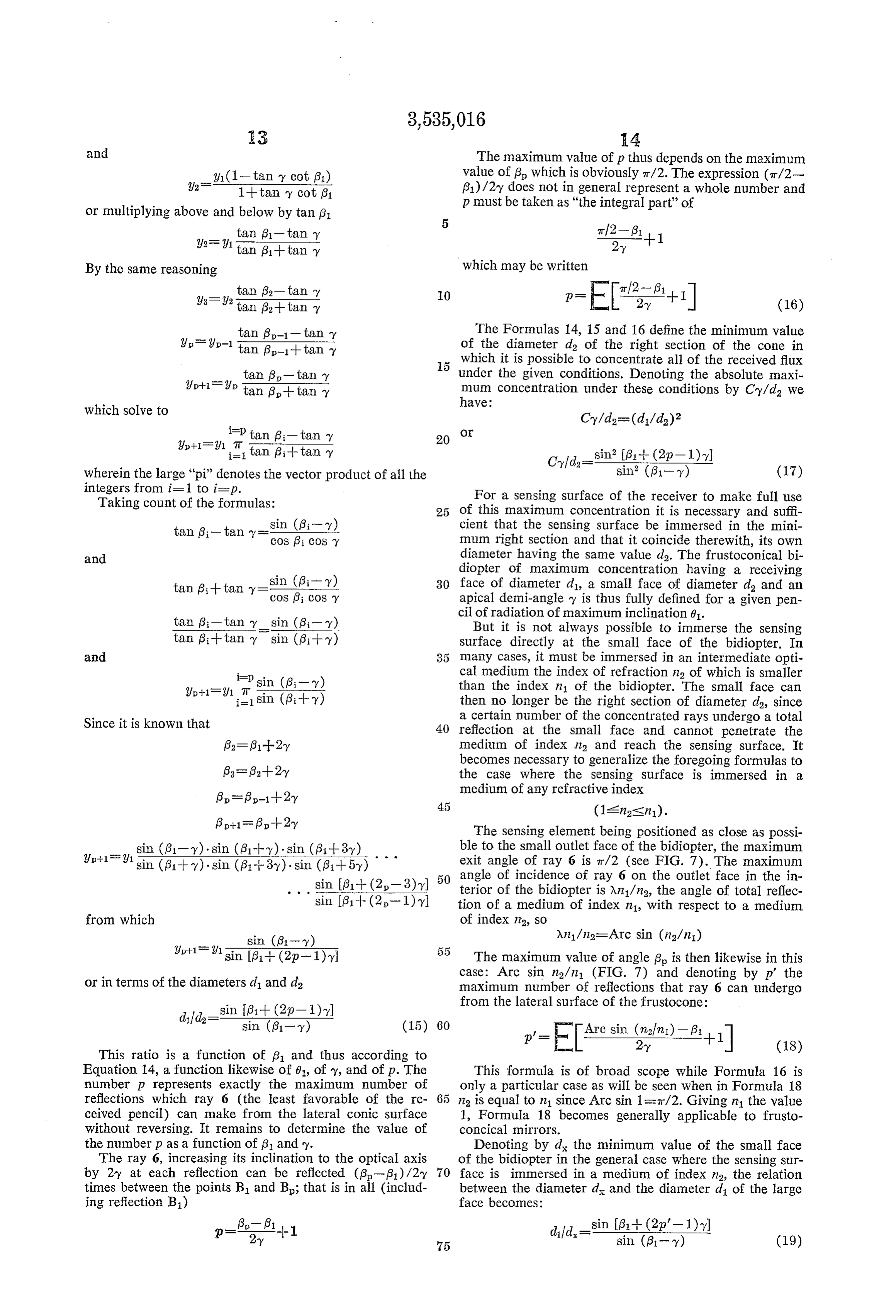
and The maximum value of p thus depends on the maximum value of g which is obviously it?2. The expression (T/2-
1--tany cot 8. g1)/2y does not in general represent a whole number and p must be taken as "the integral part” of or multiplying above and below by tan (31 tan (31-tan Y T/2-6, --1 92-91 a 61--tan ?y 2-y
By the same reasoning which may be written tan 62-tan y 989tan 3.--tan O p-El P+1 (16) tan (3-1-tan y The Formulas 14, 15 and 16 define the minimum value Up-9p–1 a (3-1--tan Y of the diameter de of the right section of the cone in which it is possible to concentrate all of the received flux - tan 6-tan y under the given conditions. Denoting the absolute maxi p--if p tan (3- tan 1. mum concentration under these conditions by Cy/d we have:
which solve to
2+1=2f1 i=7t tan (8i-tan y sin 61 -- (2p-1). wherein the large "pi" denotes the vector product of all the integers from i=1 to i=p.
Taking count of the formulas: For a sensing surface of the receiver to make full use 25 of this maximum concentration it is necessary and suffi ; -t. sin (6;- y) cient that the sensing surface be immersed in the mini tan (3i-tan y ccos (3i cos Y mum right section and that it coincide therewith, its own and diameter having the same value d. The frustoconical bi diopter of maximum concentration having a receiving sin (8-y) 30 face of diameter d, a small face of diameter d, and an tan (3-tan cos g; cosy apical demi-angle y is thus fully defined for a given pen cil of radiation of maximum inclination 01.
tan Bi-tan Ysin (8i Y). But it is not always possible to immerse the sensing tan (3--tan y sin (6;-- y) surface directly at the small face of the bidiopter. In and many cases, it must be immersed in an intermediate opti Psin (6, -y) cal medium the index of refraction na of which is smaller than the index n1 of the bidiopter. The small face can l/p--1 J, T, sin (gi -- y) then no longer be the right section of diameter d, since Since it is known that a certain number of the concentrated rays undergo a total 40 reflection at the small face and cannot penetrate the {32– 31-H2-y medium of index n2 and reach the sensing surface. It becomes necessary to generalize the foregoing formulas to 6= 3-2-y the case where the sensing surface is immersed in a 6 = 5-1-2y medium of any refractive index
The sensing element being positioned as close as possi sin (81-y) sin (81-- y) sin (81-3y) - ble to the small outlet face of the bidiopter, the maximum sin (6- ). sin (8-3).sin (ga--5) exit angle of ray 6 is t/2 (see FIG. 7). The maximum 50 angle of incidence of ray 6 on the outlet face in the in
sin g1-1-(2-1) y terior of the bidiopter is An/n3, the angle of total reflec tion of a medium of index n1, with respect to a medium from which of index n2, So 2-12 sin (61- y) An1/na-Arc sin (n2/n)
The maximum value of angle 6 is then likewise in this case: Arc sin na/n (FIG. 7) and denoting by p' the or in terms of the diameters d and d2 maximum number of reflections that ray 6 can undergo from the lateral surface of the frustocone:
This ratio is a function of 31 and thus according to
p'-E AArc single)-P+1
Equation 14, a function likewise of 61, of y, and of p. The This formula is of broad scope while Formula 16 is number p represents exactly the maximum number of only a particular case as will be seen when in Formula 18 reflections which ray 6 (the least favorable of the re 65 n2 is equal to n1 since Arc sin 1=7t/2. Giving in the value ceived pencil) can make from the lateral conic surface 1, Formula 18 becomes generally applicable to frusto without reversing. It remains to determine the value of concical mirrors.
the number p as a function of 61 and y. Denoting by d the minimum value of the small face The ray 6, increasing its inclination to the optical axis of the bidiopter in the general case where the sensing sur by 2-y at each reflection can be reflected (g-?31)/2-y 70 face is immersed in a medium of index n2, the relation times between the points B1 and B; that is in all (includ between the diameter d and the diameter d of the large ing reflection B1) face becomes:
75 sin (81- y) (19)
Page 16
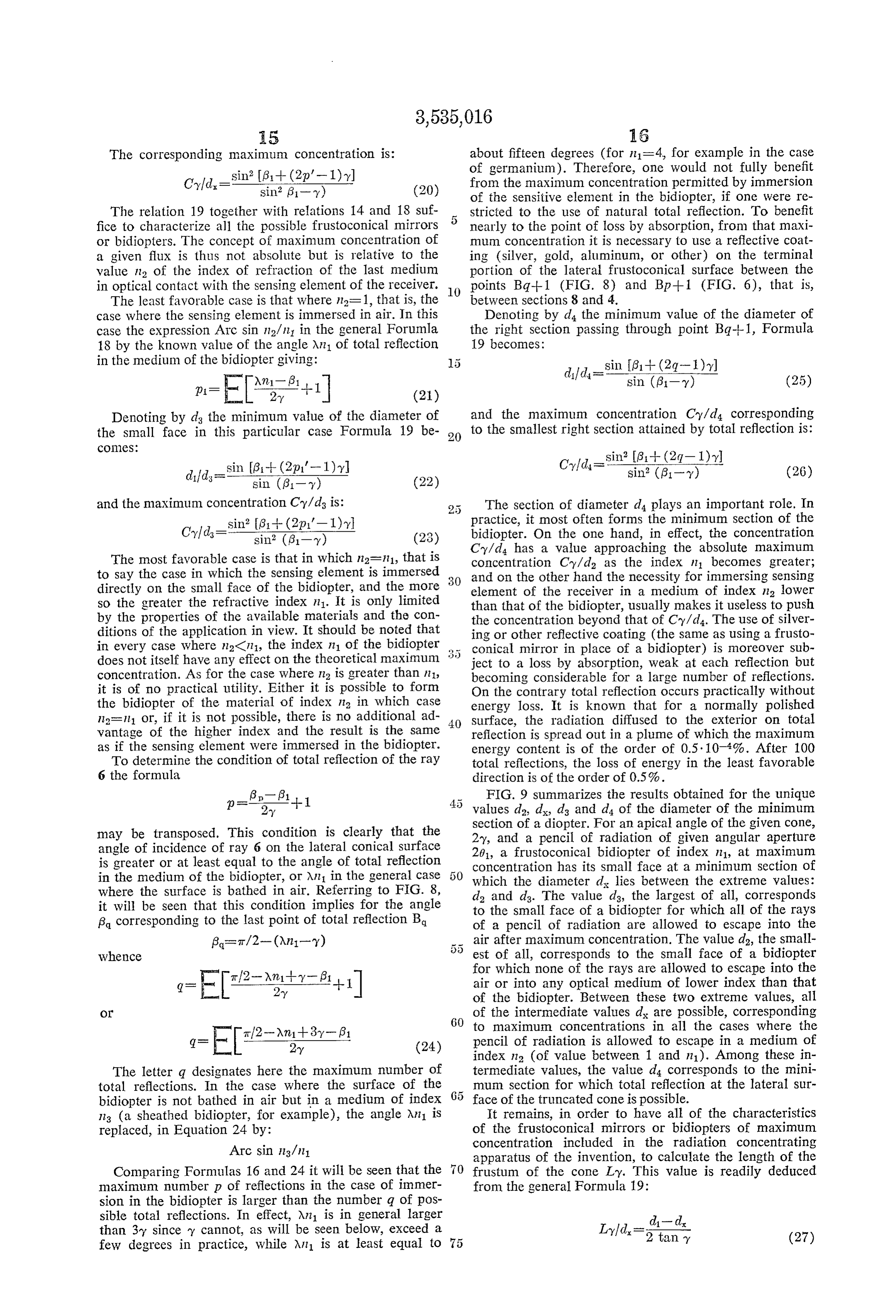
The corresponding maximum concentration is: about fifteen degrees (for n=4, for example in the case sin? If3 + (2p'-1) y) of germanium). Therefore, one would not fully benefit Cld,-in it. (20) from the maximum concentration permitted by immersion of the sensitive element in the bidiopter, if one were re
The relation 19 together with relations 14 and 18 suf stricted to the use of natural total reflection. To benefit fice to characterize all the possible frustoconical mirrors 5 nearly to the point of loss by absorption, from that maxi or bidiopters. The concept of maximum concentration of mum concentration it is necessary to use a reflective coat a given flux is thus not absolute but is relative to the ing (silver, gold, aluminum, or other) on the terminal value in of the index of refraction of the last medium portion of the lateral frustoconical surface between the in optical contact with the sensing element of the receiver. O points Bq--1 (FIG. 8) and Bp--1 (FIG. 6), that is, The least favorable case is that where n=1, that is, the between sections 8 and 4.
case where the sensing element is immersed in air. In this Denoting by d the minimum value of the diameter of case the expression Arc sin in 2/n in the general Forumla the right section passing through point Bg-4-1, Formula 18 by the known value of the angle Xn of total reflection 19 becomes:
in the medium of the bidiopter giving:
Denoting by d the minimum value of the diameter of and the maximum concentration Cy/d corresponding the small face in this particular case Formula 19 be 20 to the smallest right section attained by total reflection is:
COCS:
difd. sin 6-- (2p1'-1)yl (26)
and the maximum concentration Cy/d is: The section of diameter d4 plays an important role. In sin” (31 + (2p1'-1)y practice, it most often forms the minimum section of the Cld,=ce is is bidiopter. On the one hand, in effect, the concentration (23) Cy/da has a value approaching the absolute maximum
The most favorable case is that in which n2=111, that is concentration Cy/d as the index n1 becomes greater; to say the case in which the sensing element is immersed and on the other hand the necessity for immersing sensing directly on the small face of the bidiopter, and the more element of the receiver in a medium of index n lower so the greater the refractive index n1. It is only limited than that of the bidiopter, usually makes it useless to push by the properties of the available materials and the con the concentration beyond that of Cy/d. The use of silver ditions of the application in view. It should be noted that ing or other reflective coating (the same as using a frusto in every case where n2CI11, the index n1 of the bidiopter conical mirror in place of a bidiopter) is moreover sub does not itself have any effect on the theoretical maximum ject to a loss by absorption, weak at each reflection but concentration. As for the case where n2 is greater than in 1, becoming considerable for a large number of reflections. it is of no practical utility. Either it is possible to form On the contrary total reflection occurs practically without the bidiopter of the material of index n in which case energy loss. It is known that for a normally polished n=111 or, if it is not possible, there is no additional ad 40 Surface, the radiation diffused to the exterior on total vantage of the higher index and the result is the same reflection is spread out in a plume of which the maximum as if the sensing element were immersed in the bidiopter. energy content is of the order of 0.5. 10.4%. After 100 To determine the condition of total reflection of the ray total reflections, the loss of energy in the least favorable 6 the formula direction is of the order of 0.5%. p = 6.- (31 FIG. 9 summarizes the results obtained for the unique 2-y --1 values da, d, d3 and d4 of the diameter of the minimum may be transposed. This condition is clearly that the section of a diopter. For an apical angle of the given cone, 2y, and a pencil of radiation of given angular aperture angle of incidence of ray 6 on the lateral conical surface 201, a frustoconical bidiopter of index n1, at maximum is greater or at least equal to the angle of total reflection concentration has its Small face at a minimum section of in the medium of the bidiopter, or An in the general case which the diameter d lies between the extreme values: where the surface is bathed in air. Referring to FIG. 8, d2 and ds. The value ds, the largest of all, corresponds it will be seen that this condition implies for the angle to the small face of a bidiopter for which all of the rays B corresponding to the last point of total reflection B of a pencil of radiation are allowed to escape into the air after maximum concentration. The valued, the small
whence of all, corresponds to the small face of a bidiopter for which none of the rays are allowed to escape into the g = E-2-ntr-B, +1 air or into any optical medium of lower index than that of the bidiopter. Between these two extreme values, all
O of the intermediate values d are possible, corresponding 60 to maximum concentrations in all the cases where the
g = EI 2-y (24) indexpencil of radiation is allowed to escape in a medium of na (of value between 1 and n1). Among these in
The letter q designates here the maximum number of termediate values, the value d corresponds to the mini total reflections. In the case where the surface of the mum section for which total reflection at the lateral sur bidiopter is not bathed in air but in a medium of index face of the truncated cone is possible. 113 (a sheathed bidiopter, for example), the angle An-1 is It remains, in order to have all of the characteristics replaced, in Equation 24 by: of the frustioconical mirrors or bidiopters of maximum Arc sin ng/n concentration included in the radiation concentrating apparatus of the invention, to calculate the length of the
Comparing Formulas 16 and 24 it will be seen that the frustum of the cone Ly. This value is readily deduced maximum number p of reflections in the case of immer from the general Formula 19:
sion in the bidiopter is larger than the number q of pos sible total reflections. In effect, An is in general larger d- d. than 3y since y cannot, as will be seen below, exceed a Lydd. = 1. (27) few degrees in practice, while An-1 is at least equal to 75
Page 17
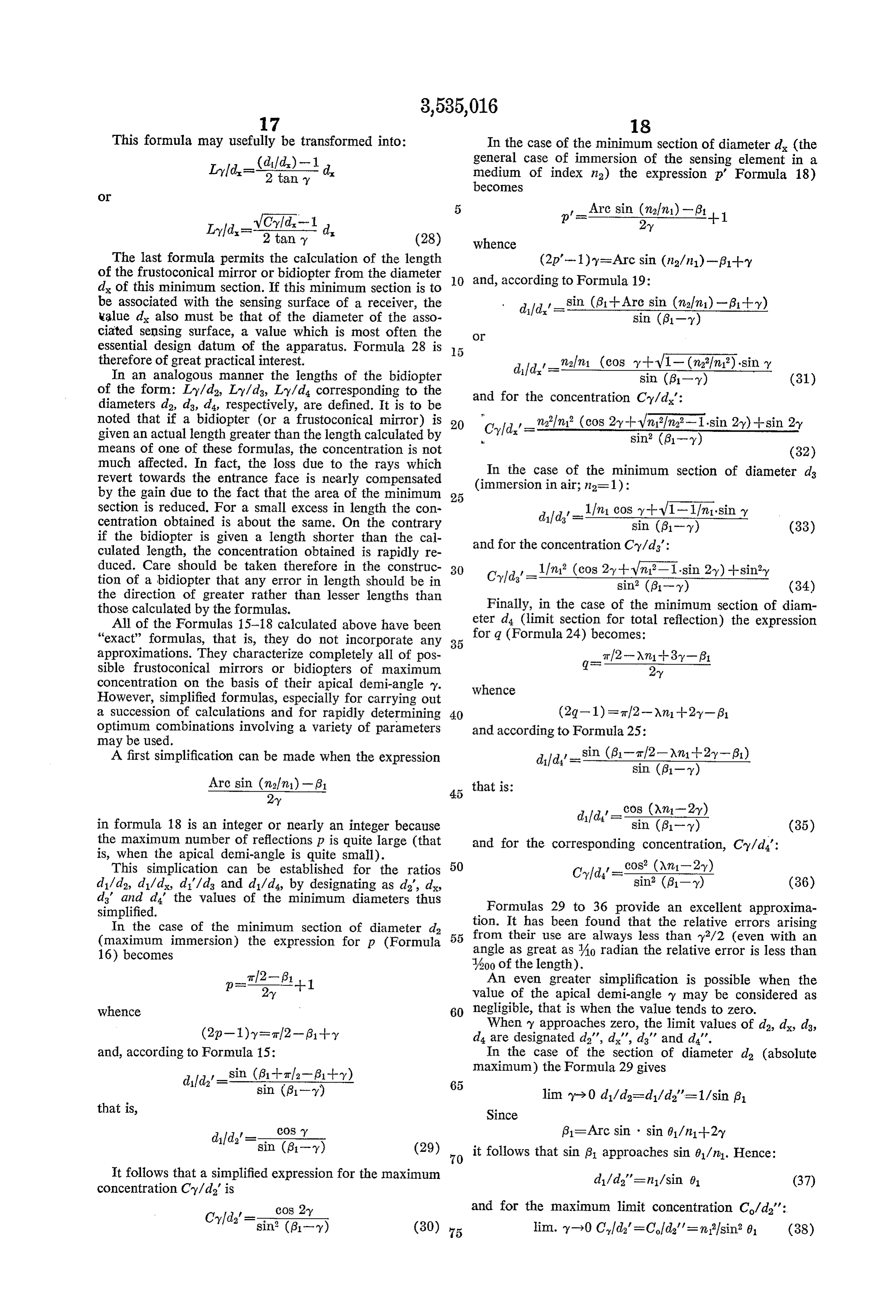
This formula may usefully be transformed into: In the case of the minimum section of diameter d (the general case of immersion of the sensing element in a
Lld-Ed. medium of index n2) the expression p' Formula 18) becomes
VChild-1 Are sin Colna)
The last formula permits the calculation of the length of the frustoconical mirror or bidiopter from the diameter O and, according to Formula 19: d of this minimum section. If this minimum section is to be associated with the sensing surface of a receiver, the d/d , sin. (81-- Arc sin (n/n) - 6 -- y) value d also must be that of the diameter of the asso sin (81-y) ciated sensing surface, a value which is most often the O essential design datum of the apparatus. Formula 28 is therefore of great practical interest. difd alr1 (cos y -- VI- (m/mi) sin y In an analogous manner the lengths of the bidiopter sin (6-y) (31) of the form: Ly/da, Ly/ds, Ly/d corresponding to the and for the concentration Cy/d: diameters d2, d, d4, respectively, are defined. It is to be noted that if a bidiopter (or a frustoconical mirror) is . , malni (cos 2y--wn?fn-Isin 2y)--sin 2-y given an actual length greater than the length calculated by 20 h:Cyld.' = all as it sin i?(61-y) on 21 St. 2 means of one of these formulas, the concentration is not (32) much affected. In fact, the loss due to the rays which In the case of the minimum section of diameter d8 revert towards the entrance face is nearly compensated by the gain due to the fact that the area of the minimum 25 (immersion in air; n2=1):
section is reduced. For a small excess in length the con difd -111 cos y --V1-1/ni-sin y centration obtained is about the same. On the contrary 3 sin (61-y) (33) if the bidiopter is given a length shorter than the cal and for the concentration Cy/d: culated length, the concentration obtained is rapidly re duced. Care should be taken therefore in the construc 30 Cyld' 1?n12 (cos 2-y--wni?-1-sin 2-y)--siny tion of a bidiopter that any error in length should be in Y103 sin (61-y) (34) the direction of greater rather than lesser lengths than those calculated by the formulas. Finally, in the case of the minimum section of diam All of the Formulas 15-18 calculated above have been eter d4 (limit section for total reflection) the expression "exact” formulas, that is, they do not incorporate any 35 for q (Formula 24) becomes:
approximations. They characterize completely all of pos Tl2-An-1-8-61 sible frustoconical mirrors or bidiopters of maximum concentration on the basis of their apical demi-angle ?y. whence
However, simplified formulas, especially for carrying out a succession of calculations and for rapidly determining 40 (2g-1) = 1/2-An-2-y-61 optimum combinations involving a variety of parameters and according to Formula 25:
may be used.
A first simplification can be made when the expression dild' sin (61-Tl2-An1+2Y-6)
that is:
in formula 18 is an integer or nearly an integer because sin (61-y) (35) the maximum number of reflections p is quite large (that and for the corresponding concentration, Cy/d: is, when the apical demi-angle is quite small).
This simplication can be established for the ratios 50 cos' (Ani-2y) d1/da, d/dx d/d and d/d4, by designating as d", d. Cld'-i-. (36) d' and d" the values of the minimum diameters thus Formulas 29 to 36 provide an excellent approxima simplified.
In the case of the minimum section of diameter da tion. It has been found that the relative errors arising (maximum immersion) the expression for p (Formula 55 from their use are always less than y?/2 (even with an angle as great as Ao radian the relative error is less than 16) becomes 400 of the length).
arl2-61 --1 An even greater simplification is possible when the value of the apical demi-angle y may be considered as whence 60 negligible, that is when the value tends to zero. (2p-1) y= 1/2-?31-Hy When y approaches zero, the limit values of d, d, d3, d4 are designated da', d', d' and d'.
and, according to Formula 15: In the case of the section of diameter d (absolute sin (81--atla-B1-y) maximum) the Formula 29 gives
that is, Since cos y (31=Arc sin sin 01/n--2-y dilds'=sin(i) (29) 70 it follows that sin 61 approaches sin 01/n. Hence: It follows that a simplified expression for the maximum di/da'= n.1/sin 61 (37) concentration Cy/d' is and for the maximum limit concentration C/d':
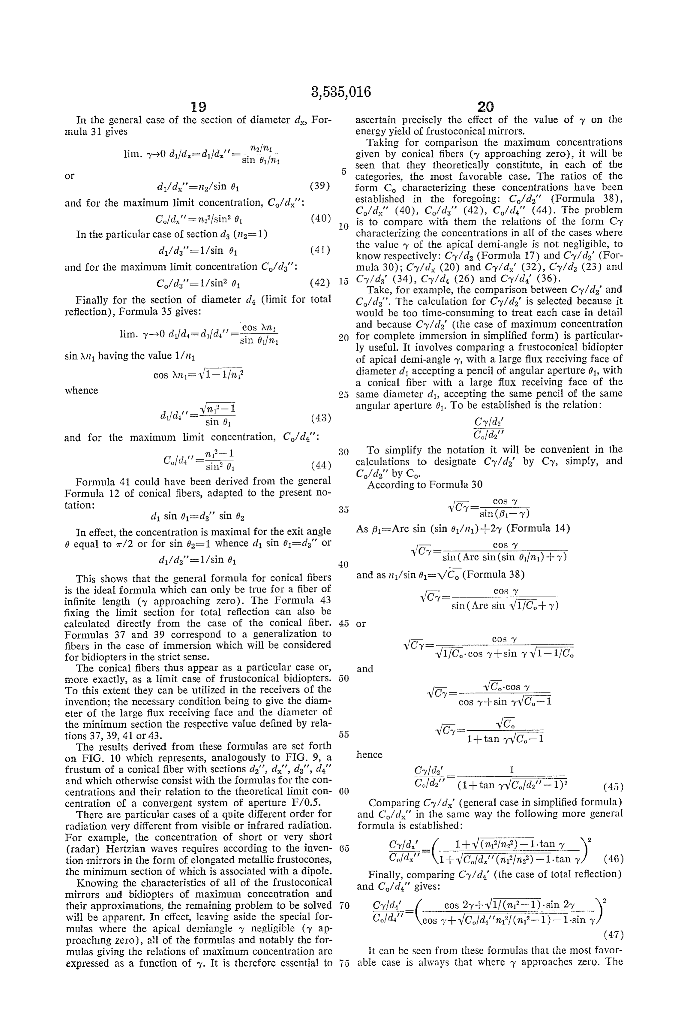
sin? (6-y) (30) 75 lim... y->0 Clda' = Cold' = mi?sin 6 (38)
Page 18
In the general case of the section of diameter d, For ascertain precisely the effect of the value of y on the mula 31 gives energy yield of frustoconical mirrors. Taking for comparison the maximum concentrations lim. Y-0 di?d-dild."=E, given by conical fibers (y approaching zero), it will be 5 seen that they theoretically constitute, in each of the
Ot categories, the most favorable case. The ratios of the d/dx'= n.2/sin 61 (39) form Co characterizing these concentrations have been and for the maximum limit concentration, Co/d': established in the foregoing: C/d' (Formula 38),
Cld's r misin? 0. (40) 0. is to compare with them the relations of the form Cy In the particular case of Section da (n=1) characterizing the concentrations in all of the cases where d/d'=1/sin 01 (4d.) the value y of the apical demi-angle is not negligible, to know respectively: Cy/d (Formula 17) and Cy/d' (For and for the maximum limit concentration Co/da': mula 30); Cy/dx (20) and Cy/d (32), Cy/d (23) and C/d'= 1/sin 61 (42) Cy/d (34), C-y/d (26) and Cy/d (36).
Take, for example, the comparison between Cy/d' and
Finally for the section of diameter d (limit for total C/d'. The calculation for Cy/d' is selected because it reflection), Formula 35 gives: would be too time-consuming to treat each case in detail cos An and because Cy/d' (the case of maximum concentration
lim. y-y0 dild- did Tsin (if n-1 for complete immersion in simplified form) is particular ly useful. It involves comparing a frustoconical bidiopter sin. An having the value 1/n. of apical demi-angle y, with a large flux receiving face of cos An= Vl-lfin diameter d1 accepting a pencil of angular aperture 01, with whence a conical fiber with a large flux receiving face of the 2 5 same diameter d, accepting the same pencil of the same
22, 1 . angular aperture 01. To be established is the relation:
did' = sin () (43) Cyld' and for the maximum limit concentration, Co/da': Cof d' , n -1 30 To simplify the notation it will be convenient in the Cld."-ing, (44) calculations to designate Cy/d by Cy, simply, and
Formula 41 could have been derived from the general According to Formula 30 Formula 12 of conical fibers, adapted to the present no tation:
In effect, the concentration is maximal for the exit angle As (31=Arc sin (sin 01/n)--2y (Formula 14) 0 equal to 7t/2 or for sin 62=1 whence d1 sin 61=ds' or - Y -
sin (Arc sin (sin 01/mi) -- y)
This shows that the general formula for conical fibers and as n1/sin 6, =VCo (Formula 38) is the ideal formula which can only be true for a fiber of l,
infinite length (y approaching zero). The Formula 43 sin (Arc sin V1/C+ y) fixing the limit section for total reflection can also be calculated directly from the case of the conical fiber. O
Formulas 37 and 39 correspond to a generalization to
fibers in the case of immersion which will be considered for bidiopters in the strict sense. VIIC.cos sinY -
The conical fibers thus appear as a particular case or, and more exactly, as a limit case of frustoconical bidiopters.
To this extent they can be utilized in the receivers of the invention; the necessary condition being to give the diam VC,--cos y +sinitsy VC-1
eter of the large flux receiving face and the diameter of the minimum section the respective value defined by rela tions 37, 39, 41 or 43. 55 VC,--1--tan y VC-1
The results derived from these formulas are set forth on FIG. 10 which represents, analogously to FIG. 9, a hence frustum of a conical fiber with sections d', d', d', d' 3'-- - and which otherwise consist with the formulas for the con Cofida' (1-- tan V.C.?d' - 1)2 (45) centrations and their relation to the theoretical limit con 60 centration of a convergent system of aperture F/0.5. Comparing Cy/d' (general case in simplified formula) There are particular cases of a quite different order for and Co/d' in the same way the following more general radiation very different from visible or infrared radiation. formula is established:
For example, the concentration of short or very short (radar) Hertzian waves requires according to the inven Cyld." -( 1 + V (n?fn?)-1.tany ) tion mirrors in the form of elongated metallic frustocones, Cold.' V1-- WCld." (n.2/n) - I.tan / (46) the minimum section of which is associated with a dipole. Finally, comparing Cy/d' (the case of total reflection) Knowing the characteristics of all of the frustoconical and C/d' gives:
mirrors and bidiopters of maximum concentration and their approximations, the remaining problem to be solved 70 SA-( COS 2-y--V11 (n?- 1). sin 2-y ) will be apparent. In effect, leaving aside the special for Cold' \cos -- WCld,"n? (n,2-1)-1.sin mulas where the apical demiangle y negligible (ty ap (47) proaching zero), all of the formulas and notably the for mulas giving the relations of maximum concentration are it can be seen from these formulas that the most favor expressed as a function of y. It is therefore essential to 5 able case is always that where y approaches zero. The
Page 19
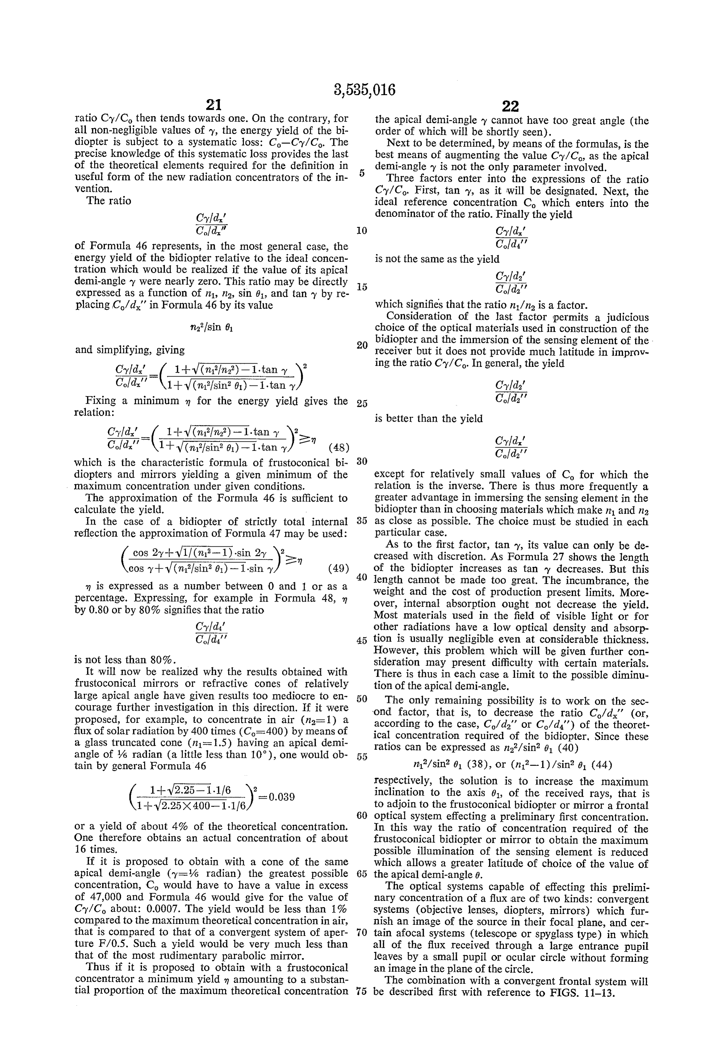
ratio Cy/Co then tends towards one. On the contrary, for the apical demi-angle y cannot have too great angle (the all non-negligible values of y, the energy yield of the bi order of which will be shortly seen). diopter is subject to a systematic loss: Co-Cy/Co. The Next to be determined, by means of the formulas, is the precise knowledge of this systematic loss provides the last best means of augmenting the value Cy/C, as the apical of the theoretical elements required for the definition in demi-angle y is not the only parameter involved. useful form of the new radiation concentrators of the in Three factors enter into the expressions of the ratio vention. Cy/Co. First, tan y, as it will be designated. Next, the The ratio ideal reference concentration Co which enters into the Cyld." denominator of the ratio. Finally the yield
of Formula 46 represents, in the most general case, the energy yield of the bidiopter relative to the ideal concen is not the same as the yield tration which would be realized if the value of its apical demi-angle y were nearly zero. This ratio may be directly 5 expressed as a function of n.1, ng, sin 61, and tan y by re placing C/d' in Formula 46 by its value which signifies that the ration1/n is a factor. Consideration of the last factor permits a judicious choice of the optical materials used in construction of the and simplifying, giving 20 bidiopter and the immersion of the sensing element of the receiver but it does not provide much latitude in improv ing the ratio Cy/Co. In general, the yield
Cld.' 1- W (mi?sin 0)-1.tan y Cylds'
Fixing a minimum n for the energy yield gives the 25 Cld' relation:
is better than the yield
which is the characteristic formula of frustoconical bi 30 diopters and mirrors yielding a given minimum of the except for relatively small values of C for which the maximum concentration under given conditions. relation is the inverse. There is thus more frequently a The approximation of the Formula 46 is sufficient to greater advantage in immersing the sensing element in the calculate the yield. bidiopter than in choosing materials which make n and n.2 In the case of a bidiopter of strictly total internal as close as possible. The choice must be studied in each reflection the approximation of Formula 47 may be used: particular case.
As to the first factor, tan ?y, its value can only be de ( cos 2y+ V11 (n-1)-sin 2-y 'a-n creased with discretion. As Formula 27 shows the length cos y + w(n/sino)-1-siny/ (49) 40 of the bidiopter increases as tan y decreases. But this m is expressed as a number between 0 and 1 or as a length cannot be made too great. The incumbrance, the percentage. Expressing, for example in Formula 48, m weight and the cost of production present limits. More by 0.80 or by 80% signifies that the ratio over, internal absorption ought not decrease the yield. Most materials used in the field of visible light or for
Cyld' other radiations have a low optical density and absorp
Cld' 45 tion is usually negligible even at considerable thickness.
However, this problem which will be given further con is not less than 80%. sideration may present difficulty with certain materials. It will now be realized why the results obtained with There is thus in each case a limit to the possible diminu frustoconical mirrors or refractive cones of relatively tion of the apical demi-angle.
large apical angle have given results too mediocre to en 50 The only remaining possibility is to work on the sec courage further investigation in this direction. If it were proposed, for example, to concentrate in air (n2=1) a ond factor, that is, to decrease the ratio Co/d' (or, according to the case, C/d' or C/d') of the theoret flux of solar radiation by 400 times (Co=400) by means of ical concentration required of the bidiopter, Since these a glass truncated cone (n=1.5) having an apical demi angle of y& radian (a little less than 10), one would ob 55 ratios can be expressed as n2/sin 61 (40) tain by general Formula 46 n/sin? 01 (38), or (n12-1)/sin? 8 (44) respectively, the solution is to increase the maximum
inclination to the axis 01, of the received rays, that is to adjoin to the frustoconical bidiopter or mirror a frontal 60 optical system effecting a preliminary first concentration.
or a yield of about 4% of the theoretical concentration. In this way the ratio of concentration required of the One therefore obtains an actual concentration of about frustoconical bidiopter or mirror to obtain the maximum 16 times. possible illumination of the sensing element is reduced If it is proposed to obtain with a cone of the same which allows a greater latitude of choice of the value of apical demi-angle (y=% radian) the greatest possible the apical demi-angle 0.
concentration, C would have to have a value in excess The optical systems capable of effecting this prelimi of 47,000 and Formula 46 would give for the value of nary concentration of a flux are of two kinds: convergent Cy/C about: 0.0007. The yield would be less than 1% systems (objective lenses, diopters, mirrors) which fur compared to the maximum theoretical concentration in air, nish an image of the source in their focal plane, and cer that is compared to that of a convergent system of aper 70 tain afocal systems (telescope or spyglass type) in which ture F/0.5. Such a yield would be very much less than all of the flux received through a large entrance pupil that of the most rudimentary parabolic mirror. leaves by a small pupil or ocular circle without forming Thus if it is proposed to obtain with a frustoconical an image in the plane of the circle.
concentrator a minimum yield in amounting to a substan The combination with a convergent frontal system will tial proportion of the maximum theoretical concentration 75 be described first with reference to FIGS. 11-13.
Page 20
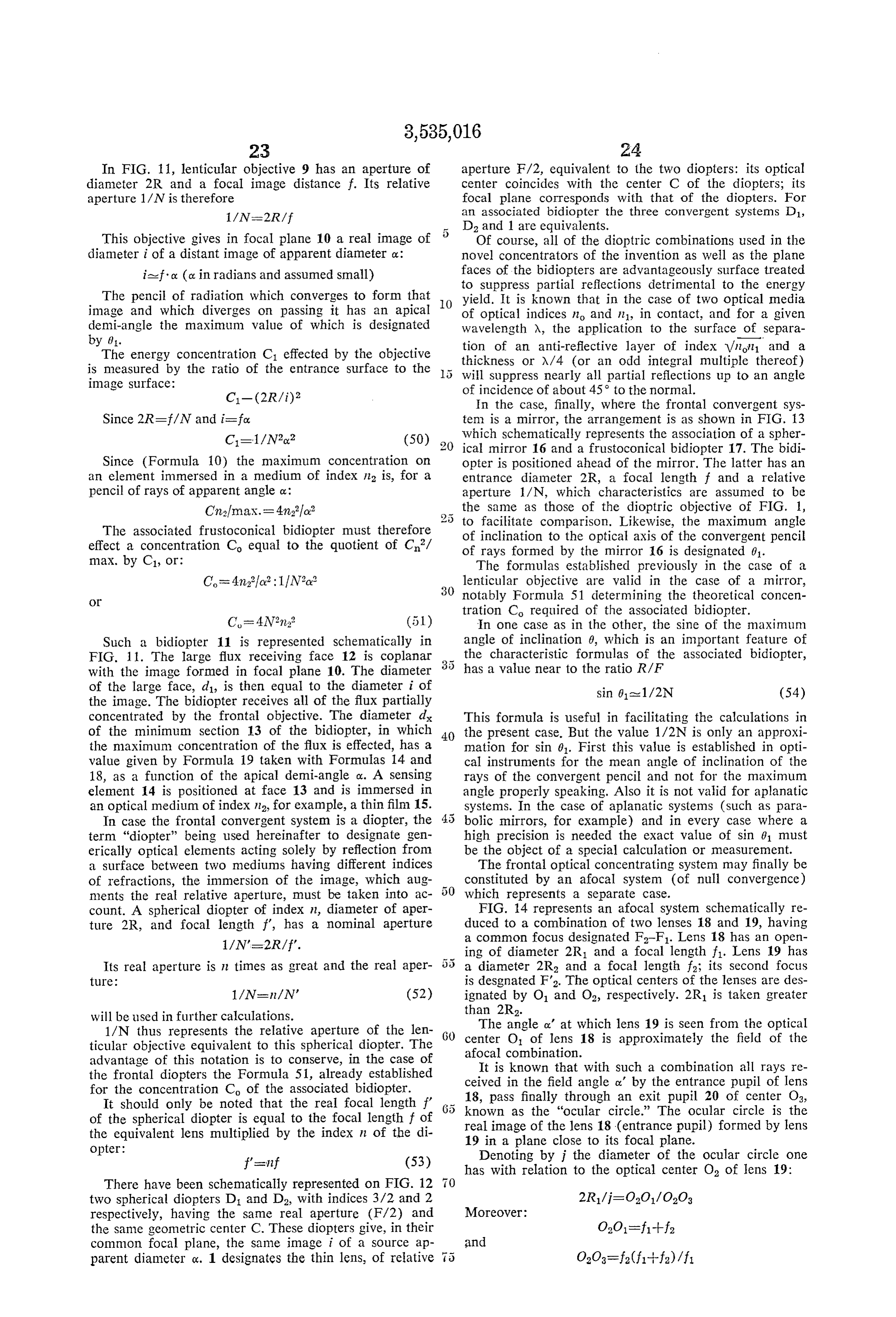
In FIG. 11, lenticular objective 9 has an aperture of aperture F/2, equivalent to the two diopters: its optical diameter 2R and a focal image distance f. Its relative center coincides with the center C of the diopters; its aperture 1/N is therefore focal plane corresponds with that of the diopters. For an associated bidiopter the three convergent systems D1,
D2 and 1 are equivalents.
This objective gives in focal plane 10 a real image of 5 Of course, all of the dioptric combinations used in the diameter i of a distant image of apparent diameter ox: novel concentrators of the invention as well as the plane ia-foc (c. in radians and assumed small) faces of the bidiopters are advantageously surface treated to suppress partial reflections detrimental to the energy
The pencil of radiation which converges to form that O yield. It is known that in the case of two optical media image and which diverges on passing it has an apical of optical indices no and n1, in contact, and for a given demi-angle the maximum value of which is designated wavelength A, the application to the surface of separa by 61. tion of an anti-reflective layer of index Vnn and a The energy concentration C. effected by the objective thickness or X/4 (or an odd integral multiple thereof) is measured by the ratio of the entrance surface to the will suppress nearly all partial reflections up to an angle image surface: of incidence of about 45° to the normal. In the case, finally, where the frontal convergent sys ten is a mirror, the arrangement is as shown in FIG. 13 which schematically represents the association of a spher ical mirror 16 and a frustoconical bidiopter 17. The bidi
Since (Formula 10) the maximum concentration on opter is positioned ahead of the mirror. The latter has an an element immersed in a medium of index n is, for a entrance diameter 2R, a focal length f and a relative pencil of rays of apparent angle ce: aperture 1/N, which characteristics are assumed to be Cnfmax. = 4nala? the same as those of the dioptric objective of FIG. 1, 2 5 to facilitate comparison. Likewise, the maximum angle
The associated frustoconical bidiopter must therefore of inclination to the optical axis of the convergent pencil effect a concentration C equal to the quotient of C/ of rays formed by the mirror 16 is designated 0. maX. by C1, or: The formulas established previously in the case of a lenticular objective are valid in the case of a mirror, 30 notably Formula 51 determining the theoretical concen tration Co required of the associated bidiopter.
In one case as in the other, the sine of the maximum
Such a bidiopter 11 is represented schematically in angle of inclination 0, which is an important feature of FIG. 1 1. The large flux receiving face 12 is coplanar the characteristic formulas of the associated bidiopter, with the image formed in focal plane 10. The diameter has a value near to the ratio R/F of the large face, d, is then equal to the diameter i of sin 61-1/2N (54) the image. The bidiopter receives all of the flux partially concentrated by the frontal objective. The diameter d This formula is useful in facilitating the calculations in of the minimum section 13 of the bidiopter, in which 40 the present case. But the value 1/2N is only an approxi the maximum concentration of the flux is effected, has a mation for sin 01. First this value is established in opti value given by Formula 19 taken with Formulas 14 and cal instruments for the mean angle of inclination of the 18, as a function of the apical demi-angle a. A sensing rays of the convergent pencil and not for the maximum element 14 is positioned at face 13 and is immersed in angle properly speaking. Also it is not valid for aplanatic an optical medium of index n2, for example, a thin film 15. Systems. In the case of aplanatic systems (such as para In case the frontal convergent system is a diopter, the bolic mirrors, for example) and in every case where a term “diopter” being used hereinafter to designate gen high precision is needed the exact value of sin () must erically optical elements acting solely by reflection from be the object of a special calculation or measurement. a surface between two mediums having different indices The frontal optical concentrating system may finally be of refractions, the immersion of the image, which aug constituted by an afocal system (of null convergence) ments the real relative aperture, must be taken into ac which represents a separate case. count. A spherical diopter of index n, diameter of aper FIG. 14 represents an afocal system schematically re ture 2R, and focal length f', has a nominal aperture duced to a combination of two lenses 18 and 19, having a common focus designated F-F1. Lens 18 has an open ing of diameter 2R1 and a focal length f. Lens 19 has
Its real aperture is in times as great and the real aper 5 5 a diameter 2R2 and a focal length f; its second focus ture: is desgnated F2. The optical centers of the lenses are des 1/N-n/N' (52) ignated by O1 and O2, respectively. 2R1 is taken greater will be used in further calculations. than 2R2.
1/N thus represents the relative aperture of the len The angle ox' at which lens 19 is seen from the optical ticular objective equivalent to this spherical diopter. The GO afocal center O of lens 18 is approximately the field of the combination.
advantage of this notation is to conserve, in the case of It is known that with such a combination all rays re the frontal diopters the Formula 51, already established ceived in the field angle o' by the entrance pupil of lens for the concentration C of the associated bidiopter. 18, pass finally through an exit pupil 20 of center Oa, It should only be noted that the real focal length f' known as the "ocular circle.' The ocular circle is the of the spherical diopter is equal to the focal length f of real image of the lens 18 (entrance pupil) formed by lens the equivalent lens multiplied by the index n of the di 19 in a plane close to its focal plane. opter: Denoting by j the diameter of the ocular circle one f's-inf (53) has with relation to the optical center O of lens 19:
There have been schematically represented on FIG. 12 two spherical diopters D1 and D, with indices 3/2 and 2 respectively, having the same real aperture (F/2) and the same geometric center C. These diopters give, in their common focal plane, the same image i of a source ap parent diameter ox. 1 designates the thin lens, of relative
Page 21
whence Consider a given combination of a frontal concentra tor and a bidiopter of field e and a source of apparent di
The energy concentration Ca of the afocal combina ameter ox of which a flux of radiation is to be concen tion in relation to the ratio of the diameter of the en trated.
trance pupil 2R1 to the diameter i of the exit pupil is: The angle of the field e is determined by the diameter d of the large flux receiving face of the bidopter and the focal length f (or its equivalent) of the frontal concen
To avoid changing notations, the relative aperture of a trating system according to the relation: convergent system of equivalent effectiveness as the pres eased/f ent afocal system in concentrating a given flux of appar O ent angle cy', may be designated as 1/N. This convergent (d. being the diameter of the image or of the ocular cir system must have a diameter of aperture equal to 2R1. cle for the angle of field e).
and must form with the given flux an image of diameter The first condition for receiving a flux of radiation equal to i. It is then defined by the two following rela from the source is obviously that it be situated in the tions, designating its focal length by f: 15 field e. If this is the case, two cases are to be considered 1/N=2R/f (a convergent frontal concentrator forming an image being assumed):
j=f.o.' The field e is smaller or at most equal to the apparent giving diameter ox of the source and the concentration of the 1/N=2Rox'/i 20 received flux is effected at the maximum.
whence Or, on the hand, edo and the concentration is not 1/N=f/fox' (56) maximal. In effect the frontal conversion system pro
Utilizing this notation of equivalence Formula 55 for the vides an image of the source of diameter isfo. energy concentration Ca becomes: This image is smaller than the large flux entrance face 25 of the associated bidiopter the diameter of d of which is:
This is of the same form as the relation 50 giving the ratio of energy concentration C1 in the case of a lenticular The concentration effected by the bidiopter in the objective. plane of its minimum section of diameter d is the equal As for calculating the concentration Co required of the 30 (i/d)?, a ratio which is smaller than the maximum ratio associated frustoconical bidiopter (the large entrance face (d/d).
of which is positioned in coincidence with the ocular An analogous reasoning may be carried out in the case circle), it is accomplished by simply replacing N in For of an afocal frontal concentrating system. The diameter mula 51 by its value from 56 as a function of the three of the ocular circle remains invariable and is the value values f. f. and cy' characterizing the afocal frontal System. of the maximum angle 61 of the rays passing the ocular Thus, thanks to the convention of energy equivalence, circle which is found to be less than the value for maxi the expression 1/N which appears in the fundamental mum concentration.
definition of the novel concentrator preserves the same In this case, as in that of the convergent frontal system, usage in the case of an afocal frontal system as in the 40 the ratio between the concentratition obtained and the ho case of a convergent System. maximum concentration is approximately equal to (c/e). In particular, the sines of the maximum angle of in this It will be seen that for certain very particular applications clination 01 to the optic axis of the rays emerging from the ject ofmay be satisfactory but this is not the principal ob ocular circle preserve the same approximate value: 1/2N. the invention.
There is shown in FIG. 14 a ray 2 having at its exit from It is thus clear that to obtain by means of a simple bidiopter, associated in a simple manner with a frontal the afocal system that maximum inclination 01. There 45 concentrating are also shown in this figure several rays, such as 22 and system, the maximum concentration of a 23, which are found to be outside of the real field of the flux emitted by a source, the optical axis of the con system to show that ray 21 is indeed the one which has centrator must be directed at the source of radiation and the angle of the field of the concentrator (frontal system the maximum inclination of those passing through the plus bidiopter) must have a value smaller or at most equal ocular circle 20. 50
Designating by E the intersection of ray 21 with the to the apparent diameter of the source. focal plane passing through F2-F1, the direction of ray 21 tions In many cases the realization of the necessary condi after leaving lens 19 is parallel to OE so that does not present any particular difficulty. This is true when the Source is well defined, easily
Angle EO2F2=0.1 55 located and of known apparent diameter, as is the case but with most laboratory radiation concentrators (photocells, bolometers, photomultipliers, scintillation counters, nu clear radiation detectors, spectrophotometers, etc.) or
OF2=f for a solar energy concentrator, for example. In the so that 60 latter case it is sufficient to impress on the concentrator sin 012 f/fox/2 a movement which causes it to follow the sun in its and according to the equivalence relation 56: course using devices already known for traditional solar energy receivers.
sin 9-1/2N In the case of so called “active' detectors using an The combination of a frontal concentrating system (con 65 emitter which scans by mechanical means a certain area vergent or afocal) and a frustoconical bidiopter or mir of space with a concentrated beam of radiation (generally ror of maximum concentration being thus defined, the es in the infrared or in very short Hertzian waves-"radar') sential problem is the efficiency of such a combination for it is sufficient to give the concentrator an angle of field a source of radiation of any diameter situated in any field. at least equal to the apparent diameter of the zone In effect, in the cases which will be studied to establish 70 “lighted' by the emitter at the mean distance of use, the formulas, the combination of the frontal system and and to give the concentrator a sweep movement adjusted the associated bidiopter has been selected so that its field so that its optical axis remains parallel to that of the is equal to the apparent angle of the source, its optical emitter. This method of operation is used in certain of axis being understood to pass through the source. The the apparatus applying the principles of the invention and actual conditions of use are usually quite different. 75 it will be found that it is possible in this way to pro
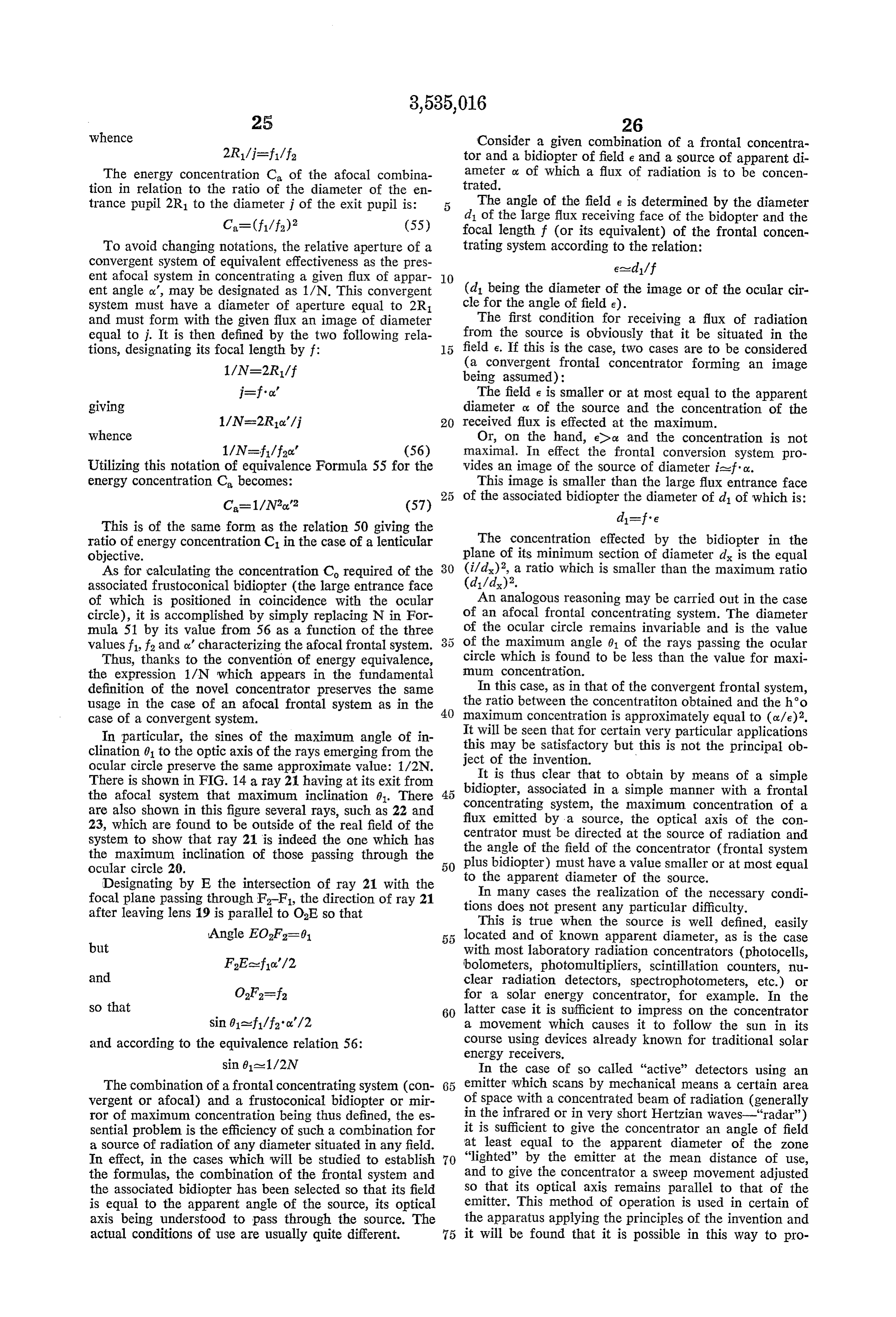
Page 22
vide a simple infrared detector, for example, from 100 the maximum concentration as previously defined, the to 500 times more sensitive than the detector now in angle e must be smaller than or at most equal to the use under the same conditions. apparent diameter of the Smallest of the Sources to be de In the same order of ideas the characteristics of the tected or observed. Each concentrator has, therefore, a present invention may be combined with the scanning 5 well defined limit of maximum efficiency and mean dis emitters and receivers described in French Pat. 1,358,366 tance of utilization. For example, a concentrator for which of June 15, 1962 to the present applicant, the character e=A000 radian (326'), and e/d-100, can concentrate istics of which give considerable physiological advantages in maximal manner, in a field T of nearly 6, the flux for ocular observations. emanating from all sources or objects having an apparent In all other cases, that is, when no mechanical arrange diameter greater than or at least equal to A000 radian ment for scanning is preexistent, and there is a Surplus (that is, 10 cm. at 100 meters or 1 meter at 1 kilometer). of variable emitting or reemitting sources of indetermi The resolving power of such a combination is practically nate or unknown position, it is necessary to adjoin to equivalent to that of the human eye in broad daylight. the concentrator of the invention automatic scanning The applications of this type of concentrator (bundle mechanism permitting the exploration of a region of space of bidiopters) are very numerous and extend to all cases until a radiation of flux to be concentrated is received. where it is desirable to obtain a permanent image by Devices of this kind will be described in particular cases, Simple means (photographic apparatus, image tubes, meta notably for searching heads, but usually this mode of Scopes and phosphoresent viewers, radioScopes . . .). It operation is least convenient. will be seen that another advantage of bundles of bi It is easy to mitigate this difficulty in two other ways. : diopters is that they have a considerably shorter length for A distinction is to be drawn between the case where the the same concentration and yield. frontal concentrating system is convergent and that where If it is desired to convert a given concentrator to per it is afocal. When the system is convergent (forming an mit maximal operation on sources of Smaller size than image), on the one hand, a bundle of bidiopters may had been foreseen (for example, receding Sources), there be used instead of a single bidiopter, which increases the 2 5 may be added to the frontal objective a further optical total field without diminishing the efficiency of each par combination, such as a telephoto lens or a variable focus ticular elementary bidiopter. Or, on the other hand, the system. The images of the sources are then enlarged and image formed by the frontal system (receiving radiation the total field is, as expected, reduced. over a large field) can be subjected to optical scanning The second Solution may be realized in several ways by known means, which automatically bring at a certain and may employ any of the known optical scanning moment the image of the source into coincidence with methods. For example, in front of the combination of a the flux receiving face of the associated bidiopter. frontal convergent or a focal system and associated bi When the frontal system is afocal, optical Scanning diopter of field e, may be added an arrangement of moving is possible only ahead of the system, equivalent to an mirrors or prisms, or a Nipkov disk or any other optical angular scanning of the field, the ocular circle remaining scanning device. The image of constant size then reflects of constant size equal to that of the large face of the Successively the various elementary regions (of apparent associated bidiopter. angle e) of the scanned field. On the other hand certain The first of these solutions (the bundle of bidiopters) elements of the concentrator (having a field I)e) are has the advantage of providing a permanent image or 1-0 moved with respect to others. For example, the convergent at least a permanent localization of the emitting source frontal system may be displaced in a plane perpendicular in a given field. The principle of operation will be briefly to the optical axis causing a symmetrical movement of described with reference to FIG. 15 which represents the image in the focal plane, which has the effect of bring schematically a convergent objective 24, having an aper ing Successive different elementary regions (of apparent ture diameter 2R, a focal length f and a relative aperture angle e) of the image into coincidence with the flux re 1/N. In its focal plane 25 is positioned the ensemble ceiving face of the associated bidiopter. Again, the frontal of large flux entrance faces of a bundle 26 of frustoconical convergent System may be fixed and the associated bi diopter displaced parallel to itself, its flux receiving face bidiopters such as 27. d designates the diameter of the coming Successively into coincidence with each elementary large flux entrance face of one of the elementary bidi region of the image. All the combination of the different opters, e designates the diameter of the ensemble of modes of operation are possible. The methods of image large flux entrance faces, d designates the diameter of the minimum section of one of the elementray bidiopters Scanning are known in themselves and will not be de and e designates the diameter of the ensemble of mini Scribed in detail. Only the results will be set forth. mum sections. Consider a bidiopter having a large flux receiving face The total field of the concentrator is an angle T (FIG. 5 5 of diameter d, such as is represented at 28 in FIG. 15. Its 15) defined by the ratio: optical axis coincides with that of the associated con Tale/f Vergent frontal System 24 with the characteristics previ ously defined: e1, the diameter of the total image formed
The field relative to one of the elementary bidiopters, in the focal plane; I, the total field and e, the field of the such as 27, is an angle e, previously defined by the bidiopter 28.
ratio: 60 The Scan is periodic and generally continuous. In the eased/f course of the Scanning cycle each of the elements of
Of the ensemble of objects situated in the field T, the diameter d, contained in the image of diameter e1, must objective 24 provides an image of diameter e1, which coincide once with the large flux receiving face 29 of the is in effect analysed by the elementary bidiopters. The bidiopter. In general, a horizontal or vertical Sweep in angle e measures the limit of angular separation (resolv adjacent parallel bands is used. The Scanning frequency ing power) of the concentrator may have a wide range of values according to the condi tions of operation and the results desired. When the re ceiver is used for ocular observation with the human eye,
The angle e may be very small (when using a bundle the scanning characteristics and mode of observation de of glass fibers, for example) and correspond to a precise scribed in the present applicant's French Pat. No. 1,358,- image of the emitting object. It may on the other hand be 366 of June 15, 1962 may be used. Arresting and control very large (with a bundle of relatively large bidiopters) arrangements for holding the bidiopter on a particular and correspond only to a rough localization of the more source region or for following the displacement of a Source important sources in a given field. In both cases, to obtain region may be provided.
Page 23
In its direct use this method of optical scanning does most equal to the area of the terminal section of each of not provide an image since the associated bidiopter is the bidiopters of the bundle.
unique. The same is true of mechanical scanning in active The features of the novel concentrator of the invention or in passive detection. In all of these cases it is neverthe are now becoming apparent.
less possible to reconstitute an image of the scanned field To concentrate a flux of radiation emanating from a on the basis of variations in successive illuminating energy Source of apparent angle o, embracing a total field I, a in the plane of the minimum section of the bidiopter. In frontal concentrating system of field T, of relative aper effect, the successive variations in illumination have a ture 1/N and of focal length f, is associated with at least unique relation with the variation in radiation of the one frustoconical bidiopter or mirror of field e such that elementary regions of the scanned field of objects. To ob IO esco.
tain an image of the ensemble of objects requires the Thus in every case where the frustoconical bidiopter same unique relation between the variations of illumina or mirror forms an element of a bundle or where it is tion of the small section of the bidiopter and the varia alone and is illuminated by a scanner, the diameter di fions of luminosity on a fluorescent screen of suitable per of its large flux receiving face is always sistence. This is exactly what is done in certain television 5 disfe (58) systems which operate with a single photoelectric cell (without iconoscope), such as the old Nipkov camera. This bidiopter will in every case be designated “the ele In certain cases the transduction into an image may be mentary bidiopter” even when it is sole and even when effected directly, without the intervention of electronic the total field T is equal to the angle e as in certain solar arrangements. For example, in the case where the asso 20 concentrators, for example, or in certain laboratory con ciated bidiopter scans the frontal image by displacement centrators. in the case of frustoconical mirrors, in anal parallel to itself, it is sufficient to position a fluorescent Ogous manner, the "elementary frustoconical mirror' screen at the plane of the small face of the bidiopter in must be considered.
order to obtain an image. It is the elementary bidiopter or the elementary frusto The two types of solution may also be combined, that 25 conical mirror which is specified above in the fundamen is, by using both a bundle of bidiopters and a scanning tal definition of the apparatus of the invention, and it is of the image. The angle of the field of the bundle is then to these elements that nearly all of the formulas which reduced and scanning is simplified. This combination has have been calculated are directed. The notations are in various practical advantages (larger total field and pos variable: d is always the diameter of the large flux re sibility of immediate localization in the small elementary 30 ceiving face of the elementary bidiopter, d. is the diameter field). It leads to a series of apparatus arrangements em of the minimum section and y is the apical demi-angle bodying the principles of the invention. of the cone.
Finally, a further important aspect of the problem of Therefore the foregoing formulas permit the precise the real efficiency of the concentrator is posed by its asso determination of the elementary bidiopter or frusto ciation with the sensing element. 35 conical mirror in every case. However, before proceeding This element is most frequently present in the form of With such determinations it is necessary, in each particu a sensing surface: a thin plate or ribbon. It has been said, lar case, that a preliminary idea be formed of the order in a general way, that the diameter of the minimum of magnitude of the characteristics in order to be able Section of the bidiopter (or of the bundle) at which the 40 to make overall adjustments in the numerous parameters concentration attains its maximum value, must be equal which are involved.
to the diameter of the associated sensing surface. But it It is possible to do this on the basis of Formula 51 must be noted that there are two types of sensing surfaces: defining the concentration C required of an elementary those which can effectively utilize an image, and those bidiopter as a function of the relative aperture 1/N which react only to the integrated sum of the illumina of the frontal optical system and of the index n of the tion which they receive. 45 medium in which the sensitive element of the receiver is The first type, which may be designated type A, react immersed:
to the energy of illumination at each point of the surface as if the points were independent, within the limit im posed by their discontinuous structure (resolving power). of Knowing Co and d (by Formula 58) an idea of the order magnitude of the dimensions of the bidiopter can be
Among this type are: the retina of the eye, photographic 50 obtained.
plates, mosaic cells, etc. The second type, type B, do not Calling do the theoretical value of the diameter of the differentiate in reaction to illumination of different par ticular points of the surface. This type includes: photo minimum section of the diopter, since d/d=VC electric cells, the metallic ribbons and thermistors of d/do=2Nna (59) bolometers, photoconductive cells, photopiles, etc. 55
However, the combinations of the different types of This calculation can also be made in another sense if Sensing surfaces with the concentrators of the invention Co and the order of magnitude of d are known, for cannot be the same. Particularly a bundle of bidiopters example, when the diameter of the sensing surface asso can only be properly associated with a sensing surface ciated with the minimum section of the bidiopter is given. of type A. Consider an association of the ensemble of 60 Formula 59 then gives the order of magnitude of d. Small terminal faces of a bundle and a sensing surface of And, the field e being generally imposed, the focal length type B of the same over-all diameter. If one of the ele f is definitively determined by the Formula 58: f=d/e. mentary bidiopters of the bundle has effected a maximum Since the angle e may be very small the value off thus concentration of a flux emanating from a source, in a determined may be very large and incompatible with the field angle e, the maximum illumination thus produced 65 practical conditions available. For example, if de0.5 at the end of the bidiopter can only be utilized by the mm., Co=64, and e=A000 radian, d=8X0.5=4 mm., Sensing Surface in a small element of its total surface. and f=4 meters.
Since it can only integrate the elementary illuminations This difficulty can be overcome in two ways: by de which it receives the effect of the concentration is largely creasing the diameter do and that of the associated sensing lost. If e' is the field of angle of the bundle of bidiopters, 70 surface, or by replacing the elementary bidiopter by a the energy concentration effect is divided by (e'/e)2. To bundle of elementary bidiopters each having a smaller conserve the maximum ratio of concentration the sensing minimum diameter do. The choice between these solutions surface of type B must be replaced, either by a surface depends on the type of the associated sensing surface. of type A, or by a mosaic of small surfaces of type B, If the sensing surface is of type B, the second solution the area of each of the Small surfaces being smaller or at 75 cannot be employed directly. The diameter of the sensing
Page 24
surface must be reduced. At the present time a bolometric The combination designated (1) in the last column thermistor, for example, may have the dimensions: of the table is the most acceptable although the relative 0.1 x 0.1 mm. It is to be expected that progress in this aparture (F/2) required of the frontal system may be direction will be made by way of miniaturization. With a little too high for the data of the problem. The length d=0.1 mm., the foregoing calculation would give is satisfactory as the value 220 mm. (for Lo) is too great. f=800 mm. 5 fa better approximation is calculated from Formula 28, There is also the resource of using a prismatic frontal Ly is found to be 198 mm. The combination (2) leads convergent or afocal system to reduce the length. to too long a bidiopter and too low an energy yield. The If the sensing surface is of type A, there is less limita- combination (3) would be excellent if it did not require tion and, notably by using conical fibers, do may be given 0 such a difficult relative aperture (F/1) for the front a very small value. By replacing the elementary bidiopter optical system. The combinations (4) and (5) have a of the foregoing example (do=0.5 mm.) by a bundle of good length but too poor an energy yield. 20 bidiopters, d=25u, d=0.2 mm. and f=200 mm. Of course, the very limited table given by way of This solution may be applied indirectly to Sensing Sur- example only includes some arbitrarily chosen elements faces of type B whenever it is possible to make of them 15 and the proper lengths of a suitable convergent frontal a mosaic of very small independent elements. For ex- system have been omitted to simplify the table. A correct ample, for television cameras there may be made mosaics solution of the problem requires a more precise method of photoelectric cells of cesium on oxidized silver, each of determination of the optimum characteristics of the insulated cell having a diameter of the order of a micron. concentrator and much more complete comparison tables. It remains, to characterize the elementary bidiopter 20. This method constitutes the second aspect of the inven or frustoconical mirror to determine the order of mag- tion and the preceding considerations on the schematic nitude of its length. Formula 28 is transposed replacing elementary bidiopter are only a first approach. Before d by do giving the length Lo describing the method and giving examples of the tables 2N n-1 which it utilizes, further characteristics and important
L= -d, 25 formulas relating to the new concentrator and its bidiop
This formula relates to an imaginary bidiopter or The example outlined above has shown how, in a frustoconical mirror, since on the one hand Co is not the simple case, a compromise between F/N, the resulting real concentration (which would be Cry) and, on the other Co, y, the requirement Cy/Cosen and Lo, may be found. hand, the apical demi-angle y, as yet unknown, enters 30. The problem only poses real difficulty when the ratio C, into Formula 60. The diameter d is thus always too has a high value or when the diameter of the minimum small and the length L is always too large. But the Section of the bidiopter is too large (more than a half formula is very useful in solving the problem of deter- millimeter, for example). It shows that the dimensions mining the characteristics of the elementary bidiopter. It of the bidiopter are functions of each other; if the diameter is notably helpful in selecting a value of y (and that of 35 di of the flux receiving face has a high value, it follows, the energy yield with which it is connected) as it permits as Was Seen, that for a given angle e the focal length of the evaluation in advance of an order of magnitude of the front optical system is greater. It is therefore clear that the length of the bidiopter. The whole practical problem in every case it is desirable to give the diameter d a value is to obtain an advantageous energy yield by choosing as Small as possible and to give the aperture F/N a value C (and thence 1/N) and y so as not to entail too great 40 as large as possible to reduce the ratio C. a length for the bidiopter. Since the possibilites of reducing d. and of increasing It is convenient to call the bidiopter or mirror defined F/N are generally limited, other means of reducing the by d, do, y and Lo "the schematic elementary bidiopter length of the elementary bidiopter or froustoconical or frustoconical mirror.” mirror must be restorted to. This is why the definition An illustrative calculation will explain the considera- 45 of the novel concentrator includes points (3) through tions: (7).
A flux of infrared radiation is to be concentrated by Point (3) relates to the feature of bundles of bidiopters means of a concentrator comprising: previously discussed in connection with the field of the A convergent frontal receiver of relative aperture at concentrator and now considered from the point of view most equal to F/2.5. 50 of its length and energy yield.
A frustoconical bidiopter of vitreous arsenic trisulfide If for a bidiopter of minimum diameter es is substituted (n=2.45) the length of which must not exceed 200 mm. a bundle of elementary bidiopters each having a minimum An associated sensing surface of diameter 0.5 mm. diameter d, Smaller than ex, the length is divided by the immersed in the small face of the bidiopter (n=2.45). ratio ex/d, assumed to be integral. For example, in com Further, a minimum n of the energy yield is fixed at 5.5 bination (2) of the foregoing table, the bidiopter may be 80%. replaced by a bundle such that ex/dx=3. This bundle com Taking as a basis of calculation d=0.5 mm. for the prises a total of 7 bidiopters (tr. 9/4) and its schematic schematic elementary bidiopter there are given in the length Lo becomes 114 mm. instead of 342. following table some numerical examples of combinations Bundles of conical glass fibers, of characteristics con of the magnitudes F/N, Co, y, di, Cy/C and L. 60 forming to the requirements of the present invention, may
FIN Co-4N2n.2 y dise WC, do Co (1-C-1); ' ' 2. '
Fi3 -------- 21g :40 radic: SC 3: Ni
F2--------- 96 3. 70%, 110- (4) %0 57% 66-------------------------
Fil--------- 24 Yead: 3 8% S. (8)
(F/0.5)------ o:gradition: G. ::::::::::::::::::::::::
For various values of F/N (left column) there are be used. The apical demi-angle y being very small for the two or three selected values of y from which follow fibers (of the order of 4000 radian), the ratio of the various determinations for d, Cy/C and Lo. length to the minimum diameter is very large. If the The ratio Cy/Co expresses the energy yield as a percentage.
length of the bundle is to be effectively reduced, it should
be constituted of a large number of fibers. For example,
Page 25
application of Formula 60 indicates that a conical fiber gardless of the number of bidiopters, the concentration is in air (n2=1) and associated with an objective of aper effected by only one of them at a time, these losses do ture F/4. not occur. This is the case, for example, when a bundle (concentration C=4N2n.2=64) of bidiopters is used to increase the field within which Small isolated sources are to be detected and localized has a length of the order of 3,500 times its minimum in the field.
diameter. If the latter has a value of 20a, the fiber has Furthermore, the use of bundles is not the only expe a length of the order of 70 mm. A bundle containing dient which permits reducing the length of a bidiopter. 2000 of these fibers (or about 50 fibers across the diam For example, when using optical materials (notably ma eter) Would have a minimum section of 1 mm. terials which are highly refractive in the infrared) which There is no interest in using here fibers of the con IO do not lend themselves to being drawn out into fibers ventional size. They are much too long. With fibers having nor to being shaped into bidiopters which are long and a larger apical demi-angle, for example, A00 radian there thin, there is another way of reducing the length of the Would be needed, for the same bundle length, about bidiopter. This is to connect serially a plurality of bi A0 the number of fibers across the diameter, or about diopters of different materials as called for in point 4 400 the total number of fibers. The energy yield of each of the definition of the concentrator of the invention. For fiber remains very high since y=Aoo radian. If, because example, for an infrared detector there may be arranged of requirements of resolving power, it is not desirable serially, first, a bidiopter of glass (special infrared trans to reduce the number of fibers in the bundle, the length parent) and, second, a bidiopter of highly refractive Would become ten times as great. In many cases, how 20 material (such as silicon, germanium, indium anti ever, bundles of elementray bidiopters for which y is monide, ...). The latter is then much shorter than if %0, 40 or 30 radian may be used. When the bidiopters it effected the entire concentration. Further, the theore are made by drawing out an optical material, such as tical concentration Co required of it being small, its apical glass, it will be seen that the fibers useful in the inven demi-angle y may be larger to obtain the same energy tion will have relatively large apical angles as compared yield and its length is again shortened. In a particular with conventional fibers. case the concentration C required of the terminal bidiop The energy yield of the various bundles of bidiopters ter may be very small (as Small as 3 or even 2, for ex is not in direct ratio to the yield of the elementary bidiop ample). The apical demi-angle may then be relatively ters of which they are composed. The yield of a bundle large Ao radian, for example).
is Subject to a loss arising from the interstices between 30 The characteristics of the individually serially joined the elementary bidiopters, assumed to be circular in sec bidiopters are not required to respond to the conditions tion and in contact between the entrance and exit faces. for maximum concentration heretofore formulated. It is This loss can easily be calculated. Designating by e. the sufficient if the ensemble of the bidiopters provides the minimum diameter of the bundle and by d the minimum maximum concentration for a given aperture 1/N of diameter of an element bidiopter, the number of bidiop the frontal optical system and a given index in of the ters composing the bundle is: medium in which the sensing element is immersed. If Tr(e/d)2/4 di designates the maximum diameter of the large flux receiving face of the front bidiopter and d the minimum
The total actual surface of the small faces is then: diameter of the rearmost bidiopter, it is sufficient that
7td./4. it (eld)?f4= 72e2/16 (did)2N4N2ns
Since the total minimum surface of the bundle is
7te.f4 45 to approximations of the systematic losses of the various the ratio of the useful surface to the total surface is it? 4. bidiopters when their apical demi-angles are not negligi This ratio is independent of ex and of d. and is equal to ble. It is sufficient, in other words if the ensemble of con 0.785 or 78.5%. The interstitial loss of yield is 21.5%. nected bidiopters acts like a single bidiopter of the in This is conditioned on the minimum section of the bundle vention. Formula 59, which applies precisely to point (4) being a circle which is only true when the bundle is 50 of the definition, will be recognized. The front bidiopter composed of a large enough number of bidiopters. When may be a simple frustoconical mirror; the others must it is composed of a small number of bidiopters, its ex then be bidiopters with internal indices greater than 1. ternal contour is very different from a circle and the Each of the connected bidiopters thus have individual total loss is relatively smaller being only that due to characteristics which may have no relation to those of the the interstices between the bidiopters. The ratio thus cal bidiopters heretofore described. To calculate these char culated approaches an order of magnitude of 80%. acteristics the general Formulas 14, 18, 19, 20, in which To the loss of 21.5% must be added for bundles of p' (the maximum number of internal reflections) is given conical fibers a further loss due to the cladding with a value determined by other criteria than those of maxi which the fibers are sheathed to avoid optical contact mizing the concentration may be used. being established between them, particularly in a humid 60 in Formula 18 the expression: Arc sin (n/n) repre atmosphere; this cladding increases the diameter of the Sents the limit angle \n/na of total reflection at the small minimum sections in greater proportion than the diam exit face of the bidiopter and this formula determines eter of the maximum sections and consequently dimin maximum p' for all rays leaving the medium of index n2. ishes the yield. These various losses must be taken into It is sufficient therefore in extending the use of the formula consideration in correctly evaluating the final yield of 65 to replace Arc sin (n2/n1) by an expression representing the concentrator. In general, it is desirable to use "large a requirement of different type. fibers' (for example, having a minimum diameter of the For example, in the case of bidiopters connected in order of 50w) and to give them a relatively large apical Series, it is important to reduce as far as possible the angle so as not to unduly increase their length, as pro Supplemental losses due to partial reflections occurring in posed above. The effect of cladding is then much less 70 the passage of the rays from one bidiopter to a succeed important. ing bidiopter. These losses are considerably reduced by It is important to emphasize that the interstitial losses means of anti-reflective coatings on the contacting sur only occur in cases where the concentration of the radiant faces of the bidiopters. But these coatings are only energy is effected by a plurality of elementary bidiopters maximally effective for mean wavelengths and for angles at a time (that is, when an image is formed). When, re 75 of incidence below a certain value. It is therefore im
Page 26
portant to determine in each case a limit is for the maxi first bidiopter beyond which 4 becomes greater than ly, mum angle of incidence on the face separating the bi can be found. It is Sufficient to put 4= is where diopters. This limit value is then replaces the expression
Arc sin (n/n) in Formula 18. For an anti-reflective coating of thickness A/4, its may be given the value of 5 If, for example, y=Aio radian or a little more than about 50° (reflection substantially nil) or even 60 (re 1 and if the critical value adopted for it is 1 radian flection about 5% for glass). The y=1 radian (a little (about 57) then, in degrees:
over 57) is satisfactory in most cases.
Moreover, the first of the connected bidiopters is not 90-An1'-- 1 =57 whence An-34 necessarily the bidiopter associated with the frontal con The limit value for the index n1 is then given by the re vergent system. The angle of incidence of the rays on lation (for limit of total reflection) the large entrance face of the first bidiopter should then not be designated 01 but 01, the value of which is sin An'=1/n 1 whence n'- 1.78 determined for each particular case. If is is the maximum If the index of the first bidiopter is greater than 1.78, it angle of incidence on the minimum section of the anterior is larger than is and the bidopter must be cut ahead bidiopter, 6' is precisely equal to 1.
The relation 14 becomes of Section d4 at a Section d of larger diameter given by Formula 63. On the contrary, if the index is less than 1.78, 6- Arc sin (n1"/n) sin 01 --2-y (61) the minimum section may be given the value d without in which in represents the index of the first of the bidiop 20 fear of a prejudicial loss by partial reflection. ters, in the index of the second and y is the apical demi All of what has just been said about bidiopters assem angle of the first bidiopter. bled in series is also applicable to concentration devices The formulas characterizing the bidiopter may be made as defined in paragraphs (6) and (7) of the fundamen explicit by calling p the maximum number of internal re tal definitions.
flections of a ray having the angle of inclination 01' at the 2 5 According to (6) the reduction in length by means of entrance, d the diameter of the maximum section, d. a bundle of bidiopters (3) is combined with the adjunc the diameter of the minimum section and Cy/d the tion of a coupled terminal bidiopter. energy concentration of the bidiopter, giving: According to (7) of the definition of the device, sev eral bundles of bidiopters are positioned in series. Thus
22 E. 2-y +1 (62) 30 one benefits from the advantage of the length reduction and also from the advantage of an enlarged field and a direct permanent image.
sin (51’ + (2p1'- 1), According to (5) the overall length is decreased by
means of a completely different device: the bidiopter (or sin sin2
(2p2'-1) series of bidiopters) is folded back on itself by means
Cld = (64) of a set of total reflection prisms. FIG. 16 schematical ly shows a form of realization of such a device: the bi
To these exact formulas are added approximation for diopter, associated on one hand with the frontal optical mulas for Cy/d, and C/d' analogous to general for system 30 and on the other hand with the sensitive Sur mulas 32 and 40 and the formula of energy yield for 40 face 31, is replaced by three sections 32, 33 and 34 in (Cy/d') /(C/d') analogous to formulas 46 and 48. terconnected by means of total reflection prisms 35 and These formulas will not be detailed here. 36. The sections of the bidiopter and the prisms are It is interesting to compare the results calculated by preferably made of the same material and adjoin each Formulas 62, 63 and 64 with those obtained by means of other.
Formulas 24, 25 and 26 expressing the condition of total Finally, in some particular cases, it may be of interest reflection at the lateral conical surface of the bidiopter. to employ a bidiopter (or a bundle of bidiopters) not In general, (when the indices in and in of the joined of revolution, in accordance with (8) and (9) of the bidiopters are not too far apart), the minimum diameter definition of the device. When the sensitive element is d calculated by Formula 63 is smaller than the minimum filiform, the elemenary bidiopter may be “conoidal,” col diameter d calculated by Formula 25 or at least cl lecting the radiation with a circular entrance pupil and and d are close together. It is advantageous to use the concentrating it along a straight linear segment or a very value d4 as it avoids silvering the terminal portion of the flattened ellipse. The reverse could also occur, for in lateral conical Surface. The maximum angle of incidence Stance when the image of the source is formed by a on the Separation Surface of the bidiopters then has a value slit, as in a spectrometer.
which may be designated as 24 and which is in this case 5 s With these remarks it can be seen how diversified, in Smaller than that of 1. practice, is the use of the different forms of the new The value of 14 can be obtained and compared with its Concentrator depending upon the intended utilization and without using the general formulas. It can be shown, re the availability of materials. In order to effectively build ferring to FIG. 8, that the maximum angle of incidence a concentrator of this type it remains to define a method on the small terminal face 8 of a bidiopter in the case permitting the determination of its varied characteristics. of total reflection at the lateral conical Surface is equal This method constitutes the second object of the inven to the angle 6, which is the same as the complement of tion. Said method is described hereafter, in 48 points, the angle (XF11'-y). Therefore, in air: discussed with reference to tables of charts, and illus trated by means of numerical examples which also de a value which can be compared directly with x to de fine embodiments of devices incorporating the invention termine whether or not it is advantageous to cut the bidi devices which constitute the third object of the inven tion.
opter at section d4 in a particular case. This value of the The method is characterized in that the following maximum angle of incidence, 14, has another interest: Operations are performed in the indicated order or ac when calculating the succeeding bidiopter in a series it Cording to any combination that will suit the needs: enters directly into Formula 14 where it replaces 01, in (i) The nature of the sensing surface of the receiver replaced by the relative index of the two connected bidi being known, one determines the order of minimal mag opters. nitude Ao of said sensing surface or the order of magni When the limit for its which cannot be exceeded has ticle Ao of its linear limit of resolution when it pertains been deternlined, the limit value of the index i of the to category A.
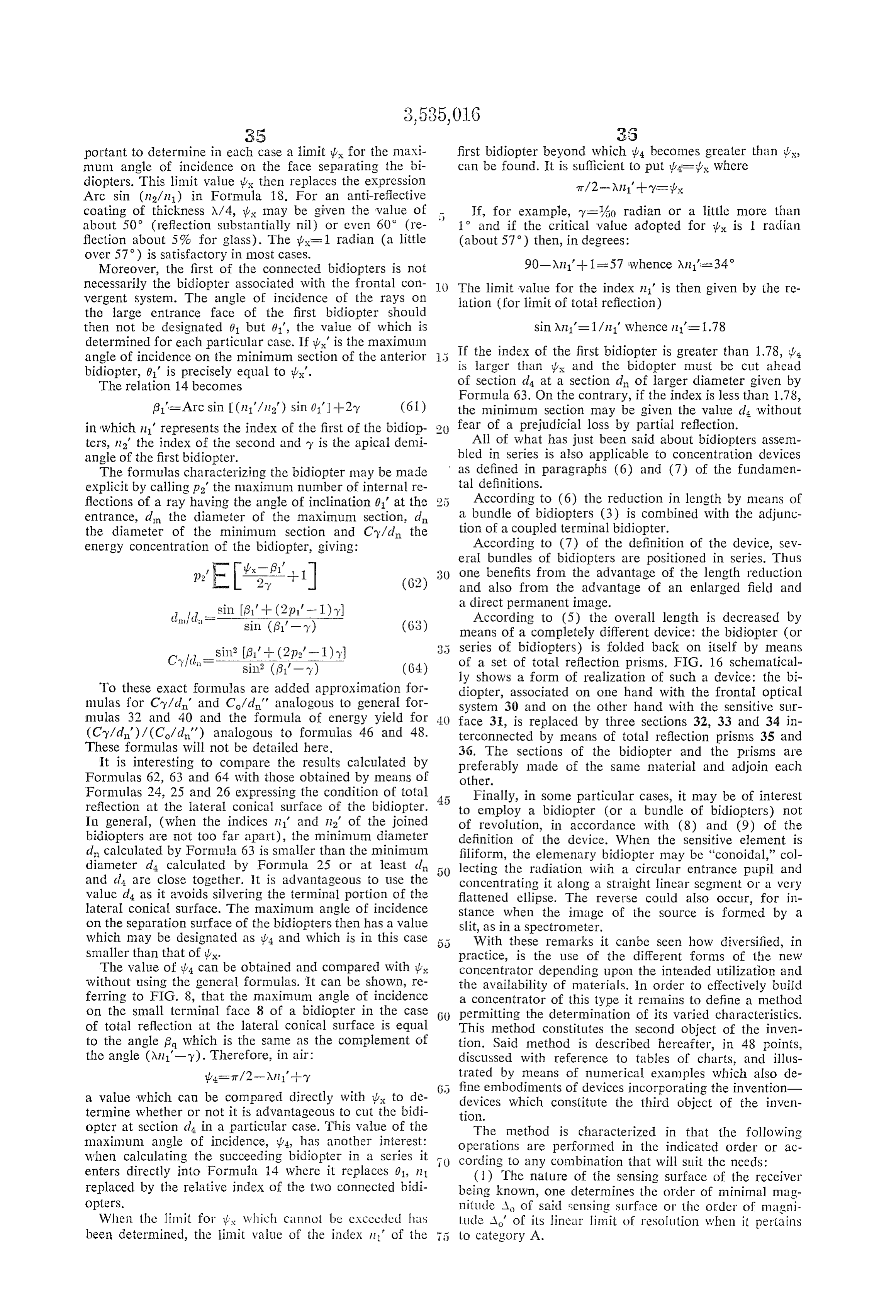
Page 27
(2) The value, preferably maximal, of index n of the (14) From it is deduced the value e1 of the diameter medium in optical contact with the sensing Surface is of the frontal image (or "ocular circle') : determined according to the experimental conditions which are available.
(3) The valve 1/N of the relative opening (or its (15) In the case of a concentrator of the direct perma equivalent) of the frontal concentration system is fixed nent image type, one figures out the total number W' (at as large as possible depending upon cost and suitable the diameter) of bidiopters associated with the sensing optical characteristics. Surface:
(4) The total energizing concentration C which must be required of the bidiopter or elementary frustioconical O wherein W=1 when d-A.
mirror (or from the combinations of bidiopters, mirrors The order of magnitude of the minimal diameter of or bundles positioned in series) is calculated as follows: the beam associated with the sensitive surface is equal
(5) The value of the resolving power e or field angle The diameter of the total sensing surface receiving the of the elementary bidiopter is determined as a function of image is equal to WA/W.
o, the apparent diameter of the Smallest Sources of a (16) In the case of a scanning concentrator, the char radiation flux which one desires to concentrate at an acteristics of the scanning are determined: frequency, average distance of utilization: average duration of coincidence of each image element
with the large flux receiving face of the elementary bi
(6) An upper limit, fmax, is fixed for the focal length (17). One fixes the minimum H of energy yield for the of the frontal concentrator System. entire assembly of bidiopters or frustoconical mirrors or (7) The upper limit, d max, of the diameter of the associated bundles.
large flux receiving face (associated with the frontal opti 25 (18) An order of maximal magnitude Limax is chosen cal system) of the elementary bidiopter is subsequently for the total length of the assembly of bidiopters or determined: bundles.
d maximaxXe (19) The order of magnitude of index factor n of the bidiopter (or of the bundle) associated with the sensing (8) do max, the corresponding upper limit for the surface is calculated as a function of the materials avail schematic value d of the diameter of the minimal Sec able.
tion (associated with the sensing surface) of the elemen (20) Graphs or tables are prepared each one indicating tary bidiopter, is calculated: for a given value of the ration1/n a great number of com binations between the values of:
(9) Value doma is compared with the minimal value 35 ?y, the half-angle at the apex of a bidiopter. of A as determined in (1) in the case where the sensing Co the desired energy concentration required of Said bi surface belongs to category A. diopter.
If do max) A, the order of magnitude of do, preferably m, the true energy efficiency.
minimal, is fixed: Lo, the length of the schematic bidiopter. For simplifica
40 tion this length is expressed with do taken as the unit.
If d mas.<Ao, one fixes the minimal number w (on (21) It is determined whether the order of maximal the diameter) of bidiopters of the elementary bean magnitude of length Limax chosen at (18) is compatible which must be associated with the Sensing Surface: with the values of C and H previously fixed. One begins by expressing Lima, taking as a unit the order of magnitude wasAo/do max of do fixed at (9) or at (10) and one then consults the and tables that have been prepared to find if there is at least one value of y which offers an acceptable compromise be 7tw°4N at Al4 dmas. tween Ct. H and Limax/do.
(total minimal number of bidiopters). If such a value of y exists, only one elementary bi The order of magnitude of do is then fixed: diopter (or bundle) may suffice.
The true order of magnitude of this elementary bi diopter (or of this bundle) can be chosen smaller than (contingent on do being greater than or equal to the Limax if the combinations offered by the tables are many. linear limit of resolution Ao fixed in (1)). If no such value y exists and in the case the sensing sur (10). In the event the sensitive surface belongs to cate 5 5 face belongs to category A, it is necessary to give do a gory B, the order of magnitude of do is nevertheless value smaller than the order of magnitude previously chosen so that chosen so that the ratio Lima/do has a value compatible, do-Ao in the tables, with C and H. The final value of d is sub sequently fixed and the value of the number (at the diam
If d mas.<A, means, such as total reflection prisms, 60 eter) of elementary bidiopters associated with the sensing are provided to shorten the overall length which is de surface is readjusted; W= A/do. termined by the focal length f. Or, if this is not possible, In the event the sensing Surface belongs to category B, one increases the relative opening 1/N of the frontal it is necessary either to decrease the values of C or of H, optical system in order to decrease the value Ct and final or to decide upon devices comprising total reflection prisms ly increase the value of do max (to bring it closer to the so as to decrease the overall length of Limax. value of Ao). (22) One fixes the number of bidiopters (or bundles) (11) The final value of focal length f of the frontal to be coupled in series by determining if the order of optical system is determined by adjusting fmax to the magnitude of length Limax (or of true length considered results obtained at (9) and (10). at 21), is compatible with the technology and the cost of (12) The diameter 2R of effective opening of the the materials available.
frontal optical system is calculated: (23) If only one bidiopter or frustoconical mirror is used (or only one bundle) the optimal parameters are determined by referring directly to paragraphs 37 to 46 (13) The value of the angle of total field T of the of the present procedure, proper consideration being also concentrator system is fixed. given to paragraph 26.
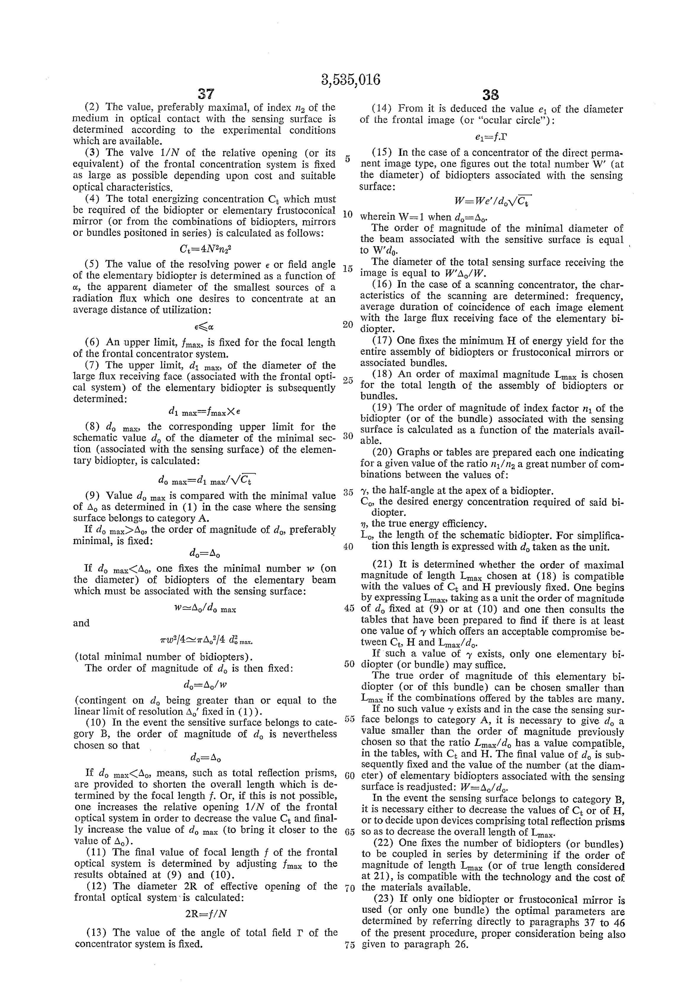
Page 28
(24) If several bidiopters (or bundles) are used in characterized by the upper limit as determined in 27) is series, generally two of them, the order of magnitude of calculated:
their respective energy yields m and n' are determined so Co=C/C that m me H (37) One fixes the final and optimal value of n, index 3 of the terminal bidiopter (the order of magnitude of which (25) Proper consideration being given to the technology has been determined at 19) taking into consideration the of materials, the cost, and the order of magnitude of do, best energy efficiency that may be obtained depending it is determined between which limits it is suitable to locate upon the values of the n1/n ratio. the optimal value of length Lo of the terminal Schematic (38) The optimal value of y, the apical demi-angle of elementary bidiopter (associated with the Sensing Surface). the terminal elementary bidiopter is determined by con Two limit values are chosen, an upper and a lower value, Sulting the charts of (20) and as a function of the values and are expressed choosing do as a unit. chosen above for Co., m and L. (26) One establishes the order of magnitude of the (39) One proceeds with the verification of the previous average length of travel of a ray inside Said terminal bi ly obtained findings by comparison with one another and, diopter and it is determined if the proportion of radia if need be, some of the values may then be readjusted. tion flux which is lost by absorption during Such travel is (40) The frontal concentrator system is constructed, compatible with the minimum energy yield in as defined characterized by an useful opening radius R and a focal in (24). length f which results in allowing the measurement of its Such evaluation is performed by calculation similar to other characteristics.
the one previously developed in the preamble of the (41) One proceeds with the accurate determination, by present procedure, consideration being taken of the tem Special calculation depending upon each particular case or perature of the bidiopter while in operation. by accurate measurement performed on the frontal con If the loss by absorption is negligible with regard to centrator System, of the value of sin 61, the order of mag the efficiency (as in most cases) the first evaluation of Lo 2 5 nitude of which is 1/2N (an approximation which is gen is kept. When it is not so (special situations) lower values erally satisfactory when the frontal system is aplanatic). of L are chosen. (42) The final value of diameter d is fixed, the di (27) An upper limit Co max is chosen relating to the ameter of the large radiation receiving face of the frontal theoretical concentration expected from the terminal bi elementary bidiopter (associated with the frontal optical diopter (or from the bundle) by looking through the system) the upper limit of which had been calculated tables of 20 for the greatest value of C, to which cor at 7, as a function of the true value (or measurement) responds a pair of values m and Lo compatible with the of focal length f (determined in 11), and measurable previous results. The corresponding Values of Y are at (40):
noted. d=fe (28) The lower limit Ci is then deduced relating to 5 the theoretical concentration Co expected from the front (43) One determines the value of the minimal diam bidiopter (or from the bundle) associated with the frontal eter d" of the frontal elementary bidiopter by means of optical system: Formula 19 in general cases or (25) in the case of a Sec tion of category d or else (63). One may also be satisfied
Co mini-C/Co X with the excellent approximation provided by Formula (29) The minimal value 1'1 mi of factor in 1 of the front () 31 in general cases or Formula 35 in the case of a minimal bidiopter is then calculated as follows: Section d4. To use basic Formula 14 0 is replaced by lx, the maximum angle of incidence on the minimum sec
Comin n. on-y 4N2 tion of the frontal bidiopter, and 111 by the relative index of the two coupled bidiopters.
(30) It is determined if the minimal section of this 45 (44) One calculates the value of length L'y, of the front bidiopter belongs to category d. (conditions of total frontal elementary bidiopter, by means of general Equa tion 28.
reflection) ord (general case) or d (conditions related to (45) d, the minimal diameter of the terminal elemen angle il depending upon the special data concerning partial tary bidiopter is calculated by means of the proper Equa reections). The optimal value of it' is then chosen. For tions 19, 15, 22 or 25 or one of the approximation Equa example in the case of section d4: tions 31 or 35. To characterize d, diameter of the large
1s winnin -- i. face of radiation collection of this bidiopter, one chooses (31) The final value of n' is subsequently chosen de the value found at (43) for the minimal diameter of the pending upon the availability of materials, their cost. frontal elementary bidiopter.
(32) The final value of C's, the concentration required tary(46)bidiopter 55 The value of length Ly of the terminal elemen is calculated by means of general For of the front bidiopter is then calculated. For instance, in mula 28.
the case of Section d: (47) From the values calculated above one determines the characteristics of bundles of elementary bidiopters, (33) The upper limit Lo as of the schematic length GO coupled in Series or not, the general structures of which of the front bidiopter is made explicit: were outlined in (9), (15) and (35).
(48) Depending upon the intended utilization and the cost it is decided whether two identical concentrators are and Lomax is expressed taking do as a unit (Limax has been to be placed "in parallel” to act simultaneously on both fixed at 18); L evaluated in (25) and (26)). (5.5 faces of the sensing element.
(34) The optimal value of y', the apical demi-angle of Understanding this procedure necessitates a few re the front didiopter is chosen by consulting the charts of marks.
(20) as a function of the values previously fixed for Co. From (1) to (10) there are set down the values of a n' and Lomax. few basic dimensions and the imperative and generally (35) In the event no value found in the charts is suit () conflicting data are adjusted, data provided on one hand able for y', the bidiopter is replaced by a bundle or a by the minimal value A of the diameter of the sensing third bidiopter is calculated according to the procedure Surface and on the other hand by the maximum value that from (28) to (34). may be assigned to the focal length f of the frontal optical (36) The final value of the theoretical concentration C system. This problem being settled as well as whether the required of the last bidiopter (which until now Was Only 5 sensing Surface belongs to category A. Or to category B,
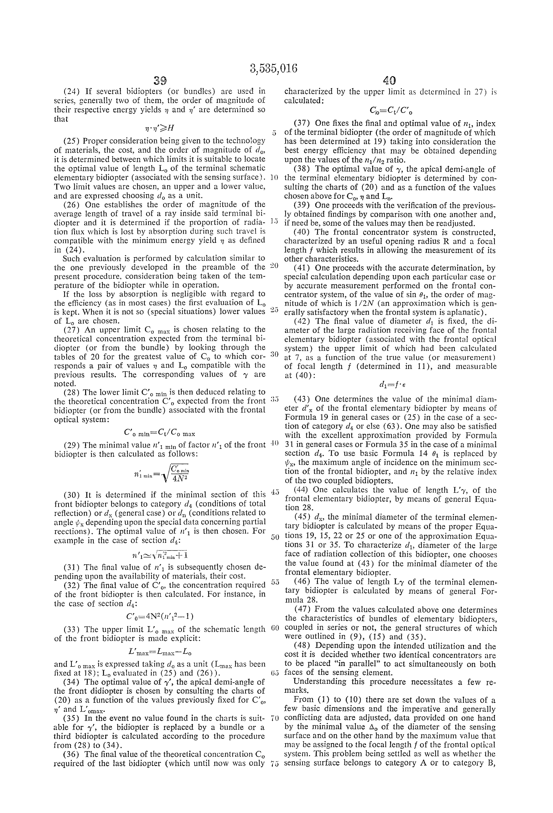
Page 29
the general arrangements of the concentrator are the The most complete approach includes preparing a object of evaluation and complementary determination in chart presenting 10 entries, choosing the minimal schem paragraphs (11) to (18). Then the characteristics per se atic diameter do as a unit for evaluating the other dimen of the elementary bidiopter are defined by a series of sions (f, di, Lo).
approximations. Most of the time it is necessary to couple 5 One can also prepare tables. The most useful type of in series two elementary bidiopters or two elementary tables is prepared as follows: for a given value of ratio bundles. First, and according to points (19) to (27), n1/n (which enters into the choice of the formula giving orders of magnitude and limit values are selected for the the energy efficiencies) the values of m and of Lo are de terminal elementary bidiopter (or bundle). Further, ac termined as functions of y and of Co. do is chosen as a unit cording to points (28) to (35) the structures of the frontal O for evaluating Lo. Three examples of such tables are pre bidiopter (or bundle) are determined. Then, at points sented hereafter:
(36) to (38), the determination of the characteristics of TABLE I the terminal bidiopter is effected and the procedure is com 111= n (complete immersion) pleted by the final calculations based on the lengthy ac curate equations relating to frustoconical bidiopters of maximum concentration (or their approximations).
In practice, as can be verified, the sequence of opera "(I-VC. 1.)
FIRST PART OF TABLE
For: concentration
Preliminary ni=n=3 of:
(For terminal bidiopters) Fi F|1.3
Co 94 3 4 9 16 32 36 64 - n 0.809 0.77 0.73 0.61 0.52 0.41 0.40 0.31 v=340 rad.---2, 2.5 3.7 5 O 15 23 25 35 do
5 7.3 0 20 30 46 50 70 do
7.5 11 15 30 45 70 75 105 do
2.5 18 25 50 75 116 25 175 do
25 37 50 100 150 233 250 350 do
250 370 500 1,000 1,500 2,328 2,500 3,500 do
tions constituting the procedure cannot develop auto The first part of Table I concerns principally the ter matically. The problem is itself too complex and it is 35 minal bidiopters (a primary concentration having been necessary to perform successive readjustments of which effected by prior bidiopters).
SECONO PART OE TABLE
If:m1 = m2=3 (for example), preliminary frontal concentration:
F/1.4 F12 F12.8 F14 F/5.6 Co 72 8. 144 256 288 324 576. 1, 152
37 40 55 75 80 85 115 i.70 do
74 80 110 150 160 170 230 340 do
11 120 65 225 240 255 345 510 do
185 200 275 375 400 425 575 850 do
374 400 550 750 800 805 1,150 1,700 do
3,740 4,000 5,500 7,500 8,000 8,500 11, 500 17,000 do
the efficacious and logical order has been indicated. This TABLE II is why a large number of steps of the procedure concern 55 m2 =3; n.1=4 (principally for terminal bidiopters) the determination of orders of magnitude. This is also why there is specified at (20) the preparation of a chart and tables, examples of which will be furnished hereafter.
There are eleven parameters involved in the simple as n = -—eith a schematic ele- 60
Sociation of. a frontal concentrator with 1- / Co. 2. -1 tan ?y mentary bidiopter: 722
Co 9.4 3 4. 9 6 32 64 - 0.860 0.81 0.76 0.60 0.51 0.39 0.28 Y=340 rad.---------- (2. 2.5 3.7 5 0 15 23 35 do = 2 0.922 0.894 0.86 0.76 0.68 0.57 0.46 Y%0--------------(3, 5 7.3 10 20 30 46 70 do - 0.946 0.926 0.90 0.82 0.76 0.68 0.57 Y-%0--------------(i. 7.5 1. 15 30 45 70 105 do l1 m O. 966 0.95 0.94 0.89 0.84 0.78 0.72 Y%0-------------- Lo 2.5 18 25 50 75 16 175 do - 0.983 0.977 0,968 0,945 0.920 0.881 0,832 Y-100------------- (L. 25 37 50 100 150 233 350 do - m 0,998 0.9976 0.9968 0.994 0.991s. 0.987 0.981 Y=yfo00-------------(i. 250 370 500 1,000 1,500 2,328 3,500 do
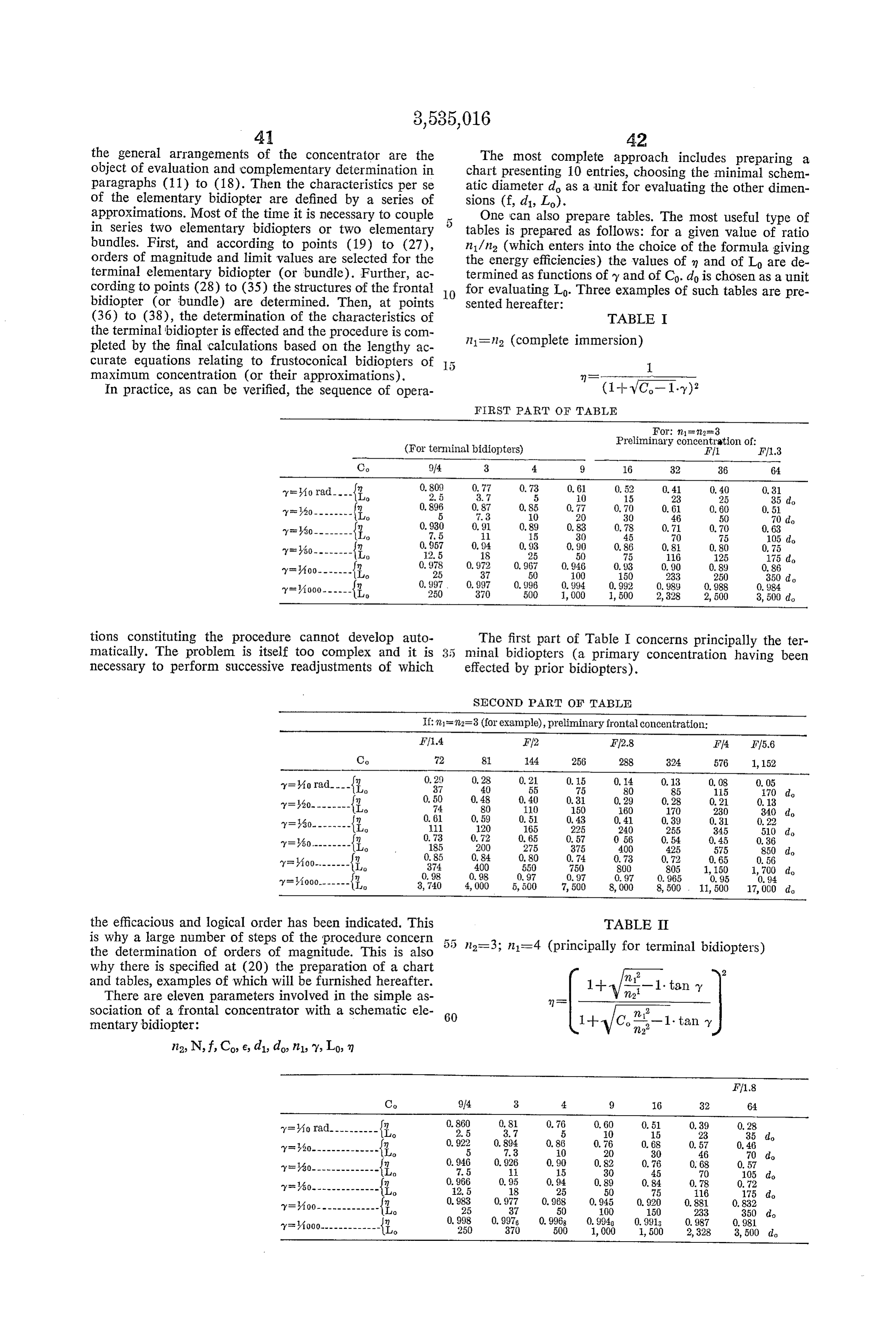
Page 30
TABLE III In addition to those heretofore given other types of tables are useful. More specifically tables prepared each n2=1 (sensing surface immersed in air) for a given angle of elementary field e, indicating, as func n=1.5 (bidiopter of ordinary glass) tions of varied values of n2 and N, the values of the total
RELATIVE APERTURES OF FRONTAL CONCENTRATOR
F/1 F/1.4 F12 F/2.8 Fi4 FI5.6
Co 4. 8 6 32 64 128 4. v. 0.66 0. 548 0.432 0.32 0.22 0.15 1=}?o rad.----, 5 15 23 35 52 do - (i. (). S03 0.71 0, 623 0. 506 0.40s 0.30
Y20- - - - - - - - Lo 10 18 30 46 70 104 do - 1.4 0, 865 0.792 0.71 0, 627 0.526 0.42
Y30- - - - - - - - luo 15 27 45 70 105 156 do
Y/50- - - - - - - - i. 25 46 75 16 15 258 do n (), 955 0.92 0.89 0.857 0.805 0.738 y100. - - - - - - Lo 50 92 150 233 350 516 do m 0.996 0.99 0.99 0.98 0.97s 0.968
Y=1000------ Lo 500 9,140 1,500 2,328 3,500 5, 160 do
The method of using these tables is obvious. The theore theoretical concentration C and of the focal length f of tical concentration Co. being fixed, the energy efficienciesthe frontal optical system. (f will be calculated using as and the lengths for different given values of the apical 25 a unit do, diameter of the schematic elementary bidiopter, demiangle of the cone are compared at a glance. It should which permits finding at a glance the order of magnitude be understood that the tables presented here as examples to be considered for domax of step (8) of the procedure.) are far from being complete enough to answer the actual Two examples of such tables are offered hereinafter and needs of the engineer charged with producing frustoconi will be used for numerical illustrations. cal bidiopters according to the invention. Very detailed 80 Table IVuseful is prepared for e=Aoo radian and will be tables should be prepared wherein the Successive values of especially for solar concentrators. Table V is pre pared for e=4000 radian (resolving power comparable to angley would differ by 10' and those of indices 112 and 11 the would differ by tenths (or less). Tables should also be tableshuman eye during full daylight). In each of these prepared for the case of the condition of total reflection and a there has been presented for a given value of In given value of F/N the corresponding values of (section d, point (2) of the fundamental definition) and 3 the efficiency in be determined by means of equation (47). Ct and f.
TABLE IV
frt,
e = 1/100 radian N2 1. 2 4 8 1G (34) m;2 FIN F1 F1.4 F12 Ff2.8 FF4
70- 1.5-------- 2.25 3. t 300 424 600 848 1,200 do
2=2.25 5 (9t 20 40 80 160 320
n=2.5-------- 0.25 500 707 1,000 1,414 2,000 do 22: 9 (?: 36 72 144 288 576 2- -- - - - - - - - {t egg 848 1, s 1,697 2,400 do - 98 19 392 784 722-3.5-------- 12, 25 : 700 989 400 1,980 2,800 do 122-4 16 $9t 64 128 256 512 1,024 2- - - - - - - - - - f 800 1, 131 1,600 2,263 3, 200 do
TABLE V
e = 1/1000 radian N2 1. 2 4 8 G (34) n2 FIN F/1 F/1.4 F/2 F/2.8 F/4 2, it 1. { Ct 4. 8 6 32 64
- --- - -- -- fCt 2,0g9 2 s;18 4, 936 5g
722-2.5-------- 2.25 { 3,000 4, 240 6,000 8,480 12,000 do insic2 A 9t 16 32 64. 28 256 2 A..... - - - - - - - - f 4,000 5, 660 8,000 11,300 16,000 do 22-2.25 5 * 20 40 80 160 320 - -Wu - - - - - - - f 4,470 6,320 8, 940 12, 650 17,890 do 129 -2 6.25 't 25 50 00 200 400 24.0- - - - - - - - 20 if 5,000 7,070 10,000 14, 140 20,000 do, ls, 3 9 $2. 36 72 144 288 576 2"- - - - w - - - - - - {lit 6,099 8, 18;
22-3.5-------- 2.25 {f 7,000 9,890 14,000 19, S00 28, 000 do i-l 15 f(3t (l 128 256 512 1,024 ltg:- - - - - - - - - - - if 8,000 11,390 16, ()()() 22, 13t) 32, ()(?) do
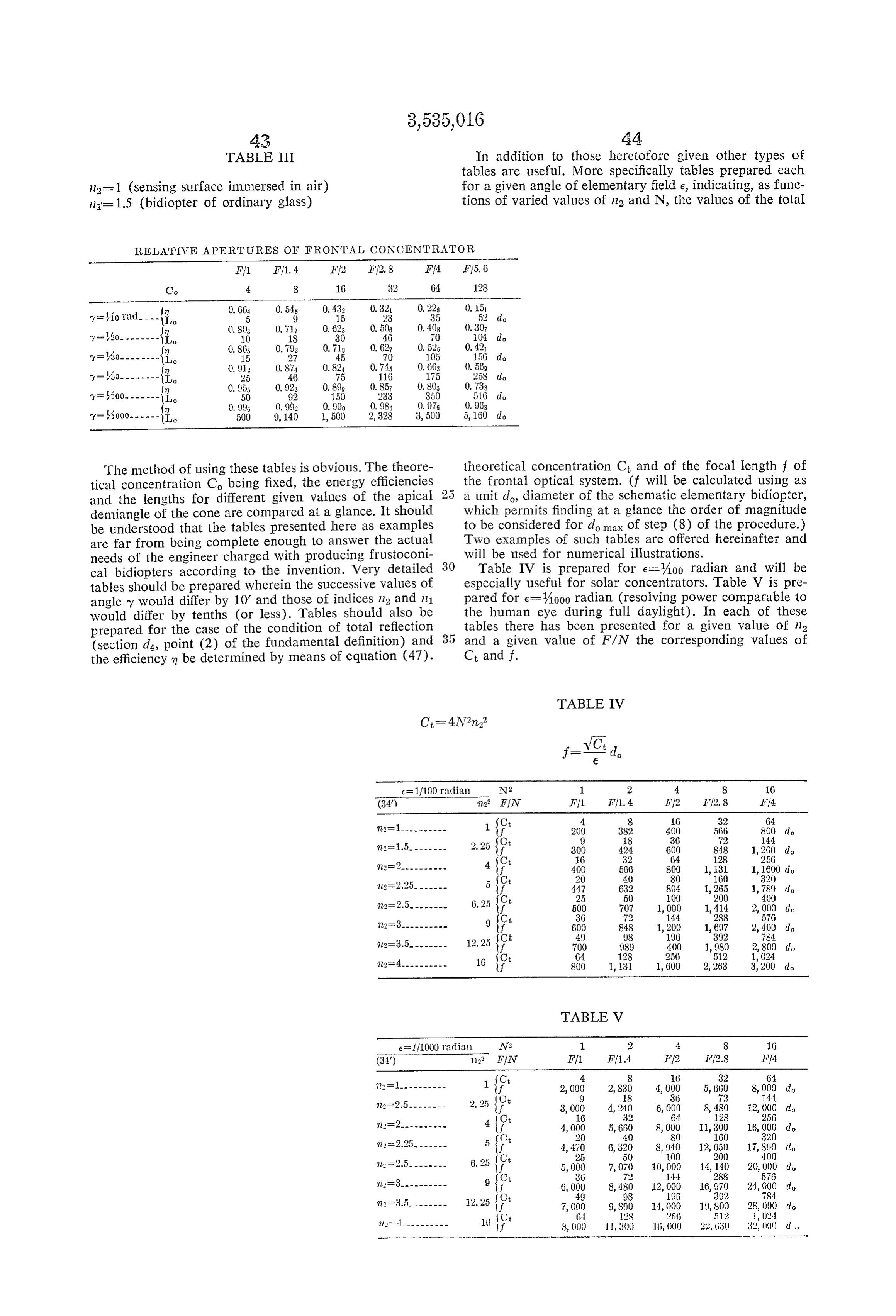
Page 31
Two distinct tables have been prepared for e=400 average optical path to 1 mm. in a very short terminal radian and for e=A000 radian so as to make their con bidiopter made of tellurium, it is possible to obtain a Sulation easier while proceeding with numerical applica concentration about twice as great as with germanium. tions. However, as the values of C are the same whatever This is realizable by having such a terminal tellurium e may be, it is possible to combine several of these tables bidiopter preceded by a coupled bidiopter of germanium. providing f with as many entries as we have values re 5 The concentration C required from the terminal bidiopter lating to e. The evaluations of f as a function of do have is slightly greater than 2.5 (be it taken into consideration been presented in round figures; only the order of magni that it is preferable to end the minimal section of the tude of these figures need be used. germanium bidiopter at d4, and that the maximal inci Several refinements concerning the practical method dence angle it must be controlled). Table indicates of using these tables will appear when numerical examples 10 that for so small a value of Co an apical demi-angle y of are developed. 40 radian allows an efficiency of almost 90% for a A few other points of the procedure call for special Schematic length Lo equal to only 5 times the minimum commentS.
While figuring the lower limit of energy efficiency H schematic diameter d. With d-0.1 mm. we therefore obtain a small at point (17), or of n and m' at point (24) consideration The maximum optical path schematic frustum of a cone 0.5 mm. long. should be given to intersticial losses in the bundles of z, defined above, will not reach 1 mm.
bidiopters being considered. The efficiency of a bundle This possibility will be again found in the examples of is obtained by multiplying the efficiency of one of its numerical bidiopters by 0.785 or by a factor comprised between 0.7 20 benefit fromapplications.
this
It should be understood that to exceptional maximum concentration it and 0.6 if the bidiopters are sheathed. has to be possible to immerse the sensing surface in the Point (26) further requires clarification. Calculation small face of the tellurium bidiopter. This is feasible in of the efficiency loss by absorption in a bidiopter is not a the case, for instance, of a phosphorographic powder for simple matter. An excessive order of magnitude can be a metascope.
obtained by considering the ray traveling the longest path of a thermistorIt isfornota possible in the case, for instance, bolometer because tellurium is a inside the bidiopter. Such ray is one of these entering at semi-conductor. It is then necessary (in the present state the margin of the large surface of radiation entrance and of the art), as it is for germanium and silicon, to isolate presenting the maximal incline 01 relatively to the optical the thermistor with a thin layer of selenium arsenide for axis. It is determined that its length is fixed by the relation instance, the index of which is lower than 3, which makes d this type of application unattractive.
2 LY2 tan y These remarks about the procedure will be terminated by specifying the conditions for choosing index n1 at
It is also known that any optical material transparent steps (19) and (37). The value of the ratio 111/n is to radiation of a given wave length is characterized by a involved in the calculation of the energy yield in as was constant factor k which is optical density per unit of thick previously seen. By comparing Tables I and II it can be ness. If a thickness x of such material is traversed by the seen that for any given value of y the efficiencies of Table radiation, the ratio d/d of transmitted flux fix (after I are better when Co is at least equal to or greater travel x) to original flux do is the factor of internal trans than 9; on the contrary, they are not as good as those mission T.: of Table II when C is smaller than 9. This dividing line 40 located here (for n1/n 2=4/3 compared to n1/n 2=1)
and at C=9, also varies with the value of n1/n. When r= 10-kx n1/m2=3/2, compared to n1/n2=1, it is located at about
C=3. Thus the greater the variation between index n1
It is therefore possible to know the proportion of pre of the bidiopter and n2, the index of immersion of the served flux and the proportion of absorbed flux in a sensing surface, the more often it is desirable to immerse bidiopter after a maximum traverse in the order of z. The 45 this sensing surface in the bidiopter itself. The difference loss by absorption is thus largely over-estimated when of efficiency may be important. For instance, with n=4 compared to the true average loss. and n2=2, we have, for C-144 and y=A00 radian, However, in most cases this loss, even if over-estimated, an efficiency in which is equal to 0.67. With n1=n=2 remains small. Good materials indeed have an optical : (immersion) we have, under the same conditions, density k per unit of length which is very small; for in m=0.80, which represents a gain of 13%. Therefore the stance close to 104cm. for a good glass (in the visible problem should be considered in each special case be range) and even less for germanium and silicon of great fore choosing the material composing the terminal bi purity (in the infrared). When k=104cm. and the trav diopter.
erse is 100 cm., we have t=0.9772 and a loss of 2.2%. 55 A few numerical examples (six) of concentrator cal However, in some cases, absorption can present a prob culation, accompanied by figures, will conclude the clari lem. On one hand, for materials such as germanium and fication of the procedure and will define embodiments of silicon, for instance, the factor k is only very Small when devices incorporating the invention.
the material is very pure which is not always the case. In the example of the design of a concentrator of infra On the other hand, germanium and silicon being still taken 60 red radiations (1 to 5u) for a laboratory receiver of the as examples, the factor k increases with the temperature. cell type or bolometer, each step of the procedure will It is therefore important in the practical application of be taken up seriatim:
point (26) of the procedure to specify the experimental (1) A receiver of infrared radiation of the cell type conditions existing while the concentration occurs So as or bolometer has a sensing surface of category B, that to determine the optimal value Lo accordingly. is to say, integrating all the radiation that is received There is finally the case of optical materials which are without point-by-point differentiation. In the cell type, relatively absorbent which can be considered for con the smallest sensing surfaces appear to be the photovoltaic stituting bidiopters according to the invention only by elements consisting of indium antimonide, the surface of limiting their use for very short bidiopters coupled with which is in the order of 0.03 mm.2. Thermistors for others made of very transparent materials. Tellurium is, bolometers have a smaller surface for instance in the O order in that respect, very interesting. It is very absorbent of 0.01 mm...?.
(about 20% loss, for a thickness of 1 mm. in the infra We fix here:
red) but its refractive index is very high (6.3). The Ao-0.2 mm. square of the index reaches about 40, 2.5 times more than (2) All materials the index of which is greater than with germanium (n=16). Therefore, if one limits the 75 3 for infrared radiations are semi-conductors. As it is
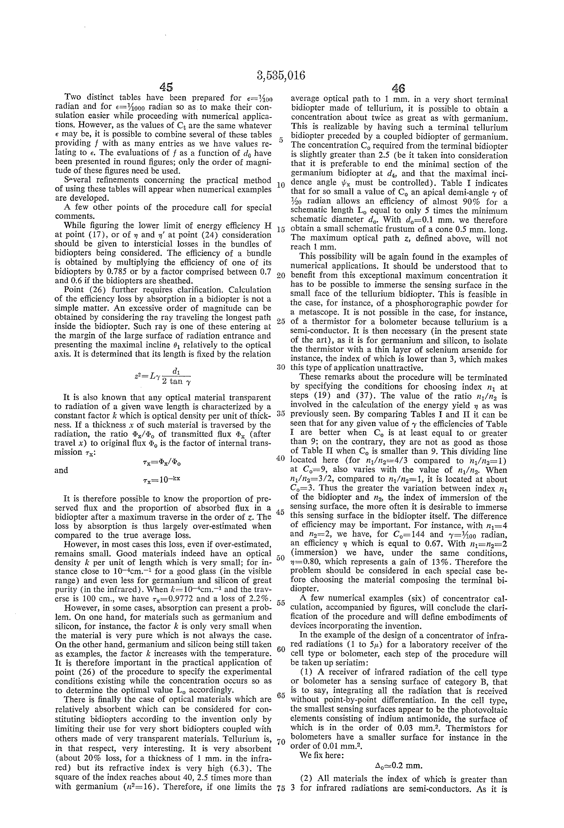
Page 32
then necessary to insulate the sensing element and as the which are close. In Table : y'-'Ao(), m=0.89, insulating material having the greatest index (near 3) Lo=250d.
is Selenium arsenide, we have (35) Not needed.
in 2-3 (maximal) (36) Co- 144/36= 4 (C and C are round numbers because the value 1.799 of n' varies only slightly from (3) Lens objective opening at F/2 (supposed given) 5 the theoretical value 1.80).
N-2. (37) in 1=3.43 (silicon is perfectly suitable). (38) There is a choice in Table I between y=1/30,
The first combination can be used. The efficiency is (5) We can here verify the distance from the source O Sufficient.
and, subsequently, its apparent diameter. We fix: The schematic length equals 3 mm. (39) A total efficiency greater than 0.75 is obtained e=Ao radian (543°46’) m m'- 0.89 x 0.89-0.79 (6) finax=50 mm. (supposed given). (40) and (41) It is assumed that the frontal converging (7) d max=5 mm. System is aplanatic and
(9) Not needed. sin 0=1/4 (10) do=Ao=0.2 mm. (since do max) Ao). (42) d=fess2.4 mm.
(11) f=fmaxx0.2/0.42=24 mm. (43) The minimum section of the frontal bidiopter be (12) 2R=12 mm. longs to category d'4. Its diameter is therefore obtained (13) In this particular instance, T-e=A radian. accurately by applying Equation 25 and Equation 35 pro (14) (15) (16) Purposeless here. vides an excellent approximation. By using the latter to (17) H20.75 (supposed given). gether with Equation 14 we find that (18) Limax=100 mm. (Supposed given).
(19) To prevent having to resort to silvering the ter minal portion of the elementary bidiopter it is preferable As the values of the theoretical concentration C (-36) to provide for the termination of said bidiopter at sec and of the energy yield n’ (= 0.89) are known the value of tion d4. As ne=3, the minimum value of index n of diameter da can be calculated more rapidly. Because the the terminal bidiopter is true ratio di/d'4 is equal to V36 multiplied by V0.89 or nev}-1 that is, 3.16 6X0.94=5.65
Many optical materials are transparents from 1 to 5 So that also having a mean index greater than 3.16. One of the d=2.4/5.65-0.43 most common is silicon (index 3.43 for 3p). (44) According to Equation 28 the length L., of the (20) See tables. frontal bidiopter is 99.97, or, choosing the closest round (21) Limax=500d. Table l is used as the conditions value are near those of immersion in the bidiopter, L=100 mm.
There is a value of y which is perfectly suitable. For ?y-Aoo and C-144 we have H = 0.80 and L-550d. 40 (45) By the quick procedure with C-4 and n=0.89: Only one elementary bidiopter will suffice (it is not d'Ad=2x0.94=1.88 necessary to resort to a bundle). So that (22) On the other hand, it is not desirable to have d=0.23 mm.
the elementary bidiopter (the length of which may reach 100 mm.) made only of one material such as silicon. To use Equations 31 and 14 one would have had to re (23) Not needed. place the maximum angle of incidence 01 at the entrance (24) n=-V0.75 (less than 0.87). by the maximum angle la calculated by means of the fol (25) 2.3Lo<5 mm. or lowing equation (already encountered):
(26) No problem of absorption.
(27) From Table I: Co make 4 (two sets of values are (46) Calculation provides:
suitable: Ly=3.036
m=0.89 and L=15d for y=4.0 radian and Ly=3.04
(28) Comin-144/4=36 55 (47) Not needed.
(48) The cell for infrared radiation or the labora (29) n' in-V36/16=1.5 tory bolometer constituting this first example of numerical (30) In the case of section da (condition of non-silver application may advantageously comprise two devices ac ing) cording to the invention disposed in parallel. n'=v2.25-1-1 =1.80 60 FIG. 17 shows the optical part of a bolometer having Furthermore, assuming that the limit of the angle of an immersed thermistor, the characteristics of which are incidence is after anti-reflection treatment of the surfaces those just calculated. This bolometer comprises two spheri is 1 radian it has been seen that the index of the bidiopter cal diopters for flux entrance, 37 and 38, the optical axes should not be too much greater than 1.78. It is therefore 39 and 40 of which converge in the direction of the infra desirable in the present circumstances to cut the bidiopter red radiation source assumed to be located at a known at section d and to choose an optical material with an distance. The index of these diopters equals 1.8. The en index close as possible to 1.80. trance surfaces 41 and 42 coated with an anti-reflection (31) Such material exists. Glass VIR-3 containing layer are characterized by an aperture diameter of 12 germanium oxide (manufactured by Societe Sovirel, Par mm. and a radius of curvature of 19.2 mm. The optical ra-Mantois Department) is characterized by the following axes of totally reflecting faces 43 and 44, cut at an angle limits of transmission: 0.3 to 5.5u, and by an index of of inclination of about 44, coincide at 45. These frontal refraction of 1.799 for A-3g. diopters form images of the source respectively at 46 and (32) C-16X2.24-35.85-36. 47. The associated frontal bidiopters 48 and 49 measure (33) "as 100-52295 min). e-475d. 2.4 mm. at the diameter of the large faces, 100 mm. in (34) For C=36, Tables I and Il Supply values of m' ) length and 0.43 mm. at the diameter of the small faces
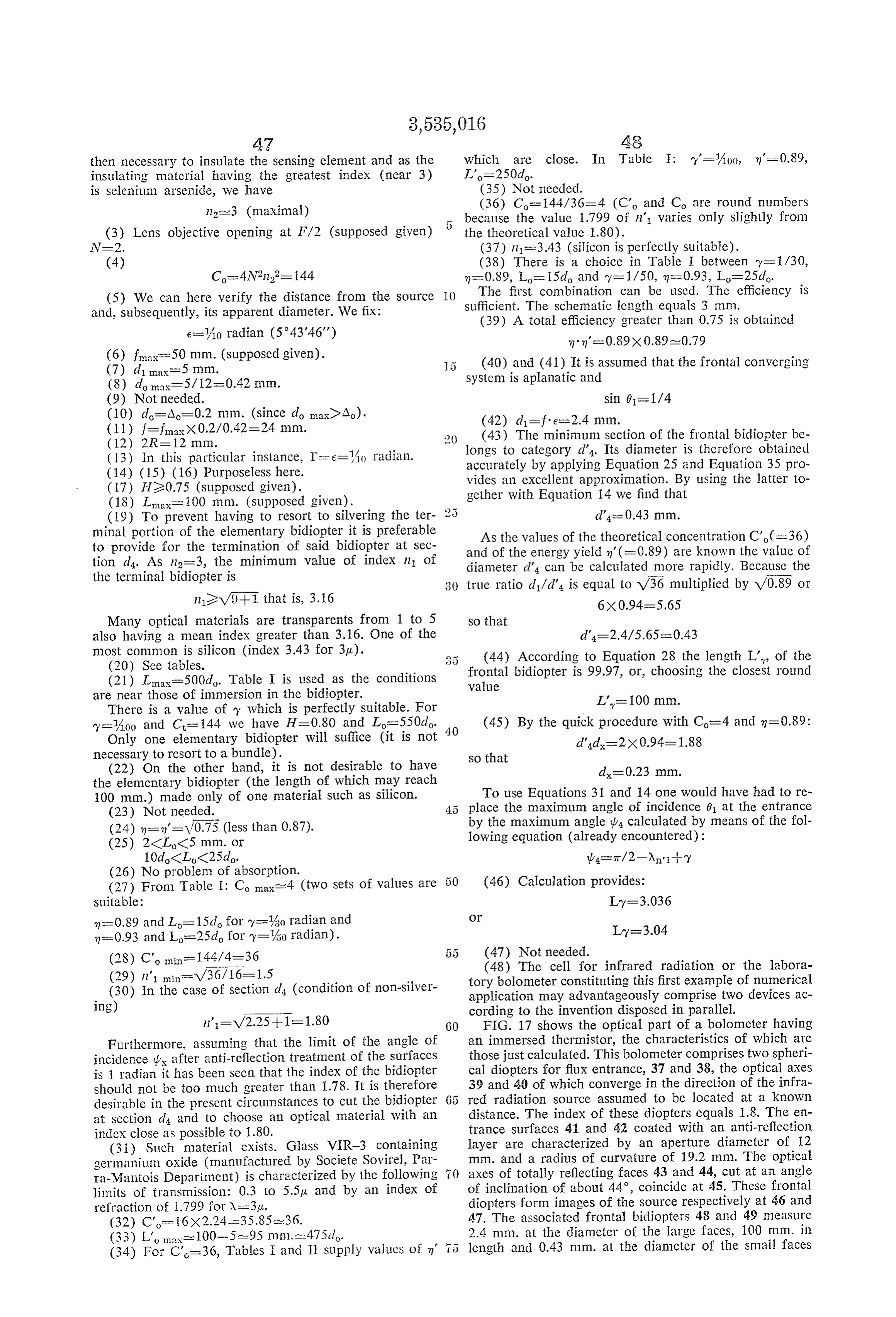
Page 33
(50, 51 on the figure). The terminal bidiopters 52 and It follows that the focal length of the parabolic mirror 53 of silicon (appearing in black on the drawing) are 3.04 is f=1.41 cm.
mm. long and the diameter of the small terminal faces The diameter of the mirror is 2R-100 cm. (54, 55) is 0.23 mm. The two small end faces coupled It remains to determine the optimum characteristics of respectively with the two faces of a semiconductor sensing 5 the frustoconical mirror 61. Table I offers for C=9 layer (thermistor) 56 and insulated from it by means (closest value to 8) a choice of values for the apical of thin films 57 and 58 (of selenium arsenide, for exam demi-angle y. The value y=Aio radian is excellent as it ple). The proportions of these terminal elements have permits an efficiency of 90% and requires a schematic been exaggerated in the drawings; actually the minimal length Lo of about 50do or 25 cm. sections 54 and 55 are extremely close to sensing tape 56. O Calculation results in d-1.41 cm. (already fixed); The latter is connected to the electrical components (not d=0.53 cm.
shown) of the bolometer. The diameter of the minimum section of the frusto The energizing concentration obtained by means of conical mirror 61 is here designated as dis because the util this bolometer according to the invention can be com ization occurs in air. Calculation results in d=0.526 and pared with the concentrations obtained by means of con the value of 0.53 is chosen for calculating Ly ventional bolometers. The energizing efficiency of the Ly=20.50 cm. coupled bidiopters is '-0.89 x 0.89-0.79 The large section d of the metallic frustoconical mir ror 61 is located in the focal plane of the parabolic mir
It may be assumed that the actual efficiency is in the ; ror (see FIG. 18). The end 59 of the dipole antenna is order of 0.70. The other losses of efficiency are the same located as close as possible to minimum section d and is in the bolometer of the invention as in the other bolome connected to the radar (or maser) assembly by means ters; they will not be considered in evaluating the com of wave guide tube 62.
parison. Such a wave detector is characterized by an efficiency With respect to a bolometer with immersed thermistor about 7 times greater (8x 0.9) than the efficiency pre having at the entrance a convergent system consisting of sented by a parabolic mirror such as 60, used above. a spherical diopter having the same characteristics as those The third numerical example relates to searching heads of diopters 37 and 38 described above, the energizing effi for detecting missiles by infra-red radiation. We will con ciency obtained with the new bolometer is: sider Successfully several conditions of utilization. 30 The angle e of the elementary field will first be chosen
that is, two hundred times greater.
equal to 4000 radian and the scanning field T of the searching head equal 30.
It is to be noted that bolometers of known designs are If the sensing element is of the B type (bolometer tape, most often equipped with entrance diopters of lesser or thermistor, or infra-red sensitive cell . . .) its minimum opening or presenting optical characteristics which are diameter A is about A0 or, at least A30 mm. Therefore not the most suitable (for instance, the sensing element long focal lengths will characterize the frontal optical is located at the geometric center of the spherical diopter, system.
which lessens the efficiency). In comparison to a frontal For instance, when Ao-0.1 mm. and n2=3 we have: system opening to F/3 for instance, the concentration 40 obtained with the bolometer according to the invention is
that is, four hundred fifty times greater. d=0.85 mm. In comparison with a bolometer having a simple The focal length f of the frontal optical system equals window with parallel faces as an entry optical system, the f=0.85X1.000=850 cm. resulting concentration, for a source of apparent angle O.
(Equation 10) is and its diameter 2R is equal to 607 mm. The device, even though it is cumbersome, is realizable by means of a parabolic mirror associated with a bidiop times greater which for a field of Ao radian amounts to a ter. For the latter we will have, for instance: concentration about 5,000 times greater. y=60 radian The second numerical example relates to a concentrator associated with an active detector of centimeter waves m=0.73 (“radar' or “maser' type). The main characteristics will L=185d=18.5 mm.
be given directly without going through each step of the 55 procedure and reference will be made to FIG. 18. The biodiopter may be simple or may consist of two The sensing element is here a dipole antenna 59, the biodiopters coupled in series, the first made of glass and useful minimum diameter of which is about 0.5 cm. the second made of a material having an index greater than 3.
A=0.5 cm. With a sensing element having a diameter equal to 40 60 mm. we obtain dimensions which are half as large:
This dipole antenna is located in air so that n2=1.
The frontal convergent system is a parabolic mirror 60, opening to F/1.4. d=A=0.05 mm. The associated concentrator according to the invention d=0.425 is here a frustoconical mirror 61 (n=1), of aluminum 65 for example, the desired theoretical concentration Co of L=9.3 mm. which is equal to: f=425
C=4X(1.4)2=8 2R=304 mm.
d=0.5 cm. 70 The frontal optical system may consist of a converging d=0.5x V8-v2=1.41 cm. lens system or of an afocal arrangement provided, if The field angle of the ultra-short wave scanning spot need be, with a prism device for reducing the overall di is about 30' or Aoo radian. Thus mensions.
If it is intended to further decrease all dimensions it is e=A00 radian 75 necessary to resort to a sensing element of category A
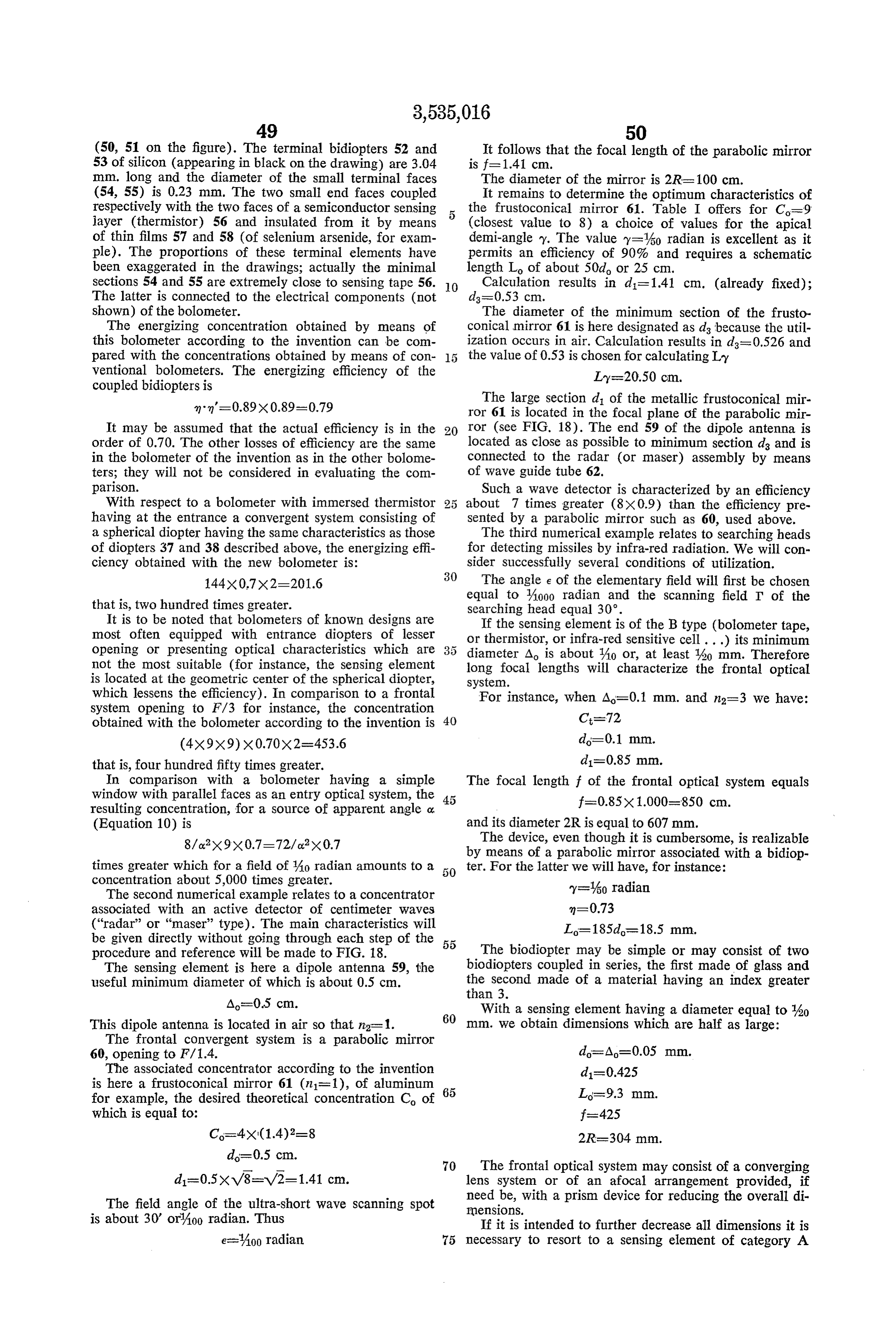
Page 34
associated with bundles of biodiopters. Two numerical which accelerates and focalizes the electrons transmitted examples are presented: by the sensing element.
The first relates to a searching head having a resolving A second example of realization (not shown in the power of A000 radian, a total field of 30, and a total drawings) extends the performance even further. length (without any prism) of about 1.5 cm. The main 5. The resolving power e is increased to 6000 radian (or characteristics are as follows, reference being made to 2 m. as seen from a distance of 10 km.). The total field FIG. 19. remains equal to 30'. The opening of the frontal con The sensing surface is a photocathode 63 the linear vergent objective is F/2.04. The theoretical concentration limit of resolution of which is about 10u and the useful Co now equals 100. The associated fiber bundle com diameter about 0.2 mm. This photocathode is immersed O prises 50 fibers per diameter (a little less than 2000 total) in the plane of the minimum section of a bundle 64 of the characteristics of which are, for each one of them: conical fibers made of special glass having a large index such as arsenic trisulphide glass (As2S3) or arsenic penta selenide glass (AsSes). The index of these glasses is com (this is a minimum, with respect to the wave lengths of prised between 2.4 and 2.7 for infra-red radiation. We the concentrated radiations) will take for calculation purpose: 712=2.45 so that in 2-6. d=80.u.
The frontal optical system 65 is a convergent objective y=A000 radian lens, opening to F/1.4. The concentration Co required of m=0.98 the fiber bundle consequently equals: Lo= 4,500 d=36 mm.
The minimum diameter d of each fiber is about 20g, so that, for each fiber: The elementary field e' of the bundle equals A00 radian. AS in the preceding example the total field (30°) is ex di-V48.20aa-1404 2 5 plored by Scanning (mechanical scanning or scanning of Since e=Aoon the focal length f and the opening diam the image). The exploration movement can be slow as eter 2R of the frontal objective are, respectively: the elementary field e' has a large value relative to the f=140 mm. total field. An automatic device can maintain the image 2Rs 100 mm. of the detected Source at the center of the sensing sur 3 O face and control the Scanning to keep the concentrator
The fiber bundle comprises 10 fibers per diameter aimed at the Source.
(which results in a total of about 78 fibers). The minimum Searching heads of this type, considerably more sen diameter of the bundle is therefore in the order of 200u, sitive and more accurate than the detectors presently which is also the order of magnitude of the useful diam known, make it possible to spot, at a great distance, eter of the photocathode. 3 5 any type of missile and trigger its interception. =0.2 mm. The fourth example relates to a phosphorescence tele Scope. (Not shown in the drawings as the schematic
The elementary field e' of the bundle equals 10 times illustration of it is substantially the same as in FIG. 19 the elmentary field of one fiber. reduced to parts 63, 64 and 65). e'=400 radian 4.O The resolving power e is A000 radian. The total field The schematic characteristics of each fiber of the bundle
are as follows:
The frontal optical system consists of a convergent do=20p. objective lens opening to F/2. A bundle of conical fibers
asSociated with this objective comprises 140 fibers per n=A00 radian 4. 5 diameter (that is, about 15,400 fibers total). These fibers
are made of Special glass for infrared radiations, the index of which is about 2.45.
Lo=300d=6 mm. The Sensing Surface consists of a very fine phosphoro The true characteristics are: graphic powder (that is to say a phosphorescent substance d=140u. initially excited by means of ultraviolet radiations having d=21.9p, the property of becoming luminescent when subsequent infrared illumination occurs) immersed in the plane of (using symbol d to designate the minimum diameter of minimum sections of the fibers. We have one fiber, the present case being a case of complete im mersion) or 55 n=2.45 da=22u. n=6
(in practice if the fibers are made of drawn glass, the meas The minimum diameter of each fiber is about lurement of Ly provides only an approximative value, the O accurate measurement of d and d only need be con do=25u. sidered).
The total field (T=30) of the device being about 20 d=245u. times greater than the elementary field (e'=JA00 radian) of So that with e=4000 radian the focal length f and the the bundle, a scanning movement is imparted to the search 6 5 opening diameter 2R of the frontal optical system will ing head so that it is capable of exploring the field in its respectively be:
entirety. On FIG. 19 has been shown the spiral 66 de f=245 mm. Scribed by the optical axis of the concentrator, said optical axis being caused to rotate around a fixed point located 2R=123 mm. in the vicinity of sensing element 63. For each fiber we have Scanning is realized by any known means. It is also possible to resort to an optical scanning of the image. y=4000 radian Photocathode 63 is incorporated with a phototrans m=0.98 nitting detector 67 (a vacuum cell of the silver-cesium layer type, or a gas cell, or a dynode photomultiplier) s Los 4,400d=110 mm.
Page 35
The bundle efficiency, consideration being taken of and the small terminal face has a diameter eo of about the intersticial losses and of the fiber sheathing, is about 0.3 mm. The elementary field e' of the bundle associated 60%. with the frontal optical system is 10 times greater than The phosphorescence telescope further comprises a the field of one fiber:
magnifying ocular (linear magnificationX 10 or X20) 5 allowing the observation of the image formed by the e'=4000 radian mosaic of the fiber minimum sections and revealed by An ocular 71 of linear magnification of X 15, permits the phosphorographic powder. The over-all length is observation of the elementary luminous signal appearing less than 40 cm. at the end 70 of the fiber bundle. The fifth example relates to a special metascope con O The total field I of the device is 20° (or about 0.35 ceived for detecting at distance small sources transmitting radian). The elementary field e' being equal to 0.01 radian, infrared radiation in a narrow and well defined frequency the apparatus is provided with a dual mechanical scanning band. device which allows a system exploration of its field of Taking into consideration the atmospheric spectral action. To achieve this (see FIG. 20) the metascope is transmission, this narrow band can be centered, for mounted on a horizontal platen 72 of tripod 73 by means instance, at about 1p, 1.5u, 2.1p, 3.7p, or 10u, because, of an annular element 74 in semi-tight frictional and in practice, for such wave lengths, atmospheric air offers pivotal engagement with platen 72. The latter is provided excellent transparency whereas around 2.5u, 6a, and 15u, with two levels for controlling the horizontality and is for instance, the transparency is practically non-existent. locked in position by means of a ball-and-socket joint A 10u wave length is particularly interesting in that it (accessories which are not shown in the drawing). The corresponds to an absolute black body temperature of observer can therefore impart to the metascope a slow about 310 K. It therefore corresponds to the natural horizontal exploratory movement by means of handles transmission characterizing the human body and not 75 and 76. The metascope is further supported, in a plane very warm objects (310 K. equals 37° C.).
The metascope according to the invention described 2 5 close to its center of gravity, by two brackets 77 and 78 gripping a third bracket 79 integral with the annular part herein is designed for detecting natural infrared trans 74. A pawl-and-ratchet device (not shown on the draw mission of sources having an apparent diameter greater ing) similar to the one cooperating with the rollers of a than Aooo radian ( 50 cm. at 500 m., or 1 m. at 1 km.). typewriter, provides for pivoting the metascope by means Its principal characteristics, reference being made to of knurled knob 80 in a vertical plane containing its opti FIG. 20, are as follows: 30 cal axis by small angular increments A000 radian). A lens objective 68, of relative aperture F/1.4, is The exploration movement is thus very efficient and associated with a bundle 69 of conical fibers made of easy to control. The elementary field e' of a bundle (Aoo glass which is transparent to the selected wave length. radian) being 10 times greater than the field e of a fiber In the case of a wave length in the vicinity of 10u it (4000 radian) one assumes that the luminous signal in is advantageous to use a glass containing Selenium and ;3 5 dicating the existence of a source remains visible long arsenic the curve of internal transmission of which shows enough while the slow scanning movement is taking place. a sudden drop toward zero between 12 and 13p (pro A selective filter may be added to the apparatus (located, viding a good selective function) and having an index of for example, in front of the large face of flux entry of 2.47 (for 10u). the fiber bundle) in order to allow detection in a very The sensing surface consists (as in the case of the 40 narrow band. For instance, in the case of detection at phosphorescence telescope) of a fine phosphorographic about 10p, by utilization of selenium-arsenic glass, it is powder immersed in the plane 70 of the minimum sec possible to limit the transmitted band to the interval 9 tions of the fibers. For some of the values of detected to 12pt, by adjoining a thin filter of indium antimonide wave lengths it may be difficult to experimentally select (coated with an anti-reflection layer of PbCl2). the adequate phosphorographic powder. However, re The sixth example of numerical application relates to search is being pursued in this field and soon there will a solar furnace. The main characteristics are detailed as be available phosphorescent powders Suitable for any follows, reference being made to FIG. 21 which is a wave length. The minimum section of each conical fiber horizontal section.
has a diameter of about 30p. We then have, with the Two parabolic mirrors 81 and 82, each having an notations heretofore used: 50 aperture diameter of 2 m. and a focal length of 2.83 m. N=1.4 (relative aperture: F/1.4), collect solar radiation and n2=2.47 form images of the sun at 83 and 84. Two plane mirrors 85 and 86 inclined at 45 to the optical axis of the (glass of selenium and arsenic, for instance) parabolic mirrors bring these two images into the same transverse axis 87.
na-6 Two frustoconical glass bidiopters 88 and 89 are lo
C=48 cated about axis 87 in such a manner that their maximum do=30p. sections of flux entrance respectively coincide each with one of the images formed of the sun at 83 and 84. These d=210u. 60 bidiopters are extended at their small diameter end por
So that the characteristics of the frontal optical Sys tions by means of frustoconical metallic mirrors 90 and tem are 91, the sections of minimum diameter 92 and 93 of which f=210 mm. are located in the plane of the access orifices of furnace
We have:
2R2-150 mm. e=Aoo radian
The fibers forming the bundle are characterized by (apparent angle of the Sun) 1=A,000 radian m=0.88 O N=1.4
L=300 do or 7.5 mm. f=283 cm.
The bundle comprises 10 fibers per diameter or a d1=2.83 cm.
total of about 78 fibers. The large face of flux entrance of C=4x1X (1.4)2-8 the bundle has a diameter e1 equal to about 1.47 mm. 75 do=1 C.
Page 36
The bidiopters are made of borosilicate-crown glass of stitute as many examples of devices incorporating the in 1.50 index (for A=1.6a) transparent from 0.3 u. to 3p. vention. There exists an indefinite number of variations Table IV offers a choice of values for Y, m and L. We as all types of receivers are susceptible of benefiting from choose: maximum concentration of radiation energy by means of the same devices. A few of these types of devices are listed hereafter, referring to the apparatus already described to which they are related and, on occasion, pointing out
Calculation results in some special characteristics.
To the first example (bolometer or cell) are related all d=2.83 cm. 10 the laboratory receivers:
(d notation is chosen since the apparatus is performing Metallic film bolometers, thermistor bolometers, niobium in air) nitride Superconducting film bolometers. Ly-41.25 Thermoelectric batteries of the Horning, Roess and Dacus In order to prevent the glass from melting in the vi or Schwarz type (employing semi-conductors). cinity of the orifice of the Solar furnace, each of the bi Pneumatic detectors.
diopters 88 and 89 is cut before minimal section d and Photoconductive cell detectors. is therefore shortened. The actual length may be, for Germanium photodiodes, point photodiodes. example: 20 Photovoltaic cell detectors.
L'y=40 cm. Photomagnetoelectric detectors.
The end portion of each of the bidiopters is replaced Photoemitting detectors.
Dynode photomultiplicators.
by a short frustoconical mirror 90 (and 91) made of Cell luxneters.
metal capable of sustaining a high temperature and hav Spectrographs.
ing as great as possible a reflecting power. 2 5
Scintillation counters.
To further isolate the glass at the ends 95 and 96 of Particle detectors, etc.
the bidiopters, thin frustoconical elements of periclase,
MgO, are interposed, characterized by an excellent trans All these laboratory receivers constructed according to parency between 0.25u and 8a and a melting point of about the invention present a structure similar to the structure 2,800° C. 30 of the bolometer described with respect to FIG. 17. The bidiopters are therefore each composed of: a glass The frontal optical system may be a convergent objective bidiopter 39.5 cm. long for example, a very short coupled (with lenses or mirrors) or an afocal system. The appa bidiopter, of periclase and 0.5 cm. long for example, and ratus may comprise two concentrators in Series as in the of a short metallic frustioconical mirror 1.25 cm. long. example or only one.
The value 1.07 cm. calculated for the minimal diameter 35 To the second example (“radar' or “maser' detector) da corresponds to the diameter of the small base of the are related all devices of active detection: terminal frustoconical mirror. Detectors coupled with an infrared emitting beacon. Furnace 94 is similar to Solar furnaces presently in use Detectors coupled with “lasers.” except that it is provided with two orifices instead of one. 40 Some other devices are also related such as: It consists of a crucible 97 made of cast refractory mate rial insulated from a metalic envelope 99 by insulating Television cameras having a single cell (for instance of powder 98. It is a rotating furnace the axis of rotation the type operating with a Nipkov disc). of which coincides with the horizontal optical axis 87. As With the third example are associated all types of having two optical entries 92 and 93 located on said axis prevents the use of a rotating shaft the movement of ro searching heads whatever the wave length they utilize. tation is imparted by means of a wheel 00 affixed to the Also related to it are the devices exploring a small field: furnace. for instance, a telescope for searching stars of celestial The rotating device is schematically shown in FIG. 22. bodies.
The furnace and its metallic envelope 99 are recessed in With the fourth example (phosphorescence telescope) wheel 100 which is provided at each peripheral edge with : are associated:
a circular groove 101. Three synchronized driving wheels Metascopes.
102, 103 and 104 actuate wheel 100 by peripheral en Image transforming tubes.
gagement. Each of the driving wheels is further provided Electronic telescopes, sniperscopes. with a peripheral groove which encompasses wheel 100 Still and movie cameras operating in visible or infrared and maintains it in the same vertical plane. With this ar 3. 5 light.
rangement entry orifices 92 and 93 (and their optical Iconoscope television cameras, axis 87) are free of interference during rotation. X-ray apparatus (medical observation). The solar radiation concentration characterizing the device according to the invention can readily be com Generally speaking all devices which convey an image pared with the concentration obtained with the devices 60 of distant objects without resorting to mechanical or presently used. For each of the two bidiopters associated optical Scanning belong to this group. with the parabolic mirrors the concentration in air With the fifth example are associated devices receiving (n2=1) is equal to the maximum concentration of a con Very selective radiations and some spectrographic devices. vergent system of aperture F/0.5 and multiplied by the The sixth example relates to all devices involving Solar the energy efficiency in corresponding to the bidiopter. energy concentration.
That is, for the Sun: I claim:
46,140X 0.874-40,326 1. Apparatus for the concentration of electromag Inetic radiation comprising in combination a front optical
The apparatus comprising a dual concentration device, Concentrating System of aperture 1/N which receives a the total concentration that is reached is theoretically radiation flux from a spaced source and which effects equal to about 80,000. a first concentration of the flux forming a convergent In the best Solar furnaces presently in use the concen beam, the rays of which have a maximum angle 0 to tration reaches about 20,000. Even if consideration is the optical axis of the system, sin 01 having a value of given to unexpected losses the gain is substantial. the order of /2 N.; and a plurality of serially arranged The six numerical applications described above con 5 frustoconical internally reflective optical elements of suc
Page 37
cessively greater refractive indices, the apical half-angles the quantities in1, m2, sin 0 and tan y being also related ?y of the frustocones not exceeding the order of Ao by the formula:
radian, the large entrance face of the first of said frusto 2 2 conical elements having a maximum diameter di Sub stantially that of the minimum cross section of the beam
concentrated by the front optical concentrating system 1. = -2 and positioned at said minimum cross section to effect a further concentration of said beam; the Successive
in which m represents the ratio of the minimum energy frustoconical optical elements having their large entrance faces coplanar with the minimum sections of the next yield to be provided by the concentrating apparatus to O the absolute maximum concentration defined by the preceding frustoconical optical element; and the small expression:
section of the last in series of said frustoconical elements associated with a radiation sensing element positioned n in the plane where the beam attains its maximum con sin 6 centration, having a minimum diameter d the value of 5 and has a value between about 0.015 and 1. which is determined by the formula: 2. Apparatus as defined in claim 1 wherein at least the first of the frustoconical internally reflective optical elements is a bundle of frustoconical mirrors, the large disin
entrance faces of which are coplanar and coincident with 20 the minimum cross section of the beam concentrated by the front optical system.
3. Apparatus as defined in claim 1 wherein the serially wherein p', the maximum number of internal reflections arranged frustoconical internally reflective elements are undergone by a ray making the maximum angle 0 with bundles of frustoconical mirrors, the large entrance faces the optical axis at the entry of the ray into the frusto of which are coplanar. cones, is determined by the relation:
References Cited
UNITED STATES PATENTS
as E. sin ()-h. 3,297,958 1/1967 Weiner.
OTHER REFERENCES
Williamson: "Cone Channel Condenser Optics,” Jour nal of the Optical Society of America, vol. 42, No. 10, n1, being the index of refraction of the internal medium October 1952, pp. 712-715. of said frustoconical element, in being the index of the Kapany et al.: “Infrared Fiber Optics Investigations,' medium in optical contact with the sensing element at U.S. Government Research Report AD 601572, dated the small section of the frustoconical element and 31, June 1964, pp. 51, 65, 66, 69-76 relied on. being the angle defined by the relation: 40
JOHN K. CORBIN, Primary Examiner
Provenance
- Collection
- Cited prior art
- Original PDF
- patentimages.storage.googleapis.com →
- Filed
- 1965-04-28
- Pages
- 37
- Method
- pdftotext (the PDF's own text layer) + pdftoppm 300dpi page scans
- Source
- Google Patents bibliographic record
- Granted
- 1970-10-20
- Inventors
- Pierre Malifaud; Research Corp
- Transcribed from
- patentimages.storage.googleapis.com →