patent · US4665879
Fuel evaporation apparatus and method
19 May 1987
Page 1 — bibliographic record
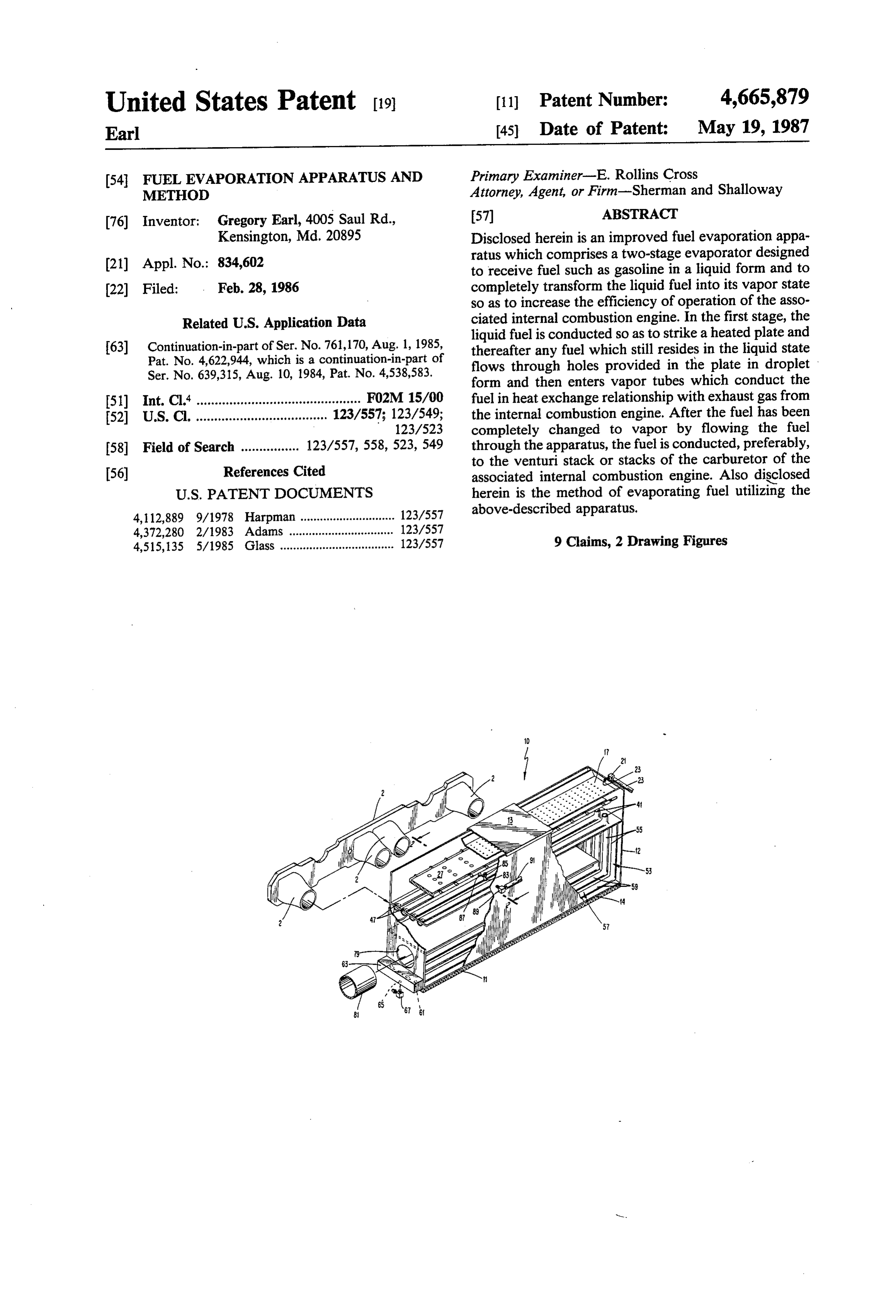
United States Patent (19) 11 Patent Number: 4,665,879 Earl 45 Date of Patent: May 19, 1987 (54 FUEL EVAPORATION APPARATUS AND Primary Examiner-E. Rollins Cross METHOD Attorney, Agent, or Firm-Sherman and Shalloway 76) Inventor; Gregory Earl, 4005 Saul Rd., 57 ABSTRACT Kensington, Md. 20895 Disclosed herein is an improved fuel evaporation appa
ratus which comprises a two-stage evaporator designed to receive fuel such as gasoline in a liquid form and to (22 Filed: Feb. 28, 1986 completely transform the liquid fuel into its vapor state so as to increase the efficiency of operation of the asso
Related U.S. Application Data ciated internal combustion engine. In the first stage, the liquid fuel is conducted so as to strike a heated plate and 63 Continuation-in-part of Ser. No. 761,170, Aug. 1, 1985, thereafter any fuel which still resides in the liquid state Pat. No. 4,622,944, which is a continuation-in-part of flows through holes provided in the plate in droplet Ser. No. 639,315, Aug. 10, 1984, Pat. No. 4,538,583. form and then enters vapor tubes which conduct the 51) Int. Cl. ............................................. FO2M 15/00 fuel in heat exchange relationship with exhaust gas from 52 U.S. Cl. .................................... 123/557; 123/549; the internal combustion engine. After the fuel has been 123/523 completely changed to vapor by flowing the fuel 58 Field of Search ................ 123/557, 558, 523, 549 through the apparatus, the fuel is conducted, preferably, to the venturi stack or stacks of the carburetor of the 56) References Cited associated internal combustion engine. Also disclosed
4,112,889 9/1978 Harpman ............................. 123/557 above-described apparatus.
4,372,280 2/1983 Adams .... ... 123/557 4,515,135 5/1985 Glass ................................... 123/557 9 Claims, 2 Drawing Figures
Page 2
Drawing sheet — no readable text.
Page 3
Drawing sheet — no readable text.
Page 4
SUMMARY OF THE INVENTION
FUEL EVAPORATION APPARATUS AND
METHOD In prior application Ser. No. 06/761,170, a fuel evap orator device is disclosed in great detail, including its
This application is a continuation-in-part of U.S. ap- 5 association into the fuel supply system and electrical plication Ser. No. 06/761,170, filed Aug. 1, 1985, now system of an internal combustion engine device. For U.S. Pat. No. 4,622,944, which is a continuation-in-part simplicity, the present invention will be disclosed herein of U.S. patent application Ser. No. 06/639,315 filed in terms of the elements of the evaporator perse and the Aug. 10, 1984, now U.S. Pat. No. 4,538,583. Each of 10 details of the electrical system and fuel supply system of these prior U.S. patent applications are hereby incorpo the associated internal combustion engine will be shown rated by reference in this application. only as necessary and essential to the understanding of the teachings of the present invention. In the detailed
BACKGROUND OF THE INVENTION description of the preferred embodiments which fol In the prior applicatiop, an improved apparatus for 15 lows hereinafter, when elements corresponding to ele evaporating fuel was disclosed which quite efficiently ments disclosed in the prior patent application are to be evaporates liquid fuel so that it is presented to the carbu included in association with the present invention, this retor of an internal combustion engine in completely willThe be stated in detail.
present invention includes the following interre vaporized form so as to increase the efficiency of the combustion of the internal combustion engine. While 20 lated elements:
(a) In a first aspect of the present invention, the inven the invention disclosed in the prior patent application operates quite efficiently, Applicant has conducted fur tive evaporator is in a rectangular cubic form having a renovable cover which reveals an inlet chamber con ther research to devise ways of more efficiently and taining a trough having a plurality of micropores economically heating the fuel to its vapor point so as to therein.
further improve upon the teachings of the invention 25 chamberLiquid with fuel from the fuel tank is supplied to this trough by the vehicle fuel pump.
disclosed in the prior application. During this research, (b) With the cover securely fastened over the chan it was discovered that a more efficient approach to the ber, liquid fuel may fill up the inlet problems of fuel evaporation might include a lesser sufficient fuel is present, the fuel is chamber forced and when through the emphasis upon the use of glow plugs to heat the plate or micropores and sprays into the first stage evaporation plates on which the liquid fuel impinges and a greater 30 chamber below. The first stage evaporation chamber emphasis upon the use of the heat found in exhaust gases created by the operation of the internal combustion has a floor which comprises an apertured plate which is engine. Thus, in order to increase efficiency while re heated by a plurality of heating devices such as glow ducing the drain on the vehicle battery and generating plugs.
the
When the fuel in its sprayed form impinges upon apertured plate, the fuel is heated and some of it system, the present invention was created. 35 evaporates to form
Applicant is aware of several prior art documents ducted through thefuel vapor. The fuel vapor is con which are believed to be only generally related to the evaporation chamber whileandun-vaporized plate into the second stage fuel flows teachings of the present invention, as follows: through the apertures in the apertured plate and enters U.S. Pat. No. 541,773 to Mead. the above-described second stage evaporation chamber. U.S. Pat. No. 1,465,574 to Bannister. (c) The second stage evaporation chamber comprises U.S. Pat. No. 1,603,660 to Cassella. a chamber bounded on its bottom with a plate having U.S. Pat. No. 1,980,496 to Musselwhite. mounted on its top and bottom a plurality of conduits, U.S. Pat. No. 1,608,018 to Eldred. preferably of semi-circular cross-section. Thus, liquid U.S. Pat. No. 1,997,497 to Pogue. 45 fuel droplets in the second stage evaporation chamber U.S. Pat. No. 2,049,687 to Chamberland, et al. flows through these vapor tubes. Meanwhile, on the U.S. Pat. No. 2,219,522 to Hinsch. underside of the plate bounding the bottom of the sec U.S. Pat. No. 2,306,897 to Ollig. ond stage, evaporation chamber, a further chamber is U.S. Pat. . 2,650,582 to Green. formed in which exhaust gases are conducted so as to U.S. Pat. No. 3,872,191 to Walcker. 50 heat the plate and the passages connected thereto as U.S. Pat. No. 3,886,919 to Freeman. well as any vapors or liquid droplets which flow U.S. Pat. . 3,916,859 to Fossum. through the tubes. Thus, liquid droplets and vaporized U.S. Pat. . 3,961,616 to Brown. fuel are conducted through the tubes which extend not U.S. Pat. No. 4,015,569 to Leshner, et al. only along the full longitudinal extent of the plate U.S. Pat. . 4,106,457 to Totten, et al. 55 bounding the bottom of the second stage evaporation U.S. Pat. . 4,112,889 to Harpman. chamber, but also extend along one vertical wall of the U. S. Pat. . 4,139,582 to Collins. - evaporation device and along the bottom wall with the U.S. Pat. . 4,151,821 to Wichman, et al. walls on which the vapor tubes extend bounding the U.S. Pat. . 4,212,274 to Quick. chamber in which exhaust gases are conducted. U.S. Pat. . 4,213,433 to Day. 60 (d) By the time the fuel has reached the end of the U.S. Pat. . 4,223,652 to Budnicki. vapor tubes, it is completely vaporized and enters a U.S. Pat. . 4,349,001 to Wagner. manifold from which it is conducted to a location such U.S. Pat. No. 4,350,134 to Sparks. as the venturi stack of a carburetor where the com Japanese Pat. No. 490,266 to Feroldi. pletely vaporized fuel is mixed with air and then con While some of these patents teach some of the aspects. 65 ducted into the cylinders of the internal combustion of the present invention, Applicant believes that none of engine.
them teach, either singly or in combination, all of the (e) The heating devices contained in the apertured inventive features combined into the present invention. plate are provided with electrical power by an electrical
Page 5
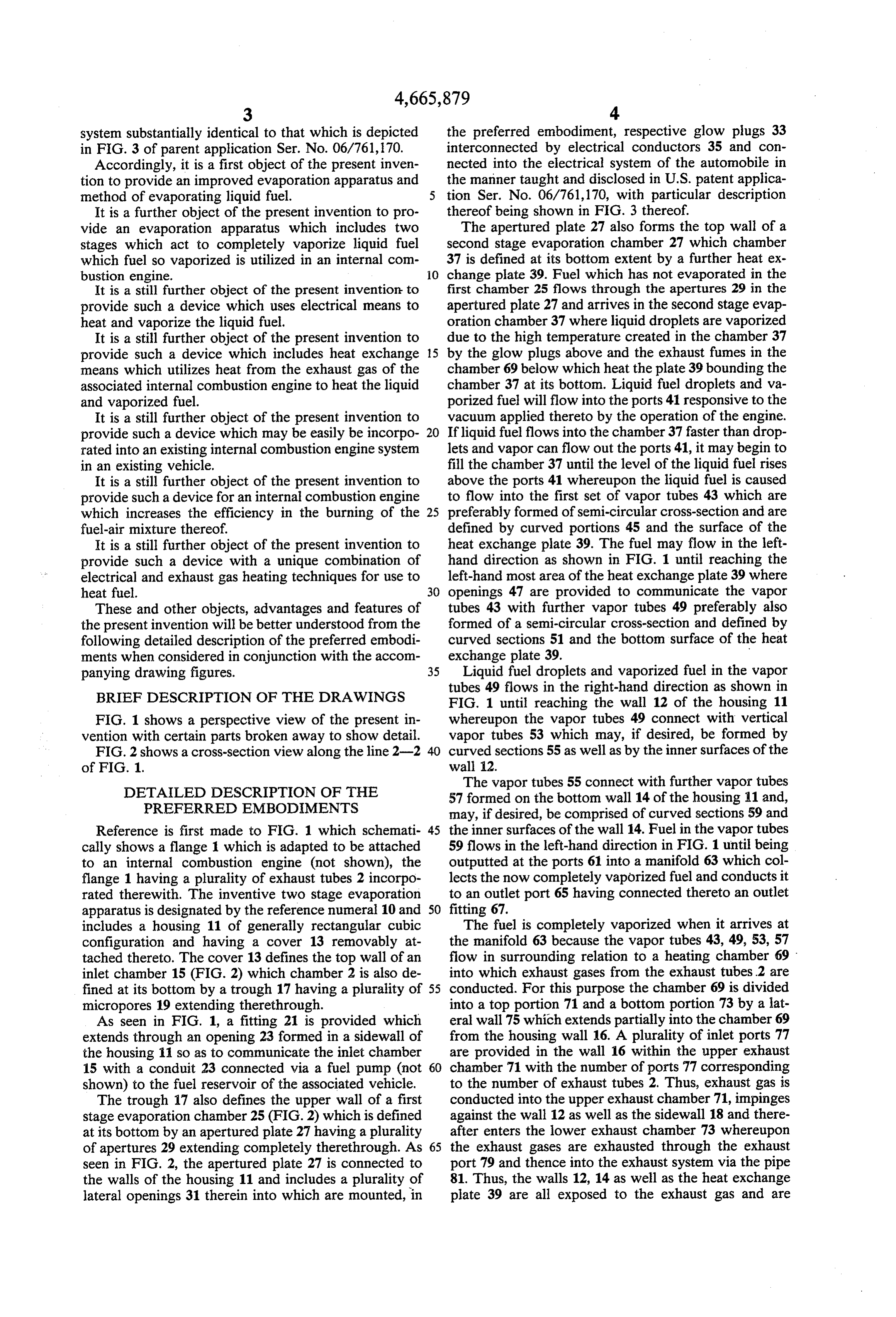
system substantially identical to that which is depicted the preferred embodiment, respective glow plugs 33 in FIG. 3 of parent application Ser. No. 06/761,170. interconnected by electrical conductors 35 and con Accordingly, it is a first object of the present inven nected into the electrical system of the automobile in tion to provide an improved evaporation apparatus and the manner taught and disclosed in U.S. patent applica method of evaporating liquid fuel. 5 tion Ser. No. 06/761,170, with particular description It is a further object of the present invention to pro thereof being shown in FIG. 3 thereof. vide an evaporation apparatus which includes two The apertured plate 27 also forms the top wall of a stages which act to completely vaporize liquid fuel second stage evaporation chamber 27 which chamber which fuel so vaporized is utilized in an internal com 37 is defined at its bottom extent by a further heat ex bustion engine. 10 change plate 39. Fuel which has not evaporated in the It is a still further object of the present invention to first chamber 25 flows through the apertures 29 in the provide such a device which uses electrical means to apertured plate 27 and arrives in the second stage evap heat and vaporize the liquid fuel. oration chamber 37 where liquid droplets are vaporized It is a still further object of the present invention to due to the high temperature created in the chamber 37 provide such a device which includes heat exchange 15 by the glow plugs above and the exhaust fumes in the means which utilizes heat from the exhaust gas of the chamber 69 below which heat the plate 39 bounding the associated internal combustion engine to heat the liquid chamber 37 at its bottom. Liquid fuel droplets and va and vaporized fuel. porized fuel will flow into the ports 41 responsive to the It is a still further object of the present invention to vacuum applied thereto by the operation of the engine. provide such a device which may be easily be incorpo 20 If liquid fuel flows into the chamber 37 faster than drop rated into an existing internal combustion engine system lets and vapor can flow out the ports 41, it may begin to in an existing vehicle. fill the chamber 37 until the level of the liquid fuel rises It is a still further object of the present invention to above the ports 41 whereupon the liquid fuel is caused provide such a device for an internal combustion engine to flow into the first set of vapor tubes 43 which are which increases the efficiency in the burning of the 25 preferably formed of semi-circular cross-section and are fuel-air mixture thereof. defined by curved portions 45 and the surface of the It is a still further object of the present invention to heat exchange plate 39. The fuel may flow in the left provide such a device with a unique combination of hand direction as shown in FIG. 1 until reaching the electrical and exhaust gas heating techniques for use to left-hand most area of the heat exchange plate 39 where heat fuel. 30 openings 47 are provided to communicate the vapor These and other objects, advantages and features of tubes 43 with further vapor tubes 49 preferably also the present invention will be better understood from the formed of a semi-circular cross-section and defined by following detailed description of the preferred embodi curved sections 51 and the bottom surface of the heat ments when considered in conjunction with the accom exchange plate 39.
panying drawing figures. 35 Liquid fuel droplets and vaporized fuel in the vapor
BRIEF DESCRIPTION OF THE DRAWINGS
tubes 49 flows in the right-hand direction as shown in
FIG. 1 until reaching the wall 12 of the housing 11
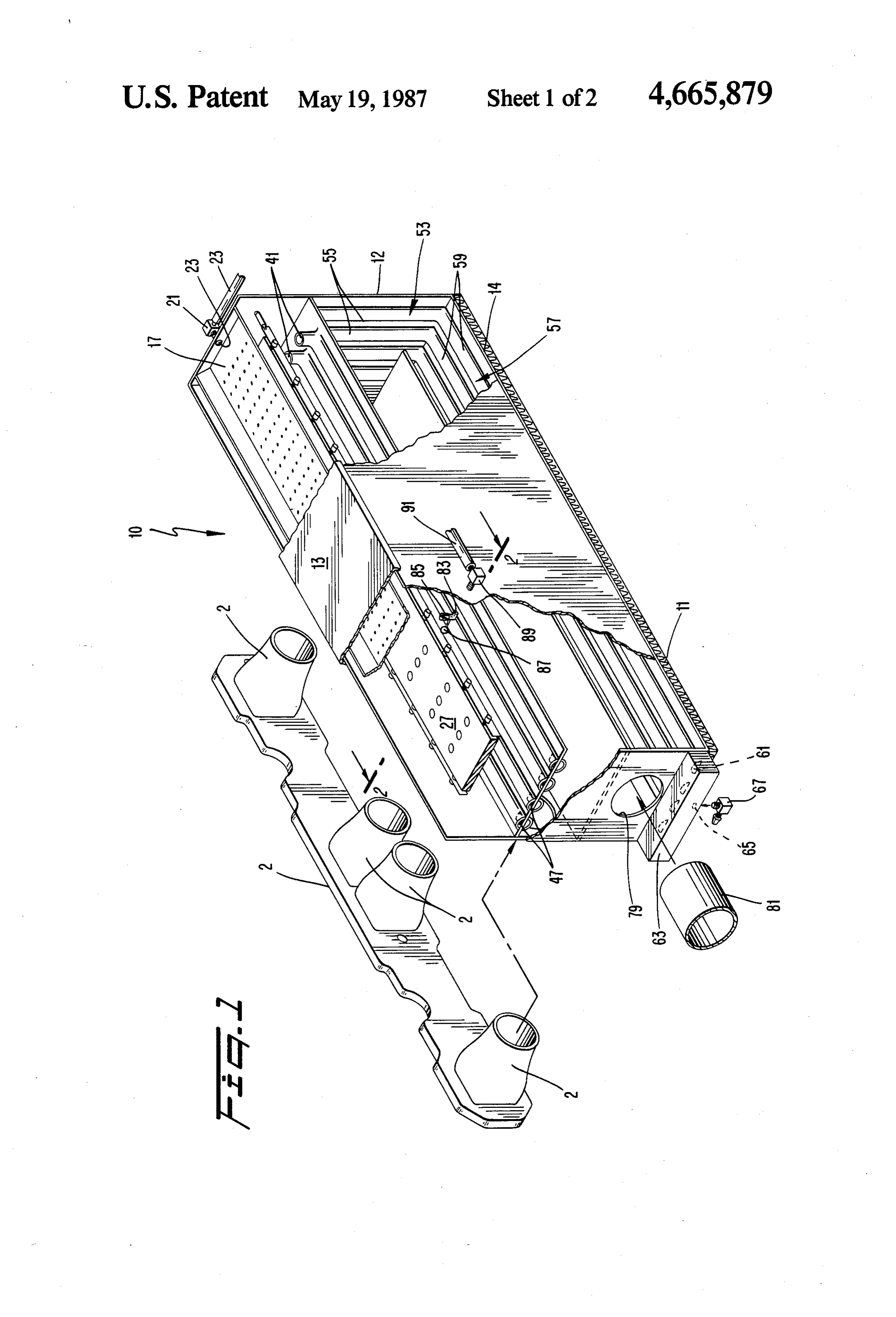
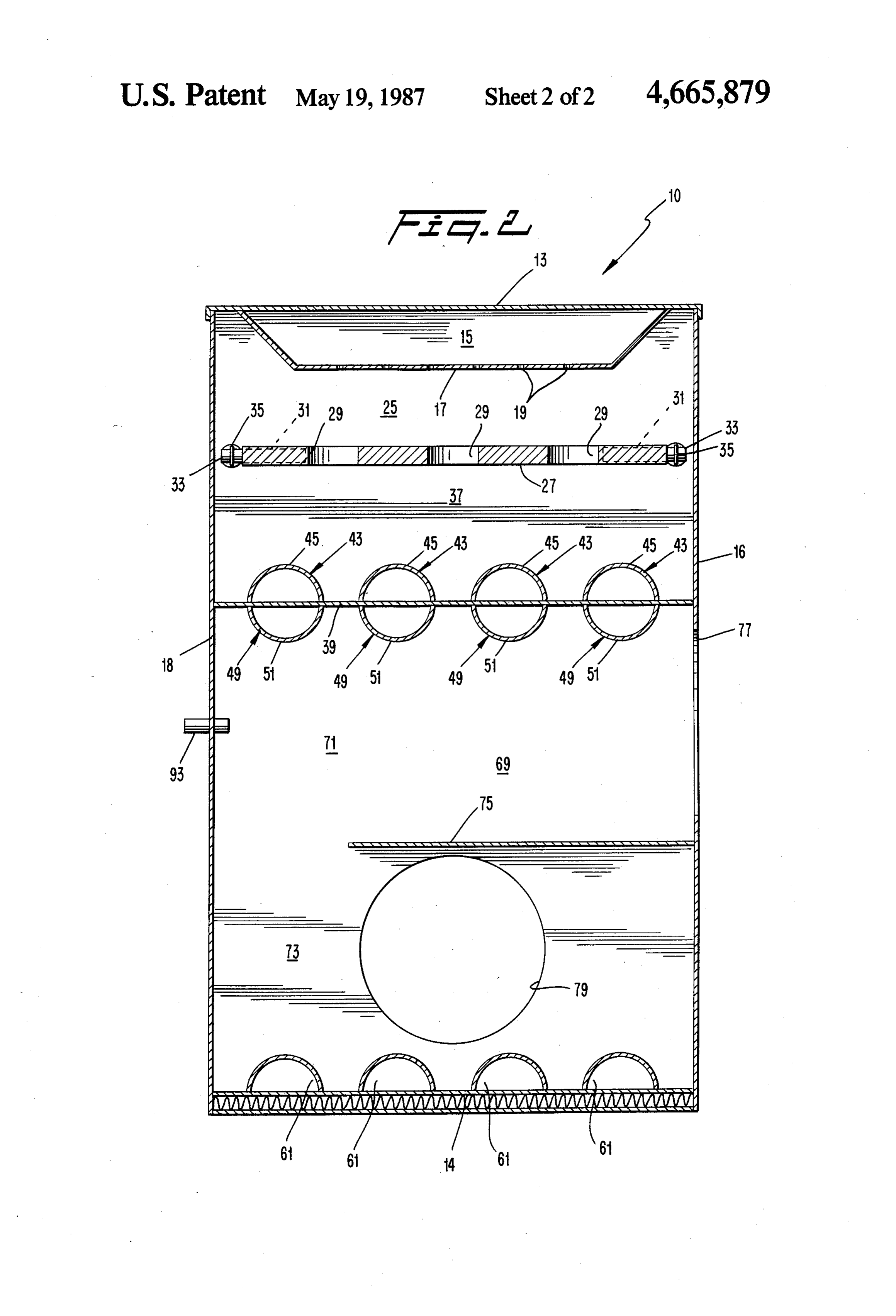
FIG. 1 shows a perspective view of the present in whereupon the vapor tubes 49 connect with vertical vention with certain parts broken away to show detail. vapor tubes 53 which may, if desired, be formed by FIG. 2 shows a cross-section view along the line 2-2 40 curved sections 55 as well as by the inner surfaces of the of FIG. 1. wall 12.
DETAILED DESCRIPTION OF THE
The vapor tubes 55 connect with further vapor tubes
PREFERRED EMBODIMENTS
57 formed on the bottom wall 14 of the housing 1 and, may, if desired, be comprised of curved sections 59 and
Reference is first made to FIG. 1 which schemati 45 the inner surfaces of the wall 14. Fuel in the vapor tubes cally shows a flange 1 which is adapted to be attached 59 flows in the left-hand direction in FIG. 1 until being to an internal combustion engine (not shown), the outputted at the ports 61 into a manifold 63 which col flange 1 having a plurality of exhaust tubes 2 incorpo lects the now completely vaporized fuel and conducts it rated therewith. The inventive two stage evaporation to an outlet port 65 having connected thereto an outlet apparatus is designated by the reference numeral 10 and 50 fitting 67.
includes a housing 11 of generally rectangular cubic The fuel is completely vaporized when it arrives at configuration and having a cover 13 removably at the manifold 63 because the vapor tubes 43, 49, 53, 57 tached thereto. The cover 13 defines the top wall of an flow in surrounding relation to a heating chamber 69 inlet chamber 15 (FIG. 2) which chamber 2 is also de into which exhaust gases from the exhaust tubes 2 are fined at its bottom by a trough 17 having a plurality of 55 conducted. For this purpose the chamber 69 is divided micropores 19 extending therethrough. into a top portion 71 and a bottom portion 73 by a lat As seen in FIG. 1, a fitting 21 is provided which eral wall 75 which extends partially into the chamber 69 extends through an opening 23 formed in a sidewall of from the housing wall 16. A plurality of inlet ports 77 the housing 11 so as to communicate the inlet chamber are provided in the wall 16 within the upper exhaust 15 with a conduit 23 connected via a fuel pump (not 60 chamber 71 with the number of ports 77 corresponding shown) to the fuel reservoir of the associated vehicle. to the number of exhaust tubes 2. Thus, exhaust gas is The trough 17 also defines the upper wall of a first conducted into the upper exhaust chamber 71, impinges stage evaporation chamber 25 (FIG. 2) which is defined against the wall 12 as well as the sidewall 18 and there at its bottom by an apertured plate 27 having a plurality after enters the lower exhaust chamber 73 whereupon of apertures 29 extending completely therethrough. As 65 the exhaust gases are exhausted through the exhaust seen in FIG. 2, the apertured plate 27 is connected to port 79 and thence into the exhaust system via the pipe the walls of the housing 11 and includes a plurality of 81. Thus, the walls 12, 14 as well as the heat exchange lateral openings 31 therein into which are mounted, in plate 39 are all exposed to the exhaust gas and are
Page 6
heated thereby. Thus, since these walls at least partially of the fuel is conducted to the vapor carburetor via the form the vapor tubes through which the liquid and apparatus 10.
vaporized fuel flow, the fuel is heated and completely Accordingly, an improved fuel evaporation appara vaporized by this heat exchange relation. tus has been disclosed hereinabove which fulfills each The outlet fitting 67 may, if desired, be connected via and every object delineated hereinabove. It is contem tubing (not shown) to the venturi stack of a carburetor plated that various modifications, alterations and associated with an internal combustion engine not form changes in the teachings of the present invention may ing a part of the present invention, however, if desired, occur to those skilled in the art. Accordingly, it is in the outlet fitting 67 may be connected via such tubing to tended that the invention should not be limited to the any fuel supply system desired such as fuel injectors, 10 embodiments specifically described hereinabove, but etc. rather that the invention disclosed herein should only With reference back to FIG. 1 it is seen that within be limited by the scope of the appended claims. the chamber 37, a port 83 is provided which is at a I claim:
slightly lower elevation than the elevation of the vapor 1. An improved evaporation apparatus for use in the tube inlet 41. A butterfly valve 85 is provided within the 15 fuel supply system of an internal combustion engine, port 83 and this butterfly valve is operated by the float comprising:
87. The valve 85 and float 87 are designed so that if (a) housing means including an opening closed by liquid fuel accumulates in the chamber 37 a predeter removable cover means;
mined level higher than the inlets 41, the float 87 will (b) inlet means for admission of fuel to inlet chamber rise to a sufficient level that the butterfly valve 85 will 20 means defined by said cover means and by trough open thereby allowing liquid fuel to be drained from the means mounted in said housing means, said trough chamber 37 out the fitting 89 and back to the reservoir means having a plurality of pores extending there (not shown) via a conduit 91. through;
As shown in FIG. 2, a temperature sensor 93 may be (c) first evaporation chamber means defined by said provided in the upper exhaust chamber 71 of the cham 25 trough means and by an apertured plate controlla ber 69. The purpose for this temperature sensor 93 is to bly heated by heating means, fuel entering said first sense the temperature of exhaust gases in the chamber evaporation chamber means through said pores; 69 and responsive to the temperature to control the (d) second evaporation chamber means defined by supply of fuel to the apparatus 10. In this regard, as said apertured plate and by a heat exchange plate, disclosed in parent application Ser. No. 06/761,170, 30 fuel entering said second evaporation chamber when the associated internal combustion engine has not means through apertures in said apertured plate, been used for long periods of time or, for example, on said heat exchange plate being heated by exhaust cold mornings, the associated carburetor may be pro fumes of said engine; and vided with cold start valves which may be supplied (e) outlet means for evacuating vaporized fuel from directly with fuel from the reservoir while bypassing 35 said apparatus.
the evaporation apparatus. Then, responsive to a timer 2. The invention of claim 1, wherein said heating or a temperature sensor, a valve may be controlled to means includes glow plugs.
cut off the supply of fuel to the cold start valves after 3. The invention of claim 1, wherein said heat ex the engine has sufficiently warmed up. In this vein, the change temperature sensor 93 is electrically connected to a 40 tubes forplate has mounted thereon a plurality of vapor conducting fuel therethrough in heat exchange bypass valve (not shown) which may control the flow relation with said heat exchange plate. of fuel from the fuel reservoir either from the reservoir 4. The invention of directly to the carburetor or from the reservoir to the exchange plate has a first surface claim 3, further wherein said heat carburetor via the apparatus 10. As designed, as long as evaporation within said second chamber means the temperature in the chamber 69 is below a predeter cated within a heating chamber adjacent 45 and a second surface lo mined level, the above-described valve will be in a evaporation chamber means, said exhaust fumes said second position so that fuel flows directly from the fuel reser conducted through said heating chamber. being voir to the carburetor. When the temperature in the 5. The invention of claim 4, wherein at least one of chamber 69 rises above the predetermined level, as sensed by the temperature sensor 93, the above 50 second said vapor tubes is mounted on each of said first and described valve will be actuated to a position wherein surfaces.
the fuel flows from the fuel reservoir to the carburetor 6. The invention of claim 5, wherein each said vapor via the apparatus 10. If desired, a similar temperature tube comprises a curved tube section and a portion of sensor may be provided either along with the tempera one of said surfaces.
ture sensor 93 or as an alternative thereto in the aper 55 tube 7. The invention of claim 5, wherein a further vapor tured plate 27 to sense the temperature of the apertured connects with said at least one second surface plate 27 as heated by the glow plugs 33 and responsive vapor tube, said further vapor tube being mounted on a thereto to control the above-described valve. wall of said heating chamber.
As an alternative, the associated internal combustion 8. The invention of claim 1, wherein said outlet means engine may be provided with two carburetors, an idle 60 includes a manifold for collecting fuel vapors from said carburetor and a vapor carburetor. When the tempera apparatus.
ture in the exhaust gas chamber 69 is below a predeter 9. The invention of claim 4, further including a con mined level, the above-described valve may be operated duit mounted on said first surface and having a float so that the fuel solely goes through the idle carburetor. operated valve therein, said valve opening when liquid When the temperature rises above a predetermined 65 fuel in said second evaporation chamber means rises level, the above-described valve may be operated so above a predetermined xk level.
that fuel supply to the idle carburetor is shut off and all
Provenance
- Collection
- Cited prior art
- Original PDF
- patentimages.storage.googleapis.com →
- Filed
- 1986-02-28
- Pages
- 6
- Method
- pdftotext (the PDF's own text layer) + pdftoppm 300dpi page scans
- Source
- Google Patents bibliographic record
- Granted
- 1987-05-19
- Inventors
- Gregory Earl
- Transcribed from
- patentimages.storage.googleapis.com →