patent · US4643212
Hot liquid thermal energy storage tank and method
17 February 1987
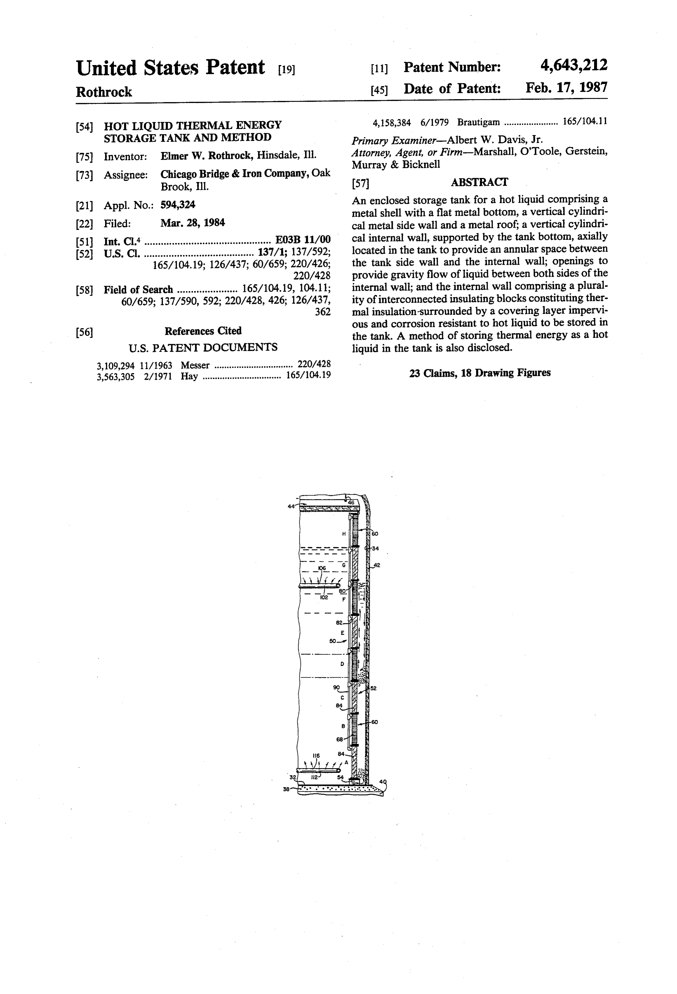
Page 1 — bibliographic record
United States Patent (19) 11 Patent Number: 4,643,212 Rothrock 45 Date of Patent: Feb. 17, 1987 54 HOT LIQUID THERMAL ENERGY 4,158,384 6/1979 Brautigan ...................... 65/104.11 STORAGE TANK AND METHOD Primary Examiner-Albert W. Davis, Jr. (75) Inventor: Elmer W. Rothrock, Hinsdale, Ill. Attorney, Agent, or Firm-Marshall, O'Toole, Gerstein, Murray & Bicknell 73) Assignee: Chicago Bridge & Iron Company, Oak 57 ABSTRACT Brook, Ill.
(21) Appl. No.: 594,324 An enclosed storage tank for a hot liquid comprising a metal shell with a flat metal bottom, a vertical cylindri 22 Filed: Mar. 28, 1984 cal metal side wall and a metal roof; a vertical cylindri 51) Int. Cl'.............................................. E03B 11/00 cal internal wall, supported by the tank bottom, axially 52 U.S. Cl. ........................................ 137/1; 137/592; located in the tank to provide an annular space between 165/104.19; 126/437; 60/659; 220/426; the tank side wall and the internal wall; openings to 220/428 provide gravity flow of liquid between both sides of the 58 Field of Search ...................... 165/104.19, 104.11; internal wall; and the internal wall comprising a plural 60/659; 137/590,592; 220/428,426; 126/437, ity of interconnected insulating blocks constituting ther 362 mal insulation-surrounded by a covering layer impervi (56) References Cited ous and corrosion resistant to hot liquid to be stored in the tank. A method of storing thermal energy as a hot
3,109,294 11/1963 Messer ................................ 220/428 3,563,305 2/1971 Hay ................................ 165/104.19 23 Claims, 18 Drawing Figures
Page 2
Drawing sheet — no readable text.
Page 3
Drawing sheet — no readable text.
Page 4
Drawing sheet — no readable text.
Page 5
Drawing sheet — no readable text.
Page 6
Drawing sheet — no readable text.
Page 7
liquid to contact and heat the metal tank shell. Further
HOT LIQUID THERMAL ENERGY STORAGE more, many insulation materials are readily corroded, TANK AND METHOD and thus are not useable, when placed in direct contact with a molten salt.
This invention relates to storage of liquids. More 5 From the above discussion it is clear that a need exists particularly, this invention is concerned with a liquid for an improved storage tank for storing thermal energy storage tank for storing thermal energy in the form of a in the form of a high temperature liquid, particularly a high temperature liquid, such as a molten salt. molten salt.
SUMMARY OF THE INVENTION
Liquids have been stored for many years in metal According to the invention, an enclosed liquid stor tanks and vessels at ambient temperature. In recent age tank, desirably for storing thermal energy as a hot years there has been substantial interest in storing ther liquid, is provided comprising a metal shell with a flat mal energy in the form of a hot liquid, such as hot wa metal bottom, a vertical cylindrical metal side wall and ter, oil or a molten salt, for subsequent use as needed or 15 a metal roof a vertical cylindrical internal wall, sup appropriate. The energy so stored can be obtained from ported by the tank bottom, axially located in the tank to a power generating plant for subsequent electric gener provide an annular space between the tank side wall and ation or it can be obtained from a solar energy collector the internal wall; means to provide gravity flow of and used later for heating purposes or electric power liquid between both sides of the internal wall; and with generation. 20 the internal wall comprising a plurality of intercon A thermal energy storage tank will generally always nected insulating blocks constituting thermal insulation be full of liquid. The liquid, however, will be removed surrounded by a covering layer impervious and corro hot from the tank when energy is needed and after the sion resistant to liquid to be stored in the tank. heat is removed the cold liquid will be returned to the According to a second aspect of the invention, a tank for storage. The liquid in the tank will accordingly 25 method is provided comprising feeding a hot liquid into be at two different temperatures a substantial amount of an enclosed liquid storage tank having a metal shell the time with a cold layer stratified beneath an upper with a flat metal bottom, a vertical cylindrical internal hot layer. When thermal energy is available to heat the wall, supported by the tank bottom, axially located in liquid, the cold liquid is removed from the lower part of the tank to provide an annular space between the tank the stored volume, heated and then returned to the 30 side wall and the internal wall; ports or openings in the upper part of the tank. In this way the entire stored internal wall along the flat metal bottom to provide volume can be heated. Thus, the volume ratios of the gravity flow of liquid between both sides of the internal cold liquid layer to the total volume can vary between wall; and the internal wall comprising a plurality of 0 and 1. interconnected insulating blocks constituting thermal Although spherical tanks can be used they are costly. 35 insulation surrounded by a covering layer impervious A clear cost advantage is inherent in a flat bottom cylin and corrosion resistant to liquid to be stored in the tank, drical tank, principally because the load can be trans with said feeding continuing until the tank contains a ferred directly to the supporting earth. layer of hot liquid within the internal wall and at least a Unless the storage tank is suitably insulated, substan layer of cold liquid in the annular space and along the tial heat would be lost by convection, conduction and 40 flat metal bottom at least for the depth of the ports; radiation from the hot liquid to the surrounding air. The removing hot liquid from the tank in a volume equal to insulation is desirably placed on the outside of the tank cold liquid fed to the tank so that the total liquid volume because functionally suitable insulation for use on the in the tank is about constant and substantially fills the inside tank wall may not be available or, if available, the tank; and removing cold liquid from the tank in a vol cost would be too great. The result of external insula 45 ume equal to hot liquid fed to the tank until the layer of tion is that the hot liquid directly contacts the tank side cold liquid at the bottom of the tank has a depth ade wall. While such direct liquid contact is acceptable with quate for the thermocline to be above the ports so that moderately heated liquids, it is undesirable to have high thereby the hot liquid cannot flow from within the temperature liquids, such as molten salts above 400 C., space surrounded by the internal wall, through the in contact with the tank metal shell. At a moderately 50 ports and into the annular space. The tank would be high temperature, the weakening effect on the wall initially charged with "cold liquid' to fill the annular strength is countered by increasing the design thickness space, then the heating cycle could begin. of the shell but for higher temperatures (> 700 C.) the The covering layer used on the blocks protects the weakening effect can create a hazardous condition. insulation against the corrosive action of the hot liquid, Also, severe temperature stresses are produced in the 55 such as a molten salt. Furthermore, since the inner wall metal side wall or shell as a result of the thermocline functions as a thermal barrier, liquid in the annular where the hot and cold layers merge, and from the space is at a substantially lower temperature than the temperature difference between the cylindrical shell main body of liquid in the tank, even when such liquid and bottom. is heated to a maximum predetermined temperature. To minimize capital costs, it is desirable to fabricate a 60 This permits the tank wall to be fabricated of a less storage tank from the least expensive metal. However, expensive metal than would otherwise be required and molten salts at high temperatures, i.e. above 550 C., are eliminates the hazard which would result from the very corrosive to carbon steel and even stainless steels. weakening effect of the exceptionally high (> 700° C.) While a layer of expensive refractory insulation on the temperatures. The tank bottom can also be fabricated of inside of the tank might be considered away to keep the 65 less expensive metal since a layer of relatively cold metal shell at a lower temperature and out of contact liquid is maintained at the bottom at all times. This with it, such an arrangement places the tank in jeopardy relatively cold layer has a depth great enough to keep if a hole or fracture in the insulation permits the hot the thermocline between the hot liquid layer and the
Page 8
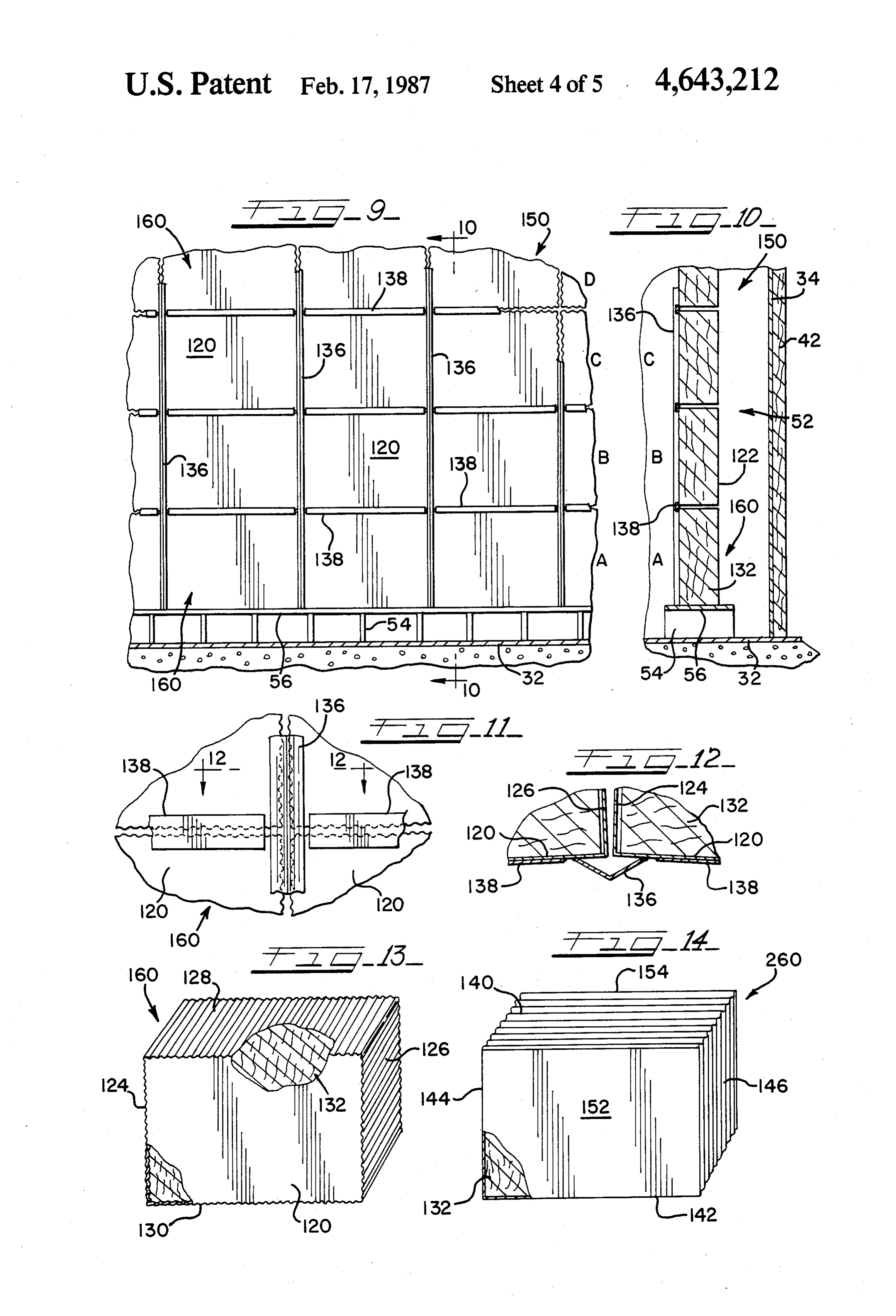
cold liquid layer higher than or above the ports or open FIG. 13 is an isometric view of the insulating block ings at the bottom of the internal wall which permit used in forming the tank internal wall shown in FIGS. liquid flow between the annular space and the space 9 to 12;
surrounded by the internal wall. As a result, hot liquid FIG. 14 is an isometric view of an insulating block cannot flow into the annular space. 5 with the sides corrugated parallel to the front and back, The means to provide gravity flow of liquid between rather than lateral to the front and back as shown in both sides of the internal wall can constitute openings at FIG. 13;
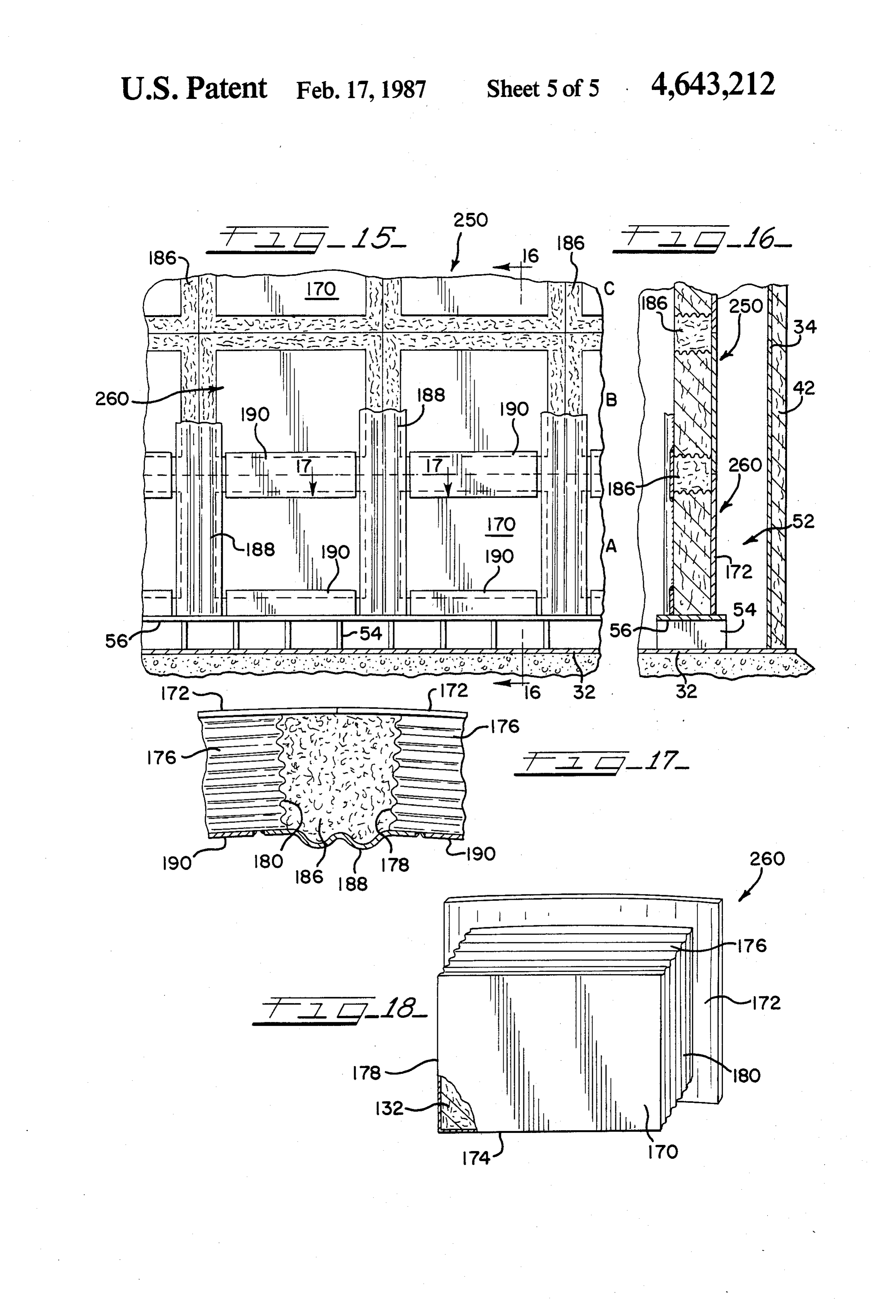
FIG. 15 is an elevational view of a third embodiment the bottom of the internal wall.
Each of the blocks can be substantially of the same 10 ofFIG. internal wall provided by the invention; shape and size. Thus, the blocks can have rectangular of FIG. 1615;is a sectional view taken along the ine 16-16 vertical front and rear covering layers. The blocks can FIG. 17 is a sectional view taken along the line also have curved front and rear layers. Regardless of 17-17 of FIG. 15; and their shape and size the blocks will usually be of about FIG. 18 is an isometric view of the insulating block uniform thickness.
The covering layer of the blocks is desirably a metal used in forming the tank internal wall shown in FIGS.
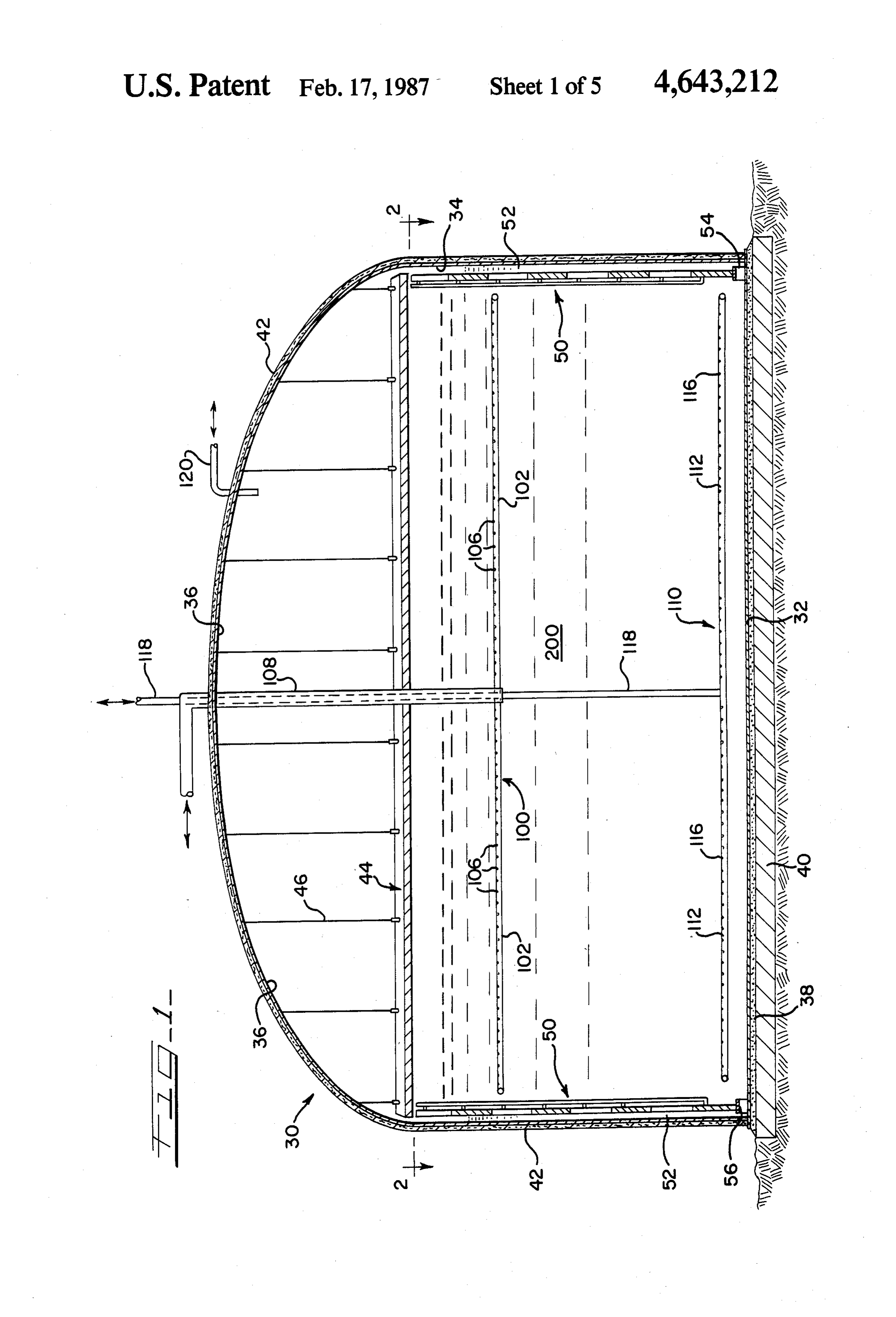
which is stable at high temperatures and which is not corroded by the molten salt. DETAILED DESCRIPTION OF THE The inner wall can be fabricated of a plurality of rings DRAWINGS or courses set one on top of a lower course and with 2 To the extent it is reasonable and practical, the same each ring comprising a plurality of blocks in end-to-end or similar elements which appear in the various views of arrangement. the drawings will be identified by the same numbers. To further limit heat leak, the external surface of the The enclosed hot liquid storage tank 30 shown in tank side wall and roof can be thermally insulated. In FIG. 1 has a flat metal circular bottom 32, a vertical addition, the tank bottom can be supported on a ther- 25 circular cylindrical metal wall 34 joined at its lower mally insulated foundation although moderate heat edge to bottom 32, and a domed metal roof 36 sup transfer is desirable to keep the tank bottom from be ported by wall 34. Bottom 32 rests on a layer of granu coming too hot from the stored liquid. lar material 38, such as sand, on top of insulating con A vent conduit can communicate with the interior of crete foundation 40. Insulation 42 covers the exterior each block and extend to above the maximum liquid 30 surfaces of wall 34 and roof 36. An insulated ceiling 44 level storage capacity of the tank to prevent the blocks is suspended by rods 46 from roof 36 at a location above from ballooning due to internal gas expansion when the liquid capacity of the tank.
heated. A single vent conduit can be arranged to com Insulating freestanding internal wall 50 is located municate with a plurality of blocks. Furthermore, each inside of tank 30. Internal wall 50 is vertically and axi block in communication with the conduit can be in a 35 ally arranged in the tank so as to be spaced inwardly a separate ring. uniform distance from outer wall 34 thereby providing The covering layer of the blocks can include flat top annular space 52 between the two walls. The internal and bottom plates. Also, the blocks in each ring can be wall 50 accordingly has an essentially vertical circular staggered with respect to blocks in adjacent rings or cylindrical shape.
. . they can be assembled in a columnar arrangement. Internal wall 50 has a plurality of vertical spaced 40 apart gusset plates 54 at the lower end on which ring
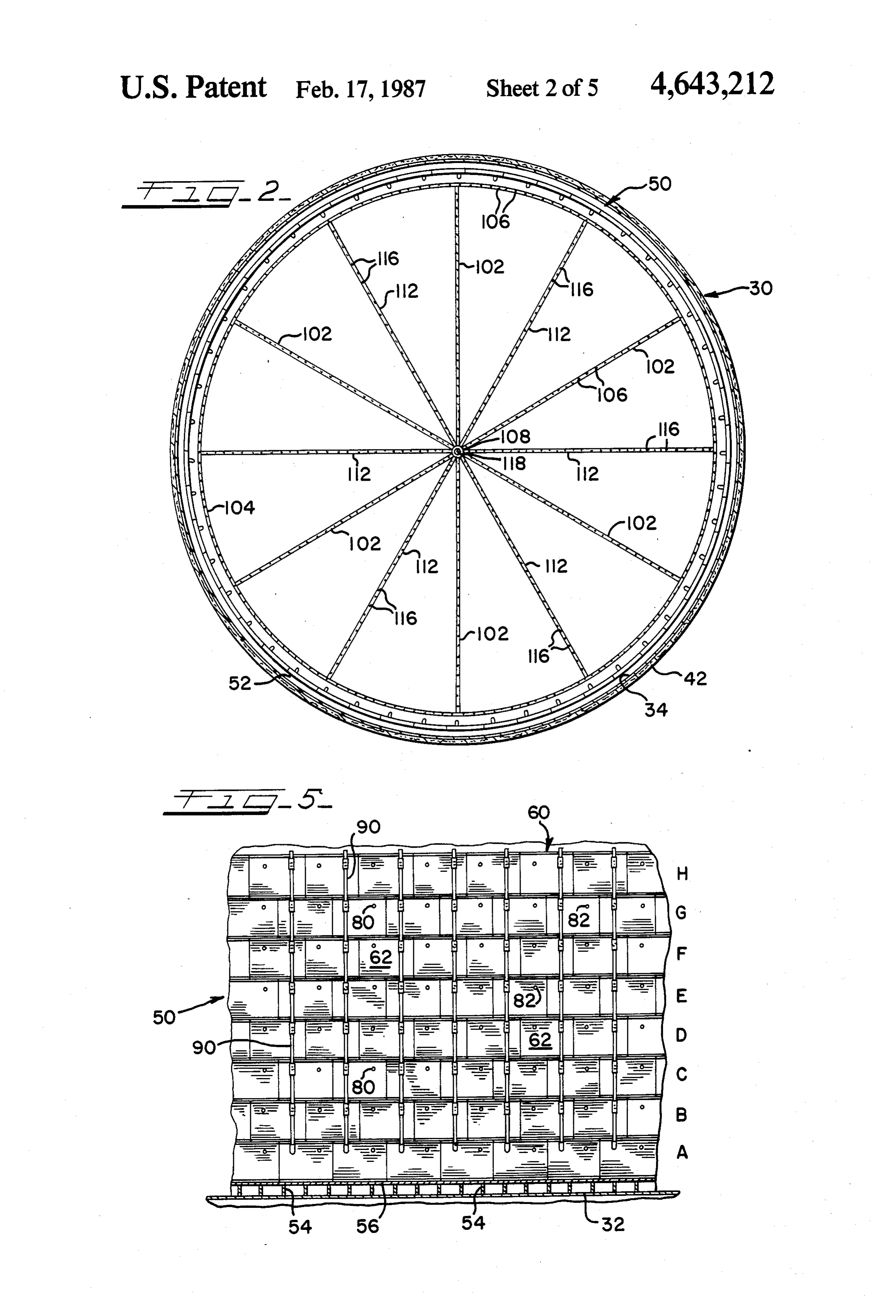
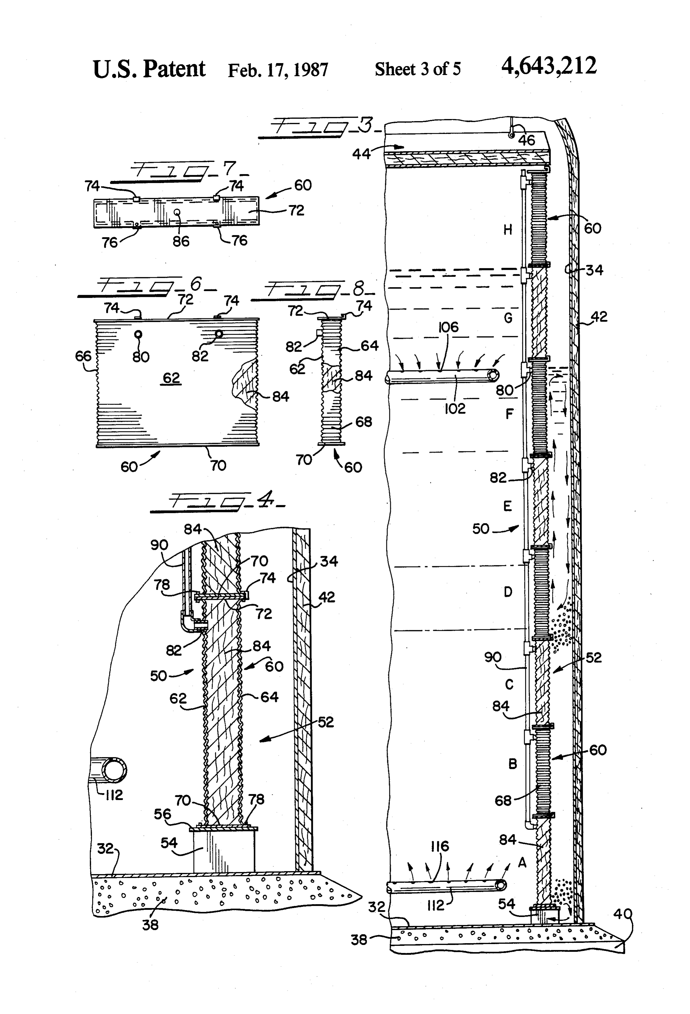
BRIEF DESCRIPTION OF THE DRAWINGS plate 56 is supported. The open space between adjacent FIG. 1 is a vertical sectional view through a liquid spaced apart gusset plates 54 permits liquid in the tank to flow into and out of annular space 52 from the central storage tank according to the invention; tank volume surrounded by internal wall 50, thus allow FIG. 2 is a sectional view taken along the line 2-2 of ing the two spaces to remain in hydrostatic equilibrium.
FIG. 3 is an enlarged vertical sectional view of a side coursesinternal
The set one wall 50 comprises a series of rings or on top of a lower ring. Thus, as shown of the tank shown in FIG. i; in FIGS. 3 and 5, the wall 50 includes eight rings A, B, FIG. 4 is an enlarged vertical sectional view of the 50 C, D, E, F, G and H. While the rings are shown of equal lower portion of the tank side shown in FIG. 3; height, they can be of different heights. FIG. 5 is an elevational view of a portion of the inter Each of the rings or courses A to G is formed of a nal wall in the tank shown in FIGS. 1 to 4; plurality of interconnected insulating blocks 60 ar FIG. 6 is a front elevational view, partially broken ranged in end-to-end abutting arrangement. While the away, of an insulating block used in forming the tank 55 blocks in adjacent rings are shown in staggered or off internal wall shown in FIGS. 1 to 5; set arrangement, they can be positioned in direct align FIG. 7 is a plan view of the insulating block shown in ment with their edges in vertical linear position, thereby FIG. 6; placing the blocks in a columnar arrangement with each FIG. 8 is a side elevational view, partially broken column adjoining two other columns.
away, of the insulating block shown in FIGS. 6 and 7; 60 Each insulating block 60 includes a metal covering FIG. 9 is an elevational view of a second embodiment layer which is impervious and corrosion resistant to of internal wall provided by the invention; liquid to be stored in the tank. The block 60 has a metal FIG. 10 is a sectional view taken along the line front wall 62, a metal rear wall 64, and metal end walls 10-10 of FIG. 9; 66 and 68 (FIGS. 6 to 8). The described walls are joined FIG. 11 is a partial elevational view of the internal 65 to flat metal bottom plate 70 and flat metal top plate 72. wall shown in FIGS. 9 and 10; Two or more clip angles 74 are welded to the rear of FIG. 12 is a sectional view taken along the line top plate 72 in such a way as to receive the rear edge of 12-12 of FIG. 11; the bottom plates 70 of blocks in the next higher ring or
Page 9
course. Two or more holes 76 are positioned along the conduit 118 runs through conduit 108 to the tank exte front edge of top and bottom plates 70 and 72 so that Ot.
bolts 78 can be used to connect stacked blocks together, Conduit 120 (FIG. 1) penetrates tank roof 36 and whether the blocks are staggered or in columnar ar provides a means for equalizing pressure in the tank rangement, and to connect the blocks to ring plate 56. with the external pressure. When desirable, internal Seams between adjoining blocks 60 need not be flow of gas by means of conduit 120 is also feasible. tightly sealed. Liquid flowing through small leaks will The storage tank described in conjunction with mix with liquid in the annular space 52 and be of no FIGS. 1 to 8 is primarily useful for storing thermal consequence. energy in the form of a hot liquid, particularly a molten The front wall 62 of each block 60 contains two stub 10 salt at a maximum temperature of about 800 to 1050 C. pipes 80 and 82 which are in fluid communication with For storing such a high temperature liquid, which often the interior of the block. Each block 60 is completely is corrosive, it is contemplated that the metal shells of filled with insulation 84, which can be supplied through blocks 60 and the spargers 100 and 110 can be made of orifice 86 in top plate 72. After the insulation is cured or Ni-Cr-Fe Alloy 600. The tank bottom 32, side wall 34 solidified, orifice 86 can be plugged. 15 and roof 36 can be made of a stainless steel, such as Desirably, a foamed refractory with a low thermal Type 304.
conductivity is used for insulation 84. The inner wall is During initial filling, there must be sufficient cold anchored to avoid floatation since the density of the liquid in the tank to fill the annular space and keep the blocks 60 would be less than some thermal energy stor bottom covered. At the start the liquid should not be age liquids, such as a molten salt. A dense refractory is 20 above 550 C. to protect the tank bottom against an preferably avoided because it would have a thermal excessively high temperature during initial filling. As conductivity exceeding that of the molten salt, making liquid is fed to the tank it also flows between gussets 54 it a poor insulator. Regardless of the type of insulation into annular space 52. Since the cold liquid protects the used, it must have adequate compressive strength to bottom and the annular space, the temperature of the resist the hydrostatic pressure to which the blocks 60 25 liquid feed stream can then be raised, such as to 1050 C. are subjected in the tank. This is because the shells of Hot liquid, such as hot molten salt, can then be fed to the blocks are made of thin flexible metal sheets which the tank 30 by sparger 100 until the hot liquid level in transfer hydrostatic loads to the insulation. the tank reaches the maximum design storage capacity The insulating blocks 60 are arranged in rings, or of the tank.
courses, as shown in the drawings, starting with the first 30 When the hot liquid is to be used, it can be withdrawn or lowermost ring A which is joined to ring plate 56 and by sparger 100. After the desired amount of thermal continuing upwardly. Obviously, assembly of one or energy has been extracted from the withdrawn hot more successive rings can be started before a lower ring liquid, the cooled liquid can be returned to the tank is fully assembled. When the rings are assembled so that through sparger 110. This cycle can be continued until the blocks in adjacent rings are staggered with respect 35 part or all of the hot liquid has been removed from the to each other, the stub pipes 80 and 82 in each block will tank. At such time as a means to heat the cold liquid in also be staggered. As a result, the stub pipes become the tank becomes available, the cold liquid can be with arranged in a series of vertical lines with stub pipes 80 drawn through sparger 110, then heated, and the hot and 82 in alternating arrangement. The stub pipes in liquid returned to the upper part of the tank through such lines are interconnected by a conduit 90 which sparger 100. This cycle can continue until part or all of extends above the top of internal wall 50. Conduit 90 is the liquid in the tank is heated except for the liquid open at the top end but is otherwise closed off against below sparger 110.
liquid stored in the tank. The purpose of conduits 90 is The liquid in annular space 52 will be at a lower to permit any gases in blocks 60 to be vented out so that temperature than the main body of liquid in hot well 200 the blocks do notballoon when a hot liquid is stored in 45 (FIG. 1). Thus, when the tank is fully charged with a the tank. Obviously, if the blocks 60 are put in a vertical hot molten salt at 950 C., the molten salt in the annular columnar arrangement, there would be no need for each space will be at a maximum of about 550°C. The ther block 60 to have two stub pipes 80 and 82 since one will mal resistance of the thermal barrier internal wall 50 suffice. results in a lower temperature in the annular space 52 A horizontal tubular sparger 100 (FIGS. 1 and 2), 50 which is acceptable for the container wall but which is having equally spaced apart radial arms 102 which com high enough to maintain the salt in a molten state. The municate with ring tube 104, is mounted in the upper tank wall 34, being at a lower temperature, can accord internal space of tank 30. Holes 106 are located in arms ingly be made of stainless steel, which is less costly than 102 and ring 104 so that liquid can be fed into, and be the alloy needed for blocks 60. Furthermore, the bot withdrawn from, the upper liquid storage space by 55 tom 32 also will be at a substantially lower temperature means of sparger 100 and conduit 108. The sparger because about two feet or so of relatively cold liquid, system permits liquid entry and removal with reduced such as at 550° C., is maintained in the tank at all times. turbulence, so as not to disturb the thermocline. The This permits the bottom to be made of stainless steel lower end of vertical conduit 108 communicates with rather than an expensive alloy. Furthermore, the sup arms 102 and the upper end extends through roof 36. 60 porting media below the tank should have a sufficiently Similarly, a horizontal tubular sparger 110 having arms high thermal conductivity so that a suitable temperature 112 joined to a ring (not shown but like the ring 104), is gradient can be maintained below sparger 110. The mounted in the lower internal space of the tank 10. described surface of arrangement thus subjects only the inner the internal wall and the internal distribution
Holes 116 are located in arms 112 and the ring so that liquid can be fed into, and be withdrawn from, the 65 piping to direct contact with the highest temperature lower liquid storage space by means of a sparger 110 molten salt.
and conduit 118. The lower end of vertical conduit 118 Because the volume of molten salts increases with communicates with arms 112 and the upper part of temperature, when the tank is fully charged with a hot
Page 10
molten salt at 950 C., it could have a depth of thirty-six abutting contact with the vertical edges of adjacent feet, although the depth of liquid in the annular space blocks. Those abutting edges are then welded together 52, being cooler, would be about thirty feet (FIG. 3). by a continuous weld. As shown in FIG. 15, the blocks Similarly, when thermally discharged, the molten salt at 260 are arranged in each succeeding higher ring so as to about 550°C. would be about thirty-one feet deep while be centered directly above a block in the lower ring the partially solidified molten salt in the annular space at with the result being that the blocks are in columnar about 300' to 330° C. would be about twenty-nine feet arrangement as well as in rings. The lower-most course deep. of blocks 260 has the lower edge of back wall 172 sup It is not considered feasible to simply apply insulation ported on and welded to the top of ring plate 56. Addi directly to the inside of tank wall 34, in place of the use O tionally, all of the horizontal girth seam joints between of internal wall 50, because the wall 34 could be threat courses or rings are welded together. Those joints are ened if a crack or opening in the insulation allowed the formed by abutting contact between the top edge of high temperature storage liquid to come into direct back wall 172 of a block 260 in a lower course and the contact with that wall. By use of an internal wall 50 lower edge of a back wall 172 of a block in a next higher small leaks of hot liquid are diffused into the lower 15 COS.
temperature molten salt in the annular space. An internal wall produced as described will be leak A second embodiment of the invention is illustrated tight. However, to complete the thermal barrier, the by FIGS. 9 to 13. The insulating block 160 (FIG. 13) vertical and horizontal channels between front walls used in this embodiment has a flat or curved vertical 170 in the courses and columns of blocks is filled with a metal front wall 120 and a flat or curved vertical metal 20 suitable deformable refractory insulating material 186. rear wall 122 (FIG. 10). The two vertical metal end After insulating material 186 is put in place, vertical walls 124, 126, the metal top 128 and the metal bottom corrugated metal strips 188 are positioned over the 130 are all corrugated lateral to the front and rear walls.
The block 160 is filled with a refractory insulating mate insulation and welded to the adjoining blocks 260. Simi larly, flat metal strips 190 are positioned over the hori rial 132 and then is evacuated to a low pressure. This Zontal rows of insulation 186 and welded to the blocks.
makes it unnecessary to vent the blocks when they Desirably, a small gap is provided between the vertical become hot in use.
FIGS. 9 to 12 illustrate an internal wall 150 formed strips 188 and the ends of the horizontal strips 190 to permit expansion.
by a series of courses or rings of blocks 160 set one on The foregoing detailed description has been given for top of a lower ring. While FIGS. 9 to 10 only show 30 clearness rings A to D, it should be understood that as many rings limitationsofshould understanding only, and no unnecessary be understood therefrom, as modifi will be used as are needed for the intended purpose. cations will be obvious to those skilled in the art. Since each ring has the same number of blocks, and What is claimed is:
because the blocks are of identical size and shape, the blocks in the sequence of progressively higher rings can 35 at 1.a temperature
An enclosed liquid storage tank for storing a liquid above 400 C. comprising:
be arranged columnar as shown in FIG. 9. The vertical a metal shell with a flat metal bottom, a vertical cylin joints between adjacent blocks are covered by an angle drical metal side wall and a metal roof; strip 136 and the strip edges are welded to the respec a vertical circular cylindrical essentially freestanding tive blocks. Similarly, flat horizontal strips 138 are posi internal wall, supported by the tank bottom, axially tioned to span the horizontal joints between blocks and 40 located in the tank to provide an annular space then are welded to the blocks. The ends of horizontal strips 138 terminate a short distance from the vertical between the tank side wall and the internal wall; strips 136 so that expansion and contraction can be means to provide gravity flow of liquid between both accommodated. While this provides small gaps in the sides of the internal wall; and wall, the small amount of liquid leaking through is in 45 thenected internal wall comprising a plurality of intercon insulating blocks constituting thermal insu consequential.
FIG. 14 illustrates an insulating block 260 which is lation surrounded by a covering layer impervious quite similar to block 160. However, block 260 has and corrosion resistant to liquid to be stored in the metal top and bottom walls 140, 142 and metal end walls tank.
144, 146 with the corrugations running parallel to the 50 2. An enclosed liquid storage tank according to claim flat or curved front and rear walls 152 and 154. Block 1 in which the means to provide gravity flow of liquid 260 also contains refractory insulation 132. between both sides of the internal wall includes open A third embodiment of internal wall 250 is illustrated ings at the bottom of the internal wall. by FIGS. 15 to 18. The internal wall 250 is formed of 3. An enclosed liquid storage tank according to claim insulating blocks 260 shown in FIG. 18 to have a rectan 55 1 in which the covering layer is metal. gular flat metal front wall 170, a single-curved metal rear 4. An enclosed liquid storage tank according to claim wall 172 curved to the radius of the inner wall 250, 1 in which the blocks are largely of the same shape and corrugated metal horizontal top and bottom walls 174, SZC.
176 and corrugated metal vertical end or side walls 178, 5. An enclosed liquid storage tank according to claim 180. The corrugations in the top, bottom and end walls 60 1 in which the blocks have vertical front and rear cover are all parallel to the front wall 170. A cast refractory ing layers and the blocks are of about uniform thickness. insulation material 132 fills the space inside each block 6. An enclosed liquid storage tank according to claim 260. 1 in which the inner wall comprises a plurality of rings As is clearly shown in FIG. 18, the single-curved rear or courses set one on top of a lower ring and each ring wall 172 is substantially larger in length and height than 65 comprises a plurality of blocks in end to end arrange front wall 170. Accordingly, in forming inner wall 250, ment.
the blocks 260 are arranged in rings or courses A, B, C, 7. An enclosed liquid storage tank according to claim etc. with the vertical edges of each block wall 172 in 1 in which the external surface of the tank side wall and
Page 11
roof are thermally insulated and the tank bottom is quate for the thermocline to be above the ports so supported on a thermally insulated foundation. that thereby the hot liquid cannot flow from within 8. An enclosed liquid storage tank according to claim the space surrounded by the internal wall, through 1 including a thermally insulating deck suspended from the ports and into the annular space. the tank roof and located above the maximum liquid 15. A method according to claim 17 in which the level storage capacity of the tank. thermocline at the boundary separating the hot and cold 9. An enclosed liquid storage tank according to claim liquid layers is always maintained above the ports. 6 in which the covering layer of the blocks includes flat 16. An enclosed liquid storage tank for storing a liq top and bottom plates, the blocks in each ring are stag 10 uid at a temperature above 400° C. comprising: gered with respect to blocks in adjacent rings, and ad a metal shell with a flat metal bottom, a vertical cylin joining top and bottom plates of adjacent rings are drical metal side wall and a metal roof joined together. a vertical circular cylindrical internal wall, supported 10. An enclosed liquid storage tank according to by the tank bottom, axially located in the tank to claim 9 in which the block top and bottom plates are provide an annular space between the tank side metal and the vertical walls of each block are corru 15 wall and the internal wall; gated metal. means to provide gravity flow of liquid between both 11. An enclosed liquid storage tank according to sides of the internal wall; claim 12 in which the block rear layer is wider and the internal wall comprising a plurality of intercon higher than the front layer, the blocks are arranged in nected insulating blocks constituting thermal insu rings so that the rear layer edges of adjoining blocks in 20 lation surrounded by a covering layer impervious the same course, and in adjoining courses, are abutted and corrosion resistant to liquid to be stored in the and welded together, deformable insulation fills the tank; and vertical space between adjacent sides of adjoining a vent conduit communicating with the interior of blocks and the horizontal space between adjacent top each block and extending to above the maximum and bottom layers of adjoining blocks, and the deform 25 liquid level storage capacity of the tank. able insulation is covered by metal strips joined to the 17. An enclosed liquid storage tank according to blocks. claim 16 in which a single vent conduit communicates 12. An enclosed liquid storage tank according to with a plurality of blocks.
claim 14 in which the edges of adjoining blocks are claim 18. An enclosed liquid storage tank according to covered by metal strips. 30 17 in which each block in communication with 13. An enclosed liquid storage tank according to the conduit is in a separate ring.
claim 12 in which some of the metal strips are vertical 19. An enclosed liquid storage tank for storing a liq and expandable horizontally. uid at a temperature above 400° C. comprising: 14. A method comprising: a metal shell with a flat metal bottom, a vertical cylin feeding a hot liquid at a temperature above 400 C. 35 drical metal side wall and a metal roof; into an enclosed liquid storage tank having a metal a vertical circular cylindrical essentially freestanding shell with a flat metal bottom, a vertical cylindrical internal wall, supported by the tank bottom, axially internal wall, supported by the tank bottom, axially located in the tank to provide an annular space located in the tank to provide an annular space between the tank side wall and the internal wall; between the tank side wall and the internal wall; means to provide gravity flow of liquid between both ports or openings in the internal wall along the flat sides of the internal wall;
metal bottom to provide gravity flow of liquid the internal wall comprising a plurality of intercon between both sides of the internal wall; and the nected insulating blocks constituting thermal re internal wall comprising a plurality of intercon fractory insulation surrounded by a covering layer nected insulating blocks constituting thermal insul 45 impervious and corrosion resistant to liquid to be tion surrounded by a covering layer impervious stored in the tank.
and corrosion resistant to liquid to be stored in the 20. An enclosed liquid storage tank according to tank, with said feeding continuing until the tank claim 19 in which the covering layer is metal. contains a layer of hot liquid within the internal claim 21. An enclosed liquid storage tank according to wall and at least a layer of cold liquid in the annular 50 19 in which the insulation is a thermal foamed space and along the flat metal botton at least for refractory insulation.
the depth of the ports; 22. An enclosed liquid storage tank according to removing hot liquid from the tank in a volume equal claim 19 in which the insulation is a cast refractory to cold liquid fed to the tank so that the total liquid insulation.
volume in the tank is about constant and substan 55 23. An enclosed liquid storage tank according to tially fills the tank; and claim 19 in which the covering layer of the blocks in removing cold liquid from the tank in a volume equal cludes flat top and bottom metal plates and vertical to hot liquid fed to the tank until the layer of cold corrugated metal walls. sk k k liquid at the bottom of the tank has a depth ade
Provenance
- Collection
- Cited prior art
- Original PDF
- patentimages.storage.googleapis.com →
- Filed
- 1984-03-28
- Pages
- 11
- Method
- pdftotext (the PDF's own text layer) + pdftoppm 300dpi page scans
- Source
- Google Patents bibliographic record
- Granted
- 1987-02-17
- Inventors
- Elmer W. Rothrock; Chicago Bridge and Iron Co
- Transcribed from
- patentimages.storage.googleapis.com →