patent · US4158384
Heat storage system
19 June 1979
Page 1 — bibliographic record
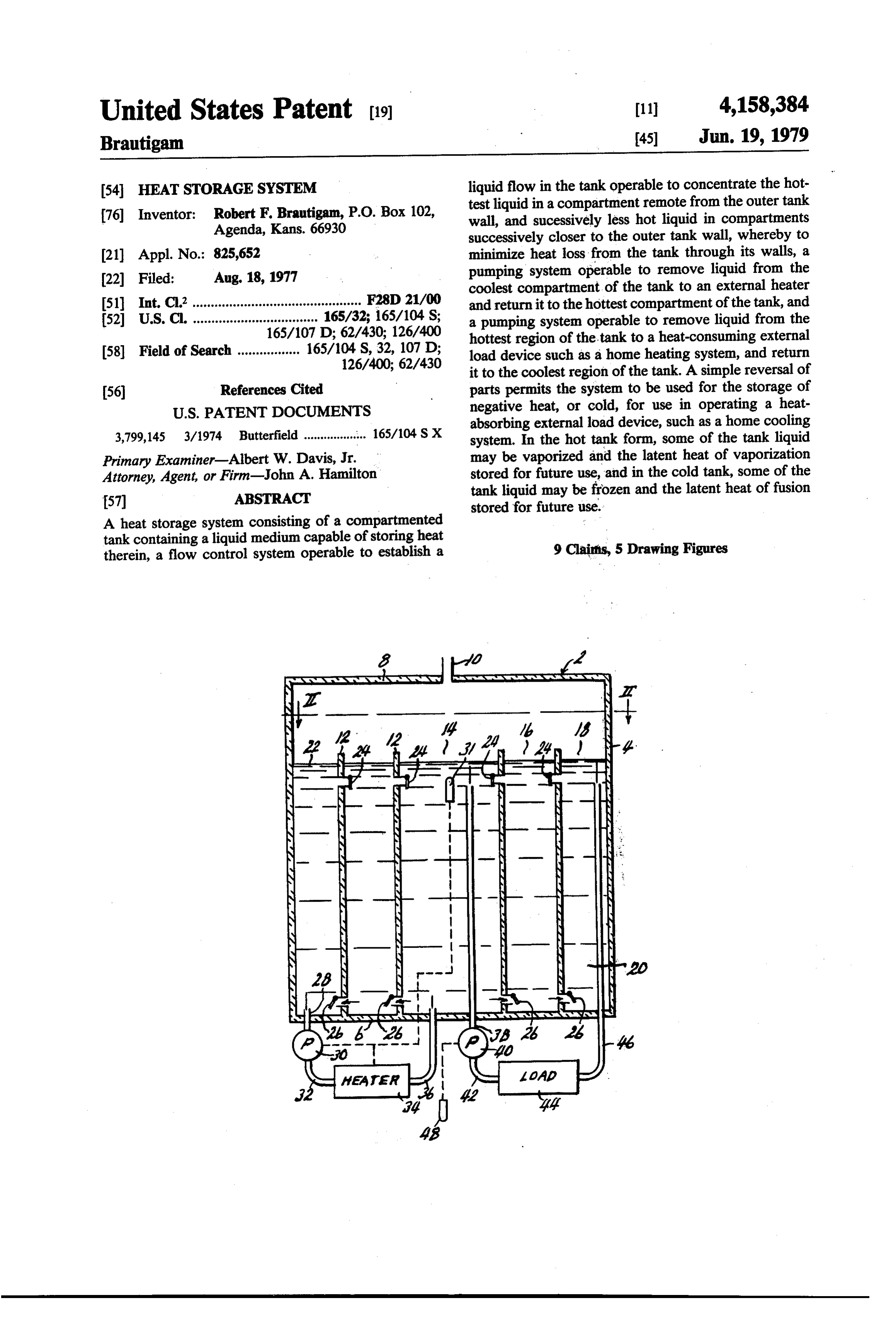
United States Patent (19) 11) 4,158,384 Brautigam 45 Jun. 19, 1979 54 HEAT STORAGESYSTEM liquid flow in the tank operable to concentrate the hot test liquid in a compartment remote from the outer tank 76 Inventor: Robert F. Brautigam, P.O. Box 102, wall, and sucessively less hot liquid in compartments Agenda, Kans. 66930 successively closer to the outer tank wall, whereby to 21 Appl. No.: 825,652 minimize heat loss from the tank through its walls, a (22 Filed: Aug. 18, 1977 pumping system operable to remove liquid from the coolest compartment of the tank to an external heater 51) Int. C.’.............................................. F28D 21/00 and return it to the hottest compartment of the tank, and 52 U.S. C. .................................. 165/32; 165/104 S; a pumping system operable to remove liquid from the 165/107 D; 62/430; 126/400 hottest region of the tank to a heat-consuming external 58) Field of Search ................. 165/104 S, 32, 107 D; load device such as a home heating system, and return 126/400; 62/430 it to the coolest region of the tank. A simple reversal of (56) References Cited parts permits the system to be used for the storage of
absorbing external load device, such as a home cooling 3,799,145 3/1974 Butterfield ................... 165/104 SX system. In the hot tank form, some of the tank liquid Primary Examiner-Albert W. Davis, Jr. may be vaporized and the latent heat of vaporization Attorney, Agent, or Firm-John A. Hamilton stored for future use, and in the cold tank, some of the 57 ABSTRACT tank liquid may be frozen and the latent heat of fusion stored for future use.
A heat storage system consisting of a compartmented tank containing a liquid medium capable of storing heat therein, a flow control system operable to establish a 9 Clairfis, 5 Drawing Figures
Page 2
Drawing sheet — no readable text.
Page 3
Drawing sheet — no readable text.
Page 4
in a "hot" tank, or frozen in a "cold" tank, and the latent
HEAT STORAGESYSTEM heat of vaporization or fusion stored for future use. This invention relates to new and useful improve Other objects are relative simplicity and economy of ments in heat storage systems, and has as its principal construction, and efficiency and dependability of opera object the provision of a means whereby either positive 5 tion. -- - - - - -
or negative heat, that is, temperatures either above or With these objects in view, as well as other objects below atmospheric, may be trapped and stored for fu which will appear in the course of the specification, ture use when needed, said heat being stored in a liquid reference will be had to the accompanying drawing, medium contained in an insulated tank. The system has 10 wherein:
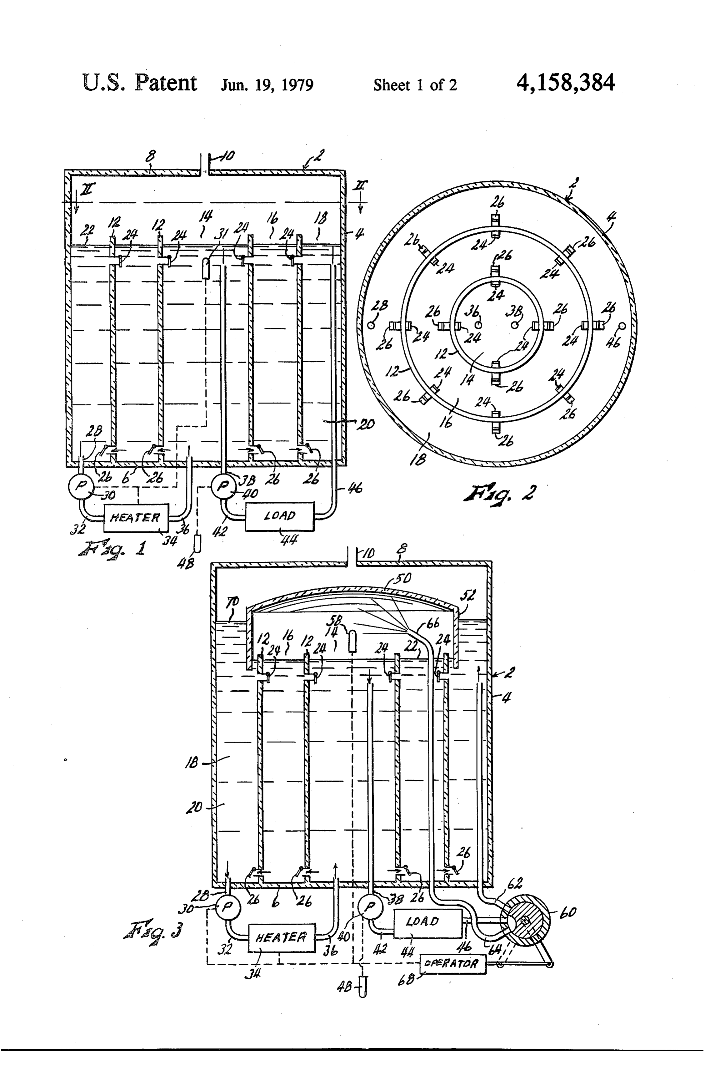
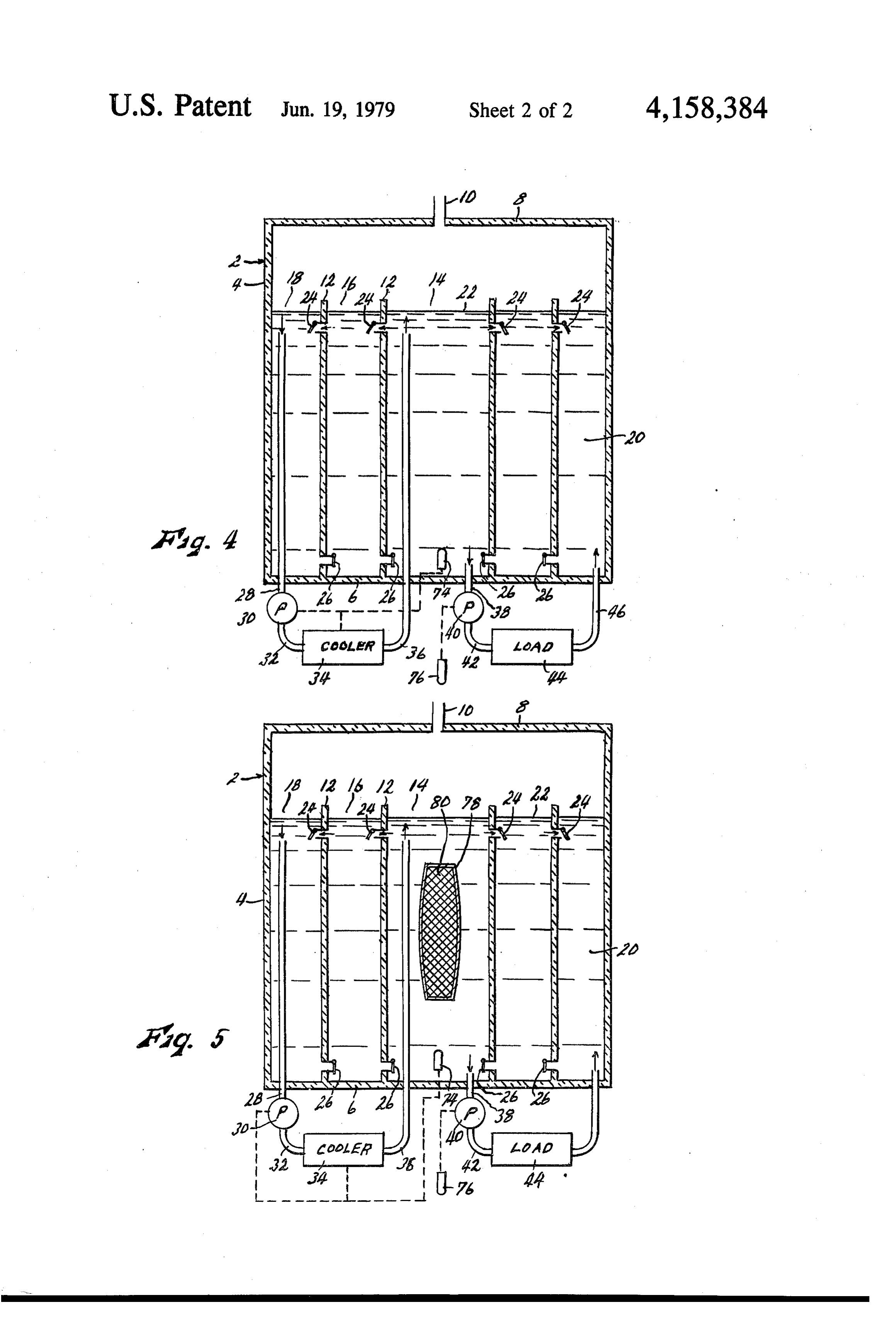
FIG. 1 is a schematic representation of a heat storage been envisioned primarily as an economical system for system embodying the present invention, including a heating and cooling homes or other buildings, although its use is not limited to this function. For this purpose, element sectional vertical view of the tank forming a principal of the system, arranged to store positive heat, the system would usually include both a 'hot' tank for storing a hot liquid to assist in the operation of a home 15 FIG. 2 is a sectional view taken on line II-II of FIG. heating system, and a "cold' tank for storing a cold 1, FIG. 3 is a view similar to FIG. 1, but including liquid to assist in the operation of a home cooling sys means permitting vaporization of a portion of the tank tem. Both the hot and cold tanks may be substantially liquid and storage of the latent heat of vaporization, identical except for a simple reversal of certain elements thereof. Each tank has external input and load flow 20 arranged4 to
FIG. is a view similar to FIG. 1, but with the parts store negative heat, and circuits each operable to circulate liquid from the tank, FIG. 5 is a view similar to FIG. 4, but including respectively through a heating or cooling device, and a means permitting heat-consuming or heat-absorption load device, and and storage of thefreezing latent of a portion of thatank liquid heat of fusion.
return the liquid to the tank. The overall object of the system is that the input devices may operate at a level 25 throughout the several views.apply Like reference numerals to similar parts less than the peak load demand, thereby storing heat or tion include a large tank 2, here shownofasthe All forms inven cold during periods of lesser load demand, for later use vertical cylindrical outer wall 4, a bottom wall 6, and aa having in periods of greater demand. Thus, depending on the top wall 8, although its specific shape is optional. Top storage capacity of the tank, it can supply a home heat wall 8 is provided with an atmospheric vent 10, which ing system, or a home cooling system, for substantial 30 may be suitably hooded when necessary. The interior of periods of time before requiring additional input of heat or cold, and valuable equipment, fuel and energy econo the tank is divided by a plurality of concentric walls 12, extending from bottom wall 6 to an elevation spaced mies may be realized. below top wall 8, into a central compartment 14 and a Another object is the provision of a system of the plurality of annular ring compartments 16 and 18 sur character described wherein the tank is partitioned to 35 rounding central compartment 14 in successively out provide a series of compartments including a central wardly spaced relation therefrom. The outer wall of compartment remotely spaced from the outer tank ring compartment 18 is formed by vertical tank wall 4. walls, and a plurality of additional compartments Walls 12 are shown as cylindrical, although this is op spaced successively closer to the outer tank walls, and tional. All of the tank walls, as well as walls 12, are suitable valves operable to produce gravity and convec 40 preferably insulated as indicated, in order to minimize tion currents of liquid within the tank whereby liquid of heat transfer therethrough.
the most extreme temperature, either hot or cold, from Referring more specifically to FIGS. 1 and 2, which either the input or load returns, will tend to be con diagram a simple form of the system operable to store ducted to and retained in the central compartment, with positive degrees of heat well above atmospheric tem liquid of successively less extreme temperatures being 45 peratures, the tank 2 is charged with a liquid 20 to a conducted to and retained in compartments succes level 22 somewhat below the level of the upper edges of sively outward from said central compartment. In this walls 12. For convenience and clarity, liquid 20 will be manner, the temperature differentials across the com described as water, although it will be readily apparent partment walls, and across the outer wall of the tank, that liquids other than water could be used if desired. are reduced to a minimum, whereby to reduce the quan 50 Each of walls 12 has a plurality of inwardly opening tity of heat transferred through said walls and eventu upper check valves 24 disposed adjacent the upper edge ally lost to the atmosphere. The compartment and tank thereof, below the water level 22 therein, and spaced walls may also be insulated to further reduce such angularly about the periphery thereof, and a plurality of losses. outwardly opening lower check valves 26 disposed A further object is the provision of a system of the 55 adjacent the lower edge thereof, just above the bottom character described wherein the operating temperature wall 6 of the tank, and spaced angularly about the pe differentials at the load and input devices, and also the riphery thereof.
convection flow of liquid in the tank, are assisted by the In an input flow circulating system, water is drawn fact that the input flow circuit withdraws liquid from from the lowermost portion of outermost tank compart the compartment of the tank wherein the liquid temper ment 18 through a pipe 28, and delivered by said pump ature is the least extreme, and returns it to the compart to a heat exchanger 34, which in the case of a "hot' tank ment of the most extreme temperature, while the load is a heater capable of elevating the temperature of the flow circuit withdraws liquid from the tank compart water. Said heater may utilize heat from any available ment of the most extreme temperature, and returns it to source, such as a gas or oil burner, or furnace, or a solar the tank compartment of the least extreme temperature. 65 heat collecting device, or heat which would otherwise A still further object is the provision of a system of be wasted, such as the exhaust from steam engines or the character described wherein is provided means turbines, or heat exhausted from an air conditioning or whereby a portion of the tank liquid may be vaporized refrigeration system. Use of the heat exhaust from an air
Page 5
conditioning system is particularly useful in a combined supplying heat at a sufficiently high temperature, water heating-cooling system for a home, in that heat re in the tank boils and the steam passes off through vent moved from the home during periods of air condition 10, unless a suitable thermostatic control, as described, ing may be captured and stored for use in periods of is provided to shut off the heater before this occurs. The heating demand. Water from heater 34, still driven by 5 concentration of the hottest water in the central tank pump 38, is returned through pipe 36 to the lowermost compartment, with successively cooler water in the portion of central tank compartment 14. In a load flow outer compartments, does much to conserve the heat circulating system, water is drawn from the topmost and prevent loss thereof through the tank walls. The portion of central tank compartment 14 through a pipe temperature differential across each of walls 12, and 38 by an external pump 40, and delivered by said pump 10 across outer tank wall 4, is thus greatly reduced, which through a pipe 42 to a load device 44 in which heat of reduces the amount of heat conducted therethrough, the water is consumed. Said load may, for example, and eventually lost through...the outer tank wall. More constitute the hot water heating system of a house. The compartments than the three actually shown would return water from the load, still driven by pump 40, is increase this saving. With a sufficient number of com carried through a pipe 46 and deposited thereby into the 15 partments, the normal temperature of the water in the topmost portion of outermost tank compartment 18. outermost compartment could be reduced almost to Either or both of pumps 30 and 40 may be operative at atmospheric level, so that there would be very little any given moment, but in any case the amount of water heat loss through outer tank wall 4 even if said wall removed from the tank is returned thereto, and the were not insulated. It is of course important that the amount of water in the tank therefore remains substan 20 combined flow rates of input pump 30 and load pump tially constant. 40, moving through the tank, not be sufficiently high to In operation of the species of the invention shown in interfere materially with convection water currents in FIGS. 1 and 2, the operation of input pump 30 would the tank, since it is these currents, in combination with ordinarily be controlled by suitable thermostatic means the pressure-induced opening and closing of check 31 operable to actuate said pump whenever the maxi 25 valves 24 and 26, which concentrate the hottest water in mum water temperature in the tank, which as will ap each compartment at the top thereof where, as will pear occurs at the surface level of central compartment appear, its heat may best be utilized. For this reason, the 14, falls below a pre-determined level, and to deactuate water capacity of the tank should be very large as com said pump whenever said temperature rises to a prede pared to the pump flow rates. For example, in the use of termined maximum safe level, for example just below 30 the tank in the heating systems of ordinary homes, a the boiling point. The thermostatic means may also tank capacity of at least several thousand gallons is control the operation of heater 34. Whenever pump 30 recommended.
is operative, therefore, water heated by said heater is Operation of load pump 40 would ordinarily be con delivered by pipe 36 to central tank compartment 14, trolled by a suitable thermostatic means 48 operable to wherein the hotter water rises by convection toward 35 actuate said pump whenever load 44 calls for heat. the water level 22, and cooler water sinks toward the Pump 40 has a higher delivery rate than pump 30, and tank bottom. Also, if load pump 40 is not then operating whenever said pump is operating, it draws water from due to lack of load demand for heat, the water level in the top level of central tank compartment 14, which as compartment 14 will rise slightly above the level in previously described always contains the hottest liquid compartment 16, and the pressure differential thus cre present in the tank, delivers it to load 44 wherein heat is ated across wall 12 separating these compartments extracted therefrom, and returns it at a relatively low causes upper check valves 24 of said wall to close, and temperature to the top of outermost tank compartment lower check valves 26 to open, so that the cooler water 18. When the flow rate of pump 40 is less than the input at the bottom of chamber 14 flows outwardly through flow rate of pump 30, which could occur only when the valves 26 into chamber 16. In chamber 16, the process 45 demand for heat is zero, the previously described out repeats itself, the hotter water rising and the cooler ward flow pattern of water in the tank as induced by water sinking, and the water level rising to create a pump 30 will continue. The flow rate of pump 40 ex pressure differential closing upper check valves 24 and ceeds that of pump 30, since an important object of the opening lower check valves 26 in the wall 12 separating system is that a comparatively low but relatively contin compartments 16 and 18, so that the coolest water of 50 uous input flow will store heat in the tank sufficient to chamber 16 flows to chamber 18, where the hotter supply the required heat for the relatively high but less water again rises and the cooler water sinks for removal continuous load flow. The liquid level in outer tank by pump 30. Thus when equilibrium has been estab compartment 18 will thus rise slightly relative to that in lished, the liquid level in the successive compartments compartment 16, causing lower check valves 26 of will be graduated downwardly from the central com 55 outer wall 12 to close, and upper check valves 24 to partment outwardly, and there will be a continuous open to allow the surface water of compartment 18 to water flow from the central compartment to the succes flow into compartment 16, where the process is re sive outer compartments, and through pump 30 and peated to close lower check valves 26 and open upper heater 34 back to the central compartment. The hottest check valves 24 of inner wall 12. Thus the liquid levels water in each compartment will be adjacent the top in the compartments are reversed to grade downwardly level thereof, and the temperature at the top of chamber from the outermost to the central compartment. The 14 will be the highest of all, with general temperatures gradations of water level in the various compartments in the successive outer chambers being successively are very slight, and at no time are the upper check lower. valves 24 ever exposed above the water level. Thus the The temperatures of the water in all of the compart 65 hottest water in each compartment, which of course is ments will continue to rise so long as heater 34 contin at its top, flows inwardly toward the central compart ues to supply heat at a greater rate than is consumed by ment to be available for load use. In this manner, virtu load 44, until, presuming that heater 34 is capable of ally all of the heat carried in the tank water is made
Page 6
available for load use in periods of high demand. At this in an amount equal to the latent heat of vaporization. time, any heat delivered by input pump 30 and heater 34 The steam creates a positive pressure beneath the dome, is trapped in the central compartment, and is also avail lowering the liquid level therebeneath by forcing liquid able for immediate load use. Whenever the demand outwardly through lower check valves 26, and elevat ceases, as signalled by thermostat 48 to deactuate load ing the water level in outermost tank compartment 18, pump 40, the previously described radially outward as indicated at 70. The latent heat trapped in the steam flow of water in the tank, as produced by input pump represents a significant additional supply of heat availa 30, will be resumed and will continue, thus depositing ble for later load use. The elevation of the water level additional heat in the tank, unless and until the tank outside of the dome also applies fluid pressure to the temperature is sufficiently high that thermostat 31 deac O water within the dome. This raises the boiling point of tuates input pump 30 and heater 34. the water, and hence increases the volume of heat As just described, the form of the system shown in which must be added thereto before its boils and vapor FIGS. 1 and 2 is prevented from vaporizing the tank izes. This further increases the total heat storage capac water by thermostat 31, which is set to deactuate the ity of the tank. When the steam pressure inside of the heat input at a maximum tank water temperature at least 15 dome rises to the pre-set control level of pressurestat 58, slightly below its boiling point. Any vaporization of the said pressurestat functions to deactuate pump 30 and/or water would simply generate steam which would be heater 34, and to move valve 60 to its illustrated second lost to atmosphere at vent 10, and would represent position, to direct the return load flow to nozzle 66. The wasted energy. FIG. 3, however, shows a modification control pressure of pressurestat 58 is set to allow only a of the system which permits vaporization of some of the 20 permissable elevation of the water level 70 in outermost tank water, and the retention and storage of the large tank compartment 18, since higher dome pressures amount of latent heat required to produce said vaporiza would allow water to be blown through vent 10, or tion. This provision greatly increases the heat storage steam to pass under the skirt 52 of the dome and hence capacity of a tank of any given liquid capacity. to the vent, which would represent a waste of energy. The FIG. 3 species is substantially identical to that of 25 Then, if the load circuit has been actuated by thermo FIG. 1, except for certain modifications. It is provided stat 48, or is later so actuated, the return flow from load with a heat shield dome 50 disposed within tank 2, cov 44 is directed by valve 60 to nozzle 66, and is sprayed ering all of the tank compartments except outermost into the dome. Being cooler than the steam in the dome, compartment 18, and is provided with a cylindrical skirt it absorbs heat therefrom, including and taking advan 52 which loosely surrounds outermost wall 12 and 30 tage of the latent heat stored therein, and falls back into projects downwardly sufficiently to extent beneath tank tank compartments 14 and 16, where it rejoins the flow liquid level 22 at all times. The dome may be insulated, currents of the tank at the most advantageous points, as shown. It is fixed in the tank by any suitable means, that is, at the tops of the associated tank compartments, not shown. The heat input system, consisting of pump in position to flow to the central compartment through 30 and heater 34, instead of being controlled by a ther 35 upper check valves 24 in the normal load flow pattern mostat as at 31 of FIG. 1, is controlled by a pressure of the tank. It should be understood, however, that the sensitive device, or "pressurestat' 58 disposed within use of transfer valve 60 and nozzle 66, while desirable in dome 50 above liquid level 22, and operable to deactu that it provides a faster recovery of the latent heat of ate pump 30 and/or heater 34 whenever the vapor pres any steam trapped in the dome, is optional only. The sure under the dome exceeds a pre-determined positive heat content of the steam in the dome would eventually pressure. The load return pipe 46 is connected to a be returned to the tank liquid even in the absence of two-position valve 60 which in one position directs the these elements, as the tank liquid is cooled by the heat return water to outermost tank compartment 18 removed therefrom at load 44. through pipe 62, and in a second position, as illustrated, FIG. 4 shows a modification of the system adapted to directs the return water through a pipe 64 to a spray 45 store "negative heat", or coldness, whereby to assist in nozzle 66 disposed within dome 50 above water level the operation of heat-absorbing load devices. Its ar 22. Valve 60 is controlled by a valve operator 68 also rangement is generally similar to FIG. 1, with certain subject to pressurestat 58, so as to retain said valve in its modifications. In this case, heat exchanger 34 consti first position so long as the dome pressure remains tutes a cooling device, or cooler, such as a refrigeration below the preset control pressure of the pressurestat, 50 unit, whereby the temperature of the water is reduced, and to move said valve to its illustrated second position and load 44 constitutes a heat absorption device, such as whenever the dome pressure reaches or exceeds said aupper fluid-operated home air conditioning system. Also, check valves 24 open outwardly, lower check control pressure. valves 26 open inwardly, intake pipe 28 and delivery As long as the maximum water temperature within the tank remains below the boiling point, the operation 55 pipe 36 of the cooler extend adjacent the water level 22 of the FIG. 3 species is substantially identical to that of in the tank, and intake pipe 38 and delivery pipe 46 of FIG. 1, the input flow generated by pump 30 passing load 44 open into the bottom of compartments 14 and through heater 34 to the central tank compartment, and 18, all of which are substantial reversals from the condi radially outwardly through the tank compartments to tions of FIG.1. The operation of pump 30 and cooler 34 return to pump 30, while the load flow of pump 40, isbottom controlled by a thermostat 74 disposed adjacent the of tank compartment 14, where as will appear, when required, proceeds through load 44 and valve 60 (then in its first position) to the outermost tank compart the coldest water of the tank is always concentrated, ment then radially inwardly through the tank compart said thermostat being operable to actuate said pump and ments to return to pump 40. However, in periods of no 65 cooler whenever the water temperature rises above a heat demand by the load, the maximum water tempera pre-determined maximum useful level, and to deactuate ture in the central tank compartment may rise to the said pump and cooler whenever the water falls to a boiling point. As heat is further added, a portion of the predetermined minimum level the latter level being water is converted to steam, as it absorbs additional heat slightly above the freezing point to prevent any freezing
Page 7
of the tank water. The load pump is actuated by a ther FIG. 5 shows a modification of the species of the mostat 76 whenever load 44 requires the extraction of system of FIG. 4 which permits the freezing of a quan heat. tity of water, whereby to increase the cold storage In operation of the FIG. 4 species, it will be seen that capacity of the tank by an amount equal to the latent cold water flowing from cooler 34 is delivered to the 5 heat of fusion of the ice. The FIG. 5 species is identical top of central tank compartment 14 by pipe 36. In said to that of FIG. 4 except that a sealed or encapsulated compartment, the colder water sinks and the warmer tank 78 containing water (or ice) 80 is supported in water rises by convection, and the water level in com central tank compartment 14 by any suitable means, not partment 14 rises slightly to open upper check valves 24 shown. The liquid 20 which circulates in tank 2 may be of inner wall 12, to allow the warmer top water to flow 10 the brine or water-alcohol mixture previously men outwardly to chamber 16, where the process repeats tioned. Tank 78 is flexibly expansible to accomodate the itself to concentrate the colder water at the bottom and expansion of the ice as it freezes. warmer water at the top, and raise the water level In operation of the FIG. 5 species, it will be seen that slightly to open the upper check valves 24 of outer wall the cold liquid delivered by pump 30 to the top of com 12 to pass the warmer water to chamber 18, where the 15 partment 14 and passing downwardly around tank 78 convection separation of the colder and warmer water will eventually cool the water in tank 78 to the freezing again occurs and the warmer water is returned to pump point, and additionally remove the latent heat of fusion 30 for further cooling by cooler 34. On the other hand, therefrom to convert it to ice. On the other hand, the when water is returned to the bottom of outermost warmer load return liquid, circulating upwardly in compartment 18 by load pump 40, cooler water sinks to 20 compartment 14 as already described, will transfer heat the bottom of the compartment and warmer water rises into tank 78, in an amount equal to the latent heat of by convection, and the water level is raised slightly to fusion, and hence be cooled, before the ice melts. The open lower check valves 26 of outer wall 12 to allow latent heat of fusion is sufficiently greater, in proportion the coldest water to pass into compartment 16, where 25 atoheat the water volume, to constitute the water in tank 78 sump of significant capacity into which the load the process repeats itself with the coldest water eventu heat may be dispersed, thereby increasing the cold stor ally being deposited in the lower portion of central age capacity of tank 2 and reducing peak loads on compartment 14 for return to load 44 by pump 40. Thus the "input' pump 30 tends to produce a radially out cooler 34. Tanks 78 could also be placed in compart ments outwardly from central compartment 14, if de wardly flow of water in the tank, while the load pump 30 sired, so long as the temperature of liquid 20 in said 40 tends to produce a radially inward flow in the tank, outer compartments which is the same as in FIG. 1, although the flows are water. However, it iswas sufficiently low to freeze the reversed as to the upper and lower portions of the tank, tion to minimize the temperatureobject an important of the inven differential across and the actual direction of flow depends on which flow outer tank wall 4, whereby to minimize entry of exterior is larger at any given time. Since the flow rate of pump 35 heat into the system. For this reason, thermostat 74 40 is normally greater than the flow rate of pump 30, the functions to deactuate the cooler, and hence to preserve radially inward load flow prevails whenever pump 40 is operative. The coldest water is always concentrated at the desired upward temperature gradient from central the lower portion of central compartment 14, and the compartment likely nor 14 outwardly. Therefore, it is neither desirable that the temperature of liquid 20 in coldest water from the other compartments is always the outermost compartments available to flow to the central compartment through ciently low to freeze water of tank 2 would be suffi encapsulated therein. of check valves 26 in periods of high load demand.
Presuming that cooler 72 is capable of producing ments, freezing could be permitted in a greatercompart course, if tank 2 contained a greater number of number sub-freezing temperatures, it will be apparent that in of the more central compartments.
periods of low or zero cooling load demand, the water 45 While I have shown and described certain specific in central compartment 14 could be frozen. Although the water temperature is normally lowest at the bottom embodiments ent that many of my invention, it will be readily appar minor changes of structure could be made of compartment 14, the freezing would start at the without departing from the spirit of the invention. water surface 22 of this compartment due to the phe What I claim as new and desire to protect by Letters nomenon that water expands as it approaches the freez 50 Patent is:
ing point, and therefore is reduced in specific gravity 1. A heat storage system comprising: and rises to the surface. Such freezing cannot be al a. a tank containing a liquid and provided with inte lowed since it would interfere with the described con rior walls dividing it into a central compartment vection and gravity flow patterns of the water. Thermo and a plurality of generally annular compartments stat 74 is hence set to deactuate pump 30 and cooler 34 55 horizontally encircling said central compartment, before the water is cooled to the level at which its pre said compartments being open at their tops and said freezing expansion commences. Of course, however, tank being vented to atmosphere at its top, the while liquid 20 has for convenience been described as warmest liquid in each compartment tending to rise water, said liquid is preferably a brine, water-alcohol and the coolest liquid to sink by virtue of convec mixture or other liquid having a much lower freezing 60 tion currents therein, point than water. In this manner, the "cold” storage . check valves mounted in each of said interior walls capacity of the tank is greatly increased. The setting of below the liquid level of said tank and respectively thermostat 74 would then be changed to cut off the inlet adjacent the liquid level and bottom of said tank, flow at a much lower temperature, although said cut-off each of said check valves being operable to permit temperature is preferably maintained sufficiently high 65 the flow of liquid through the associated wall in that the temperature in outermost compartment 18 is one direction only, the upper and lower check sufficiently high to minimize any heat absorption valves being operable to permit flow in respec through outer tank wall 4. tively opposite directions,
Page 8
c., a heat exchanger device exterior to said tank, vate the boiling point thereof to increase the tempera d. a heat load device exterior to said tank, ture required to vaporize it, whereby to increase the e, an input flow system operable to withdraw liquid heat storage capacity thereof, and said vapor serving to from the outermost compartment of said tank, pass store the latent heat of vaporization added thereto to it to said heat exchanger device whereby its tem- 5 vaporize it.
perature is changed, and return it to said central 5. A system as recited in claim 4 with the addition of tank compartment, and a pressure-sensitive control device disposed within said f, a load flow system operable to withdraw liquid dome and operable to deactuate said input flow system from the central tank compartment, pass it to said whenever the vapor pressure within said dome exceeds heat load device wherein its temperature is oppo- 10 a predetermined level, whereby to prevent liquid being sitely changed, and return it to the outermost tank elevated in said outer compartment by said pressure, or compartment, said check valves opening in direc vapor passing beneath the dome skirt, from escaping tions to permit the flow of liquid of the temperature through said tank vent.
closest to the output temperature of said heat ex 6. A system as recited in claim 5 with the addition of changer from the outermost to the central com- 15 a two-position transfer valve disposed in said load flow partment, and the flow of liquid of the temperature system, being operable in a first position to deliver the farthest from the output temperature of said heat return load liquid to the outermost compartment of the exchanger from the central to the outermost com tank, and in a second position to deliver said return partment, whereby whenever said input flow ex liquid to a spray nozzle disposed within said dome, said ceeds said load flow, the general flow of liquid in 20 valve being operated by said pressure-sensitive control the tank is from the central to the outermost tank to be in said first position whenever said input flow compartment, and whenever said load flow ex system is actuated, and to be in said second position ceeds said input flow, the general flow of liquid in whenever said input flow system is deactuated. the tank is from the outermost to the central tank 7. A system as recited in claim 1 wherein said heat compartment, the flow rate of said load flow sys- 25 exchanger constitutes a liquid cooler, and said load tem, when said system is actuated, being greater constitutes a heat-absorption device, and wherein said than the flow rate of said input flow system. upper check valves open outwardly and the lower of 2. A system as recited in claim 1 wherein said heat said check valves open inwardly.
exchanger constitutes a heater and said load constitutes 8. A system as recited in claim 7 wherein said liquid a heat-removing device, and wherein the upper of said 30 cooler is capable of producing liquid temperatures suffi check valves open inwardly and the lower of said check ciently low to freeze said liquid, and with the addition valves open outwardly. of a thermostatic control operable responsively to the 3. A system as recited in claim 2 wherein said heater lowest liquid temperature within said tank to deactuate is capable of producing liquid temperatures capable of said input flow system before said lowest tank liquid vaporizing said liquid, and with the addition of thermo-35 temperature falls to its freezing point. static control means operable to deactuate said input 9. A system as recited in claim 8 with the addition of flow system whenever the maximum liquid temperature a capsule tank disposed within at least the central com within said tank rises sufficiently to approach said va partment of said tank, said capsule tank containing a porization temperature. liquid having a freezing point higher than that of the 4. A system as recited in claim 2 wherein said heater 40 tank liquid, and higher than the control temperature of is capable of producing liquid temperatures capable of said thermostatic control, whereby said capsule tank vaporizing said liquid, and with the addition of a heat liquid may be frozen during periods when the load flow shield dome mounted in said tank to cover at least said system is deactuated, and melted by warmer tank liquid central compartment in spaced relation above the liquid circulated around said capsule tank during periods level therein, and having a skirt depending beneath the 45 when said load flow system is actuated, in order that liquid level in a relatively outwardly spaced compart said load flow system may deposit its return heat into ment, whereby vapor produced at the liquid level in said capsule tank liquid in an amount equal to the latent said central compartment collects in said dome to create heat of fusion necessarily removed from said capsule a positively elevated vapor pressure, said pressure ele tank liquid to freeze it, and hence reduce the operating vating the tank liquid level outside of said dome to 50 load on said cooler. k k pressurize the liquid within the dome, whereby to ele K k
Provenance
- Collection
- Cited prior art
- Original PDF
- patentimages.storage.googleapis.com →
- Filed
- 1977-08-18
- Pages
- 8
- Method
- pdftotext (the PDF's own text layer) + pdftoppm 300dpi page scans
- Source
- Google Patents bibliographic record
- Granted
- 1979-06-19
- Inventors
- Robert F. Brautigam
- Transcribed from
- patentimages.storage.googleapis.com →