patent · US4541397
Gaseous fuel carburetion system
17 September 1985
Page 1 — bibliographic record
United States Patent (19) 11 Patent Number: 4,541,397 Young 45) Date of Patent: * Sep. 17, 1985 (54) GASEOUS FUEL CARBURETION SYSTEM Primary Examiner-E. Rollins Cross Attorney, Agent, or Firm-Fetherstonhaugh & Co.
75 Inventor: Colin G. Young, Mississauga, Canada (73) Assignee: Enco Wheaton (International) 57 ABSTRACT Limited, Toronto, Canada In a gaseous fuel carburetion system in which air and * Notice: The portion of the term of this patent gaseous fuel are mixed in a mixer prior to induction into subsequent to May 22, 2001 has been an internal combustion engine, and in which the rate of disclaimed. flow of the induction air is controlled by throttling the 21 Appl. No.: 605,278 intake of the air/fuel mixture, and in which gaseous fuel is supplied to the system from a pressurized source, an 22 Filed: Apr. 30, 1984 improved method and apparatus for regulating the sup ply of gaseous fuel to the air/fuel mixer is provided.
Related U.S. Application Data The method comprises the steps of sensing at least one 63 Continuation of Ser. No. 371,469, Apr. 23, 1982, Pat. operating parameter of the engine which is a function of No. 4,449,509. the induction air flow rate and generating a control signal which varies in response to changes in the induc (51) Int. Cl. ............. a a saw A & & & 8& w w a ew ow FO2B 43/00 tion air flow rate, controlling the rate of flow of the (52) U.S. Cl. ............. - -- - - - - - - -- - - 123/527; 123/27 GE;
gaseous fuel from the source to the mixer by means of 123/577; 123/525; 48/180 P said control signal whereby the rate of flow of the gase 58) Field of Search . - a -- a a a 123/527, 525, 27 GE, ous fuel varies in response to the sensed changes in the 123/577; 48/180.1, 189.1 parameters related to the air flow rate. The apparatus 56) References Cited comprises; mixer means arranged to receive and mix the
1,932,370 10/1933 Heinish ............................... 123/527 the mixture to the engine, sensing means for monitoring 3,540,419 11/1970 Fox ........ ... 123A27 GE at least one operating parameter of the engine which is 3,960,126 6/1976 Shinoda ............................... 23/527 a function of the induction air flow rate and generating 4,063,905 12/1977 Johnson et al. ..................... 123/527 a control signal which varies in response to changes in 4,141,326 2/1979 Wolber ......... ... 123/DIG. 12 the induction air flow rate, flow control means adapted 4,149,562 4/1979 Johnson ............................ 26/44 A to control the rate of flow of the gaseous fuel from the 4,227,497 10/1980 Mathieson . ... 123/525 source to the mixer whereby the rate of flow of the 4,308,843 1/1982 Garretson ..... ... 123/527 gaseous fuel varies in response to the sensed changes in
the parameters related to the air flow rate.
FOREIGN PATENT DOCUMENTS
1370619 4/1974 United Kingdom .......... 123/27 GE 6 Claims, 4 Drawing Figures
AIR CLEANER
EVAPORATOR
& PRESS. REG.
ENGINE
Page 2
Drawing sheet — no readable text.
Page 3
Drawing sheet — no readable text.
Page 4
Drawing sheet — no readable text.
Page 5
whereby the rate of flow of the gaseous fuel varies in
GASEOUS FUEL CARBURETION SYSTEM response to the sensed changes in the parameters related to the air flow rate.
RELATED APPLICATIONS According to a further aspect of the present inven This application is a continuation of application Ser. tion, there is provided in a gaseous fuel carburetion
No. 371,469 filed Apr. 23, 1982, now U.S. Pat. No. system in which air and gaseous fuel are mixed in a 4,449,509. mixer prior to induction into an internal combustion engine, and in which the rate of flow of the induction air
FIELD OF INVENTION is controlled by throttling the intake of the air/fuel This invention relates to a method and apparatus for O mixture, and in which gaseous fuel is supplied to the supplying a gaseous fuel/air mixture to an associated system from a pressurized source, an improved method internal combustion engine. of regulating the supply of gaseous fuel to the air/fuel
PRIOR ART
mixer comprising the steps of regulating the pressure of the gaseous fuel supply to a predetermined pressure
In prior gaseous fuel carburetion systems the fuel is 15 above the induction air pressure thereby to provide a supplied to the mixing device at a pressure slightly positive pressure gaseous fuel supply, sensing at least below atmospheric pressure, the mixer utilizing the one operating parameter of the engine which is a func flow of the induction air to create a depression to induce tion of the induction air flow rate and generating a flow of the gaseous fuel into the mixer. control signal which varies in response to changes in the When such a prior system has been used to modify an 20 induction air flow rate, controlling the rate of flow of existing engine having a carburetion system for liquid the gaseous fuel from the source to the mixer by means fuel such as gasoline, it has been customary to replace of said control signal whereby the rate of flow of the the original air cleaner with a manifold, mixer and a gaseous fuel varies in response to the sensed changes in new air cleaner or alternatively modify the gasoline the parameters related to the air flow rate. carburetor by adding a venturi device. Many different 25 According to yet another aspect of the present inven manifolds are required for the various types of engines tion there is provided in a gaseous fuel carburetion used in vehicles due to hood clearance problems. Per system in which a mixture of air and gaseous is inducted formance and economy of converted vehicles when into an internal combustion engine, and in which the running on gasoline are often impaired and the modifi cation frequently upsets the exhaust emission levels 30 rate of flow of the mixture, and thus the air, is con trolled by throttling the intake of the mixture, the im necessitating rectification and possible vehicle modifi provement of mixer means arranged to receive and mixe cations to obtain statutory approval.
I have found that it is possible to provide a gaseous the induction air and the gaseous fuel supply and to deliver the mixture to the engine, regulator means in the fuel carburetion system which is suitable for the conver gaseous fuel supply line for supplying gaseous fuel to sion of gasoline driven vehicle engines and which does 35 the system at a pressure above that of the induction air not affect the performance, economy or emissions of the converted engine when it is running on gasoline and supply, thereby to provide a positive pressure gaseous fuel supply, sensing means for monitoring at least one does not require the original air cleaner to be replaced. operating parameter of the engine which is a function of I have further found that the flow of gaseous fuel to the mixer may be effectively controlled by regulating it 40 the induction air flow rate and generating a control in response to changes in the air induction flow rate. signal which varies in response to changes in the induc My method of regulating the supply of gaseous fuel tion air flow rate, flow control means adapted to con provides gaseous fuel carburetion for an internal com trol the rate of flow of the gaseous fuel from the source bustion engine. The method includes mixing the gase to the mixture whereby the rate of flow of the gaseous ous fuel with air and supplying the mixture to the en 45 fuel varies in response to the sensed changes in the gine, sensing at least one operating parameter of the parameters related to the air flow rate. engine related to the induction air flow rate, supplying The invention will be more clearly understood after gaseous fuel at a greater pressure than the inconing air reference to the following detailed specification read in and controlling the rate of flow of the incoming gaseous conjunction with the drawings wherein: fuel in response to sensed changes in the parameters 50 FIG. 1 is a diagrammatic illustration of a gaseous fuel related to the air flow rate. carburetion system in accordance with an embodiment of the present invention;
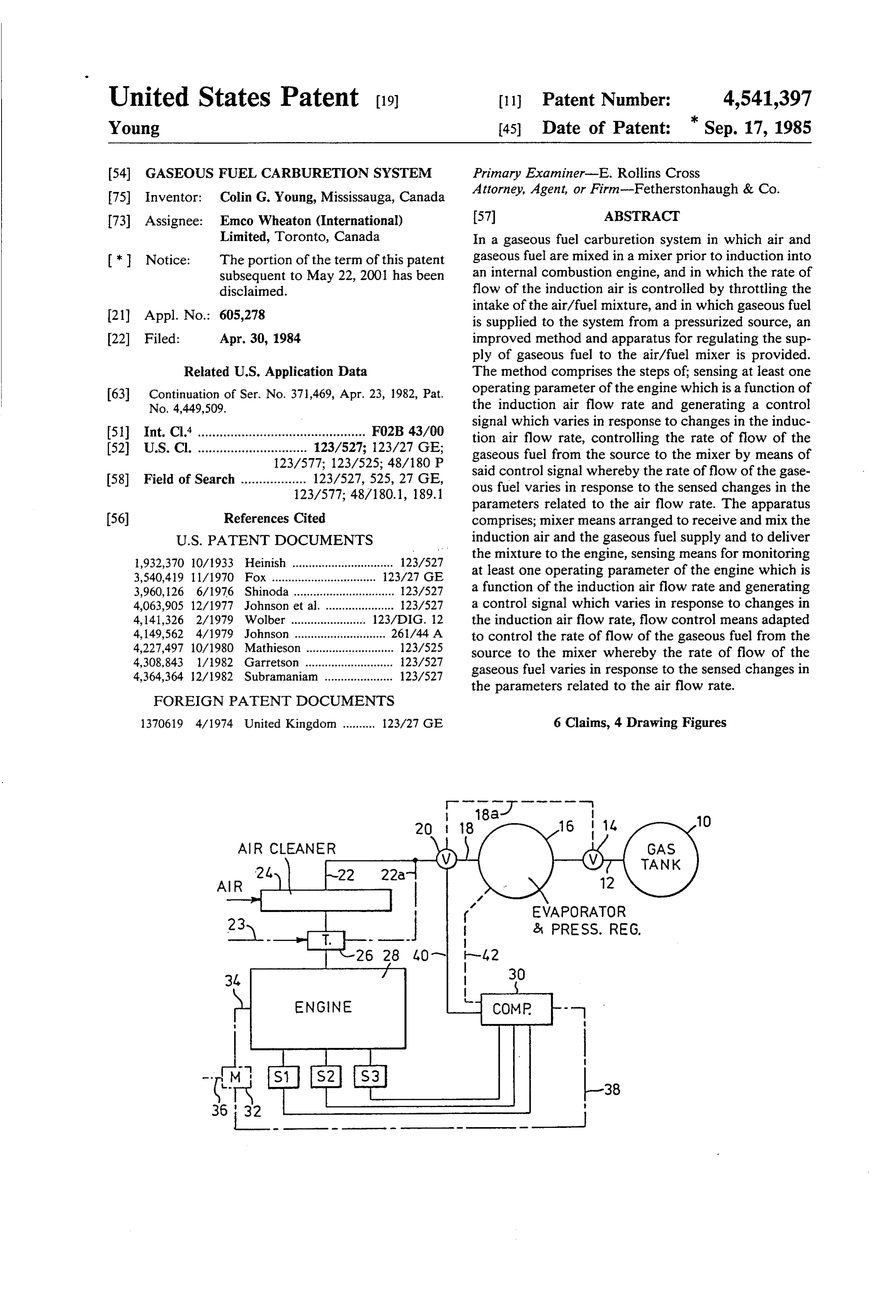
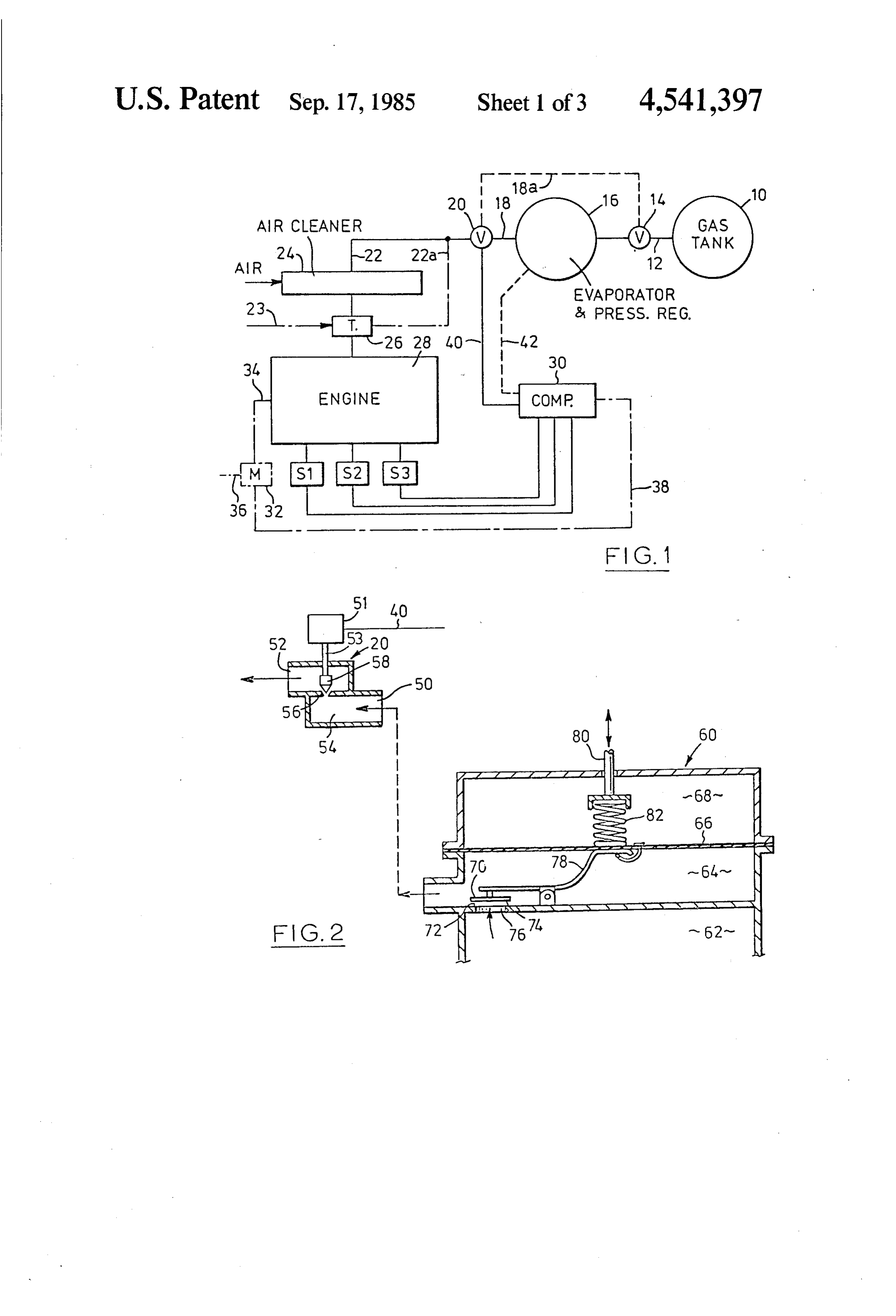
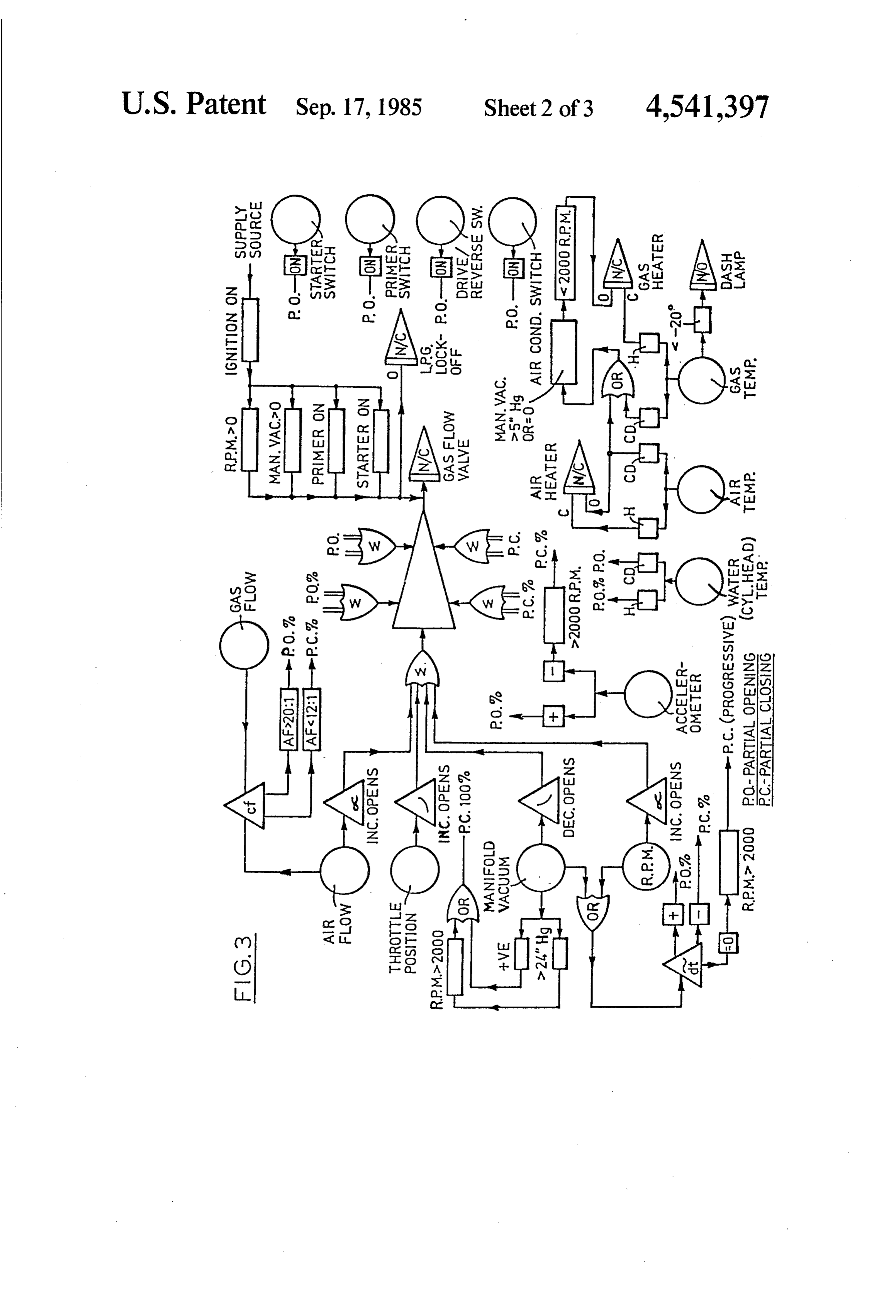
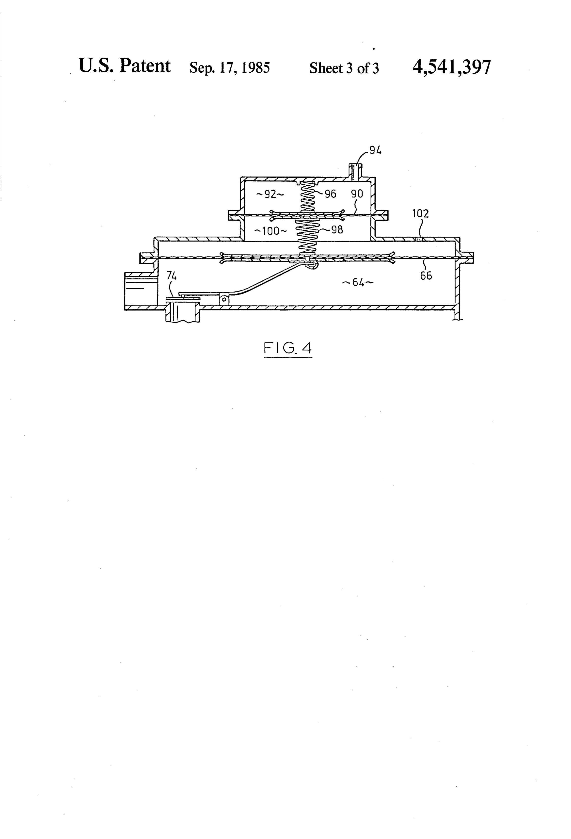
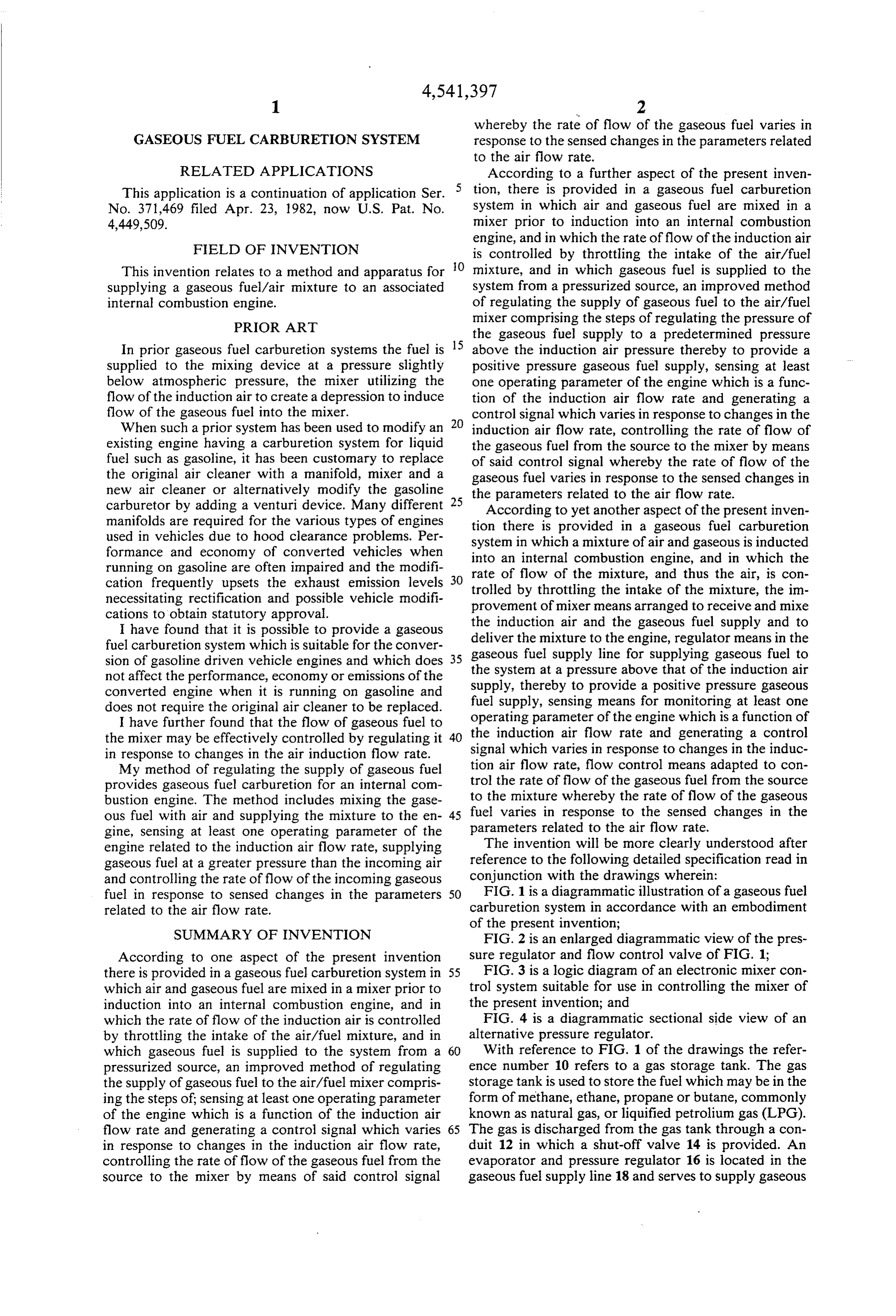
SUMMARY OF INVENTION FIG. 2 is an enlarged diagrammatic view of the pres According to one aspect of the present invention sure regulator and flow control valve of FIG. 1; there is provided in a gaseous fuel carburetion system in 55 FIG. 3 is a logic diagram of an electronic mixer con which air and gaseous fuel are mixed in a mixer prior to trol system suitable for use in controlling the mixer of induction into an internal combustion engine, and in the present invention; and which the rate of flow of the induction air is controlled FIG. 4 is a diagrammatic sectional side view of an by throttling the intake of the air/fuel mixture, and in alternative pressure regulator.
which gaseous fuel is supplied to the system from a 60 With reference to FIG. 1 of the drawings the refer pressurized source, an improved method of regulating ence number 10 refers to a gas storage tank. The gas the supply of gaseous fuel to the air/fuel mixer compris storage tank is used to store the fuel which may be in the ing the steps of sensing at least one operating parameter form of methane, ethane, propane or butane, commonly of the engine which is a function of the induction air known as natural gas, or liquified petrolium gas (LPG). flow rate and generating a control signal which varies 65 The gas is discharged from the gas tank through a con in response to changes in the induction air flow rate, duit 12 in which a shut-off valve 14 is provided. An controlling the rate of flow of the gaseous fuel from the evaporator and pressure regulator 16 is located in the source to the mixer by means of said control signal gaseous fuel supply line 18 and serves to supply gaseous
Page 6
fuel to the system at a pressure above that of the induc rotational speed and the induction manifold pressure or tion air supply thereby to provide a positive pressure vacuum. Hence, preferably the parameters which are gaseous fuel supply. A flow control valve 20 receives sensed by sensing devices S1, S2 are those relating to the gaseous fuel from the line 18 and controls the flow the engine induction manifold vacuum and the rota of gaseous fuel to the line 22. The air cleaner 24 acts as 5 tional speed of the engine. The sensing means S1 may be a mixer which receives gaseous fuel from the line 22 and in the form of a vacuum sensing means associated with induction air and serves to mix the gaseous fuel and the engine induction manifold for sensing the instanta induction air. The mixture of air and gaseous fuel is then neous vacuum in the manifold. The vacuum sensing transmitted through a throttle device 26 to the engine means may be operable either mechanically, pneumati 28. A plurality of sensing devices S1, S2 and S3 are O cally or electronically or by a combination of these provided for sensing a number of operating parameters modes. For example, the induction manifold may be in of the engine. The signals generated by the sensing communication with the chamber which is provided devices S1, S2 and S3 are transmitted to a computer with a pressure transducer operative to generate an device 30. The computer device 30 is preferably in the electrical signal indicative of the pressure in the mani form of a micro-processor suitably programmed so as to 15 fold. This electrical signal can then be used either di be operative to continuously calculate the air flow rate rectly or through the computer device 30 for the pur from the instantaneous values of the signals generated poses of controlling the operation of the flow control by one or more of the sensing devices S1, S2 and S3. valve 30 thereby controlling the rate of flow of the In addition to the sensing devices S1, S2 and S3 a gaseous fuel. The sensing means preferably includes a monitoring device 32 may be provided. The monitoring second sensing means S2 which also serves to control device 32 may be connected to other engine parameters the operation of the flow control valve 20. The sensing by way of line 34 and/or by way of line 36 to any other device S2 is provided for the purposes of sensing an variable which may effect engine performance or en engine parameter which is related to the rotational gine fuel requirements. The monitor device 32 is con speed of the engine. The sensing device S2 may be nected to the computer 30 through lines 38. The com 25 mechanically, pneumatically or electronically operated puter 30 generates a signal which is transmitted to the or a combination thereof. For example, the sensing control valve 20 through the line 40 and/or to the regu device S2 may be in the form of a centrifugal device lator 16 through the line 42. It will be apparent that it is that moves in response to changes in the rotational possible to control the fuel flow by means of either a speed of the engine and the movement of the centrifugal flow control valve 20 or the pressure regulator 16, in device may be utilized in controlling the operation of the preferred embodiment only the flow control valve the flow control valve 20. Alternatively, an impellor 20 is regulated. may be used to provide a pneumatic signal in response The gaseous fuel which is discharged from the evapo to changes in the rotational rate of the engine. In yet rator passes to the flow control valve 20 and the flow of another alternative the sensing device may measure the gaseous fuel from the flow control 20 is regulated by the 35 rotational speed of the engine by counting the pulses in output signal from the computer device 30 so that the the ignition system by electronic means and generating gaseous fuel is admitted to the mixer 24 at the required a signal which is indicative of the rotational speed of the flow rate. The gaseous fuel and air are mixed in the air engine.
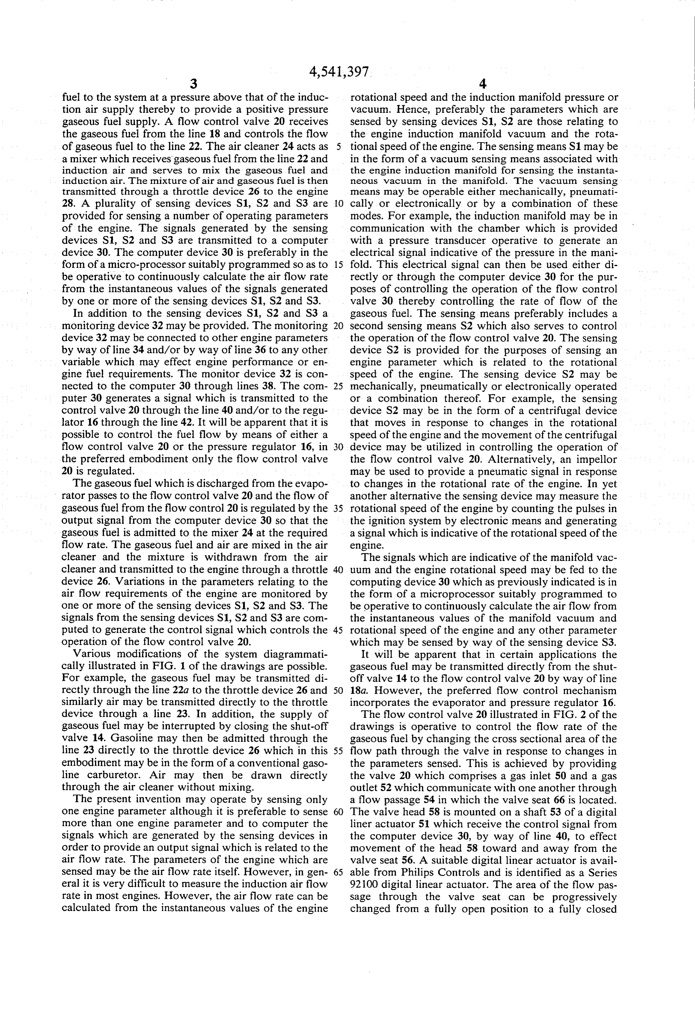
cleaner and the mixture is withdrawn from the air The signals which are indicative of the manifold vac cleaner and transmitted to the engine through a throttle 40 uum and the engine rotational speed may be fed to the device 26. Variations in the parameters relating to the computing device 30 which as previously indicated is in air flow requirements of the engine are monitored by the form of a microprocessor suitably programmed to one or more of the sensing devices S1, S2 and S3. The be operative to continuously calculate the air flow from signals from the sensing devices S1, S2 and S3 are com the instantaneous values of the manifold vacuum and puted to generate the control signal which controls the 45 rotational speed of the engine and any other parameter operation of the flow control valve 20. which may be sensed by way of the sensing device S3. Various modifications of the system diagrammati It will be apparent that in certain applications the cally illustrated in FIG. 1 of the drawings are possible. gaseous fuel may be transmitted directly from the shut For example, the gaseous fuel may be transmitted di off valve 14 to the flow control valve 20 by way of line rectly through the line 22a to the throttle device 26 and 18a. However, the preferred flow control mechanism similarly air may be transmitted directly to the throttle incorporates the evaporator and pressure regulator 16. device through a line 23. In addition, the supply of The flow control valve 20 illustrated in FIG. 2 of the gaseous fuel may be interrupted by closing the shut-off drawings is operative to control the flow rate of the valve 14. Gasoline may then be admitted through the gaseous fuel by changing the cross sectional area of the line 23 directly to the throttle device 26 which in this 55 flow path through the valve in response to changes in embodiment may be in the form of a conventional gaso the parameters sensed. This is achieved by providing line carburetor. Air may then be drawn directly the valve 20 which comprises a gas inlet 50 and a gas through the air cleaner without mixing. outlet 52 which communicate with one another through The present invention may operate by sensing only a flow passage 54 in which the valve seat 66 is located. one engine parameter although it is preferable to sense 60 The valve head 58 is mounted on a shaft 53 of a digital more than one engine parameter and to computer the liner actuator 51 which receive the control signal from signals which are generated by the sensing devices in the computer device 30, by way of line 40, to effect order to provide an output signal which is related to the movement of the head 58 toward and away from the air flow rate. The parameters of the engine which are valve seat 56. A suitable digital linear actuator is avail sensed may be the air flow rate itself. However, in gen 65 able from Philips Controls and is identified as a Series eral it is very difficult to measure the induction air flow 92100 digital linear actuator. The area of the flow pas rate in most engines. However, the air flow rate can be Sage through the valve seat can be progressively calculated from the instantaneous values of the engine changed from a fully open position to a fully closed
Page 7
position. To achieve this the valve head 58 is conical in pressure supplied to the flow valve by opening the shape and arranged to engage the seat at or adjacent the pressure valve.
portion thereof of largest diameter so that progressive For any combination of engine rotational speed and retraction of the head from the valve seat progressively manifold vacuum there is one value of air flow rate and increases the cross sectional area of the flow path the particular combination of engine speed and mani through the seat. The valve head 58 is coupled to the fold vacuum describes the engine operation mode and sensing means through the computing means as previ determines the desired air to fuel ratio of the fuel air ously indicated to increase the cross-sectional area of mixture. The relationship between rotational speed and the flow passage in response to an increase in rotational vacuum with air flow can be determined and modified speed of the engine or in response to a decrease in mani 10 using the degree or richening or leaning of the mixture fold vacuum or both. required so that the relationship between the speed and The fuel flow control means of the perferred embodi vacuum with gaseous fuel flow can be determined. ment also includes a pressure control mechanism 60 By means of the preferred form of the apparatus which is arranged to receive gaseous fuel from a first described above the flow rate can be controlled in any stage pressure regulator chamber 62 of a conventional 15 one of three ways:
regulator, at a pressure which is typically about 2 p.s. i.g. 1. The two sense parameters, engine rotational speed The fuel pressure control regulator 60 is operative to and manifold vacuum can both be used to control the control the pressure of gaseous fuel supplied to the inlet flow valve means with the gaseous fuel being supplied 50 of the flow valve 20 thereby providing an additional to the flow valve means at a constant pressure by means means for controlling the fuel flow rate. The fuel pres of a pressure regulator;
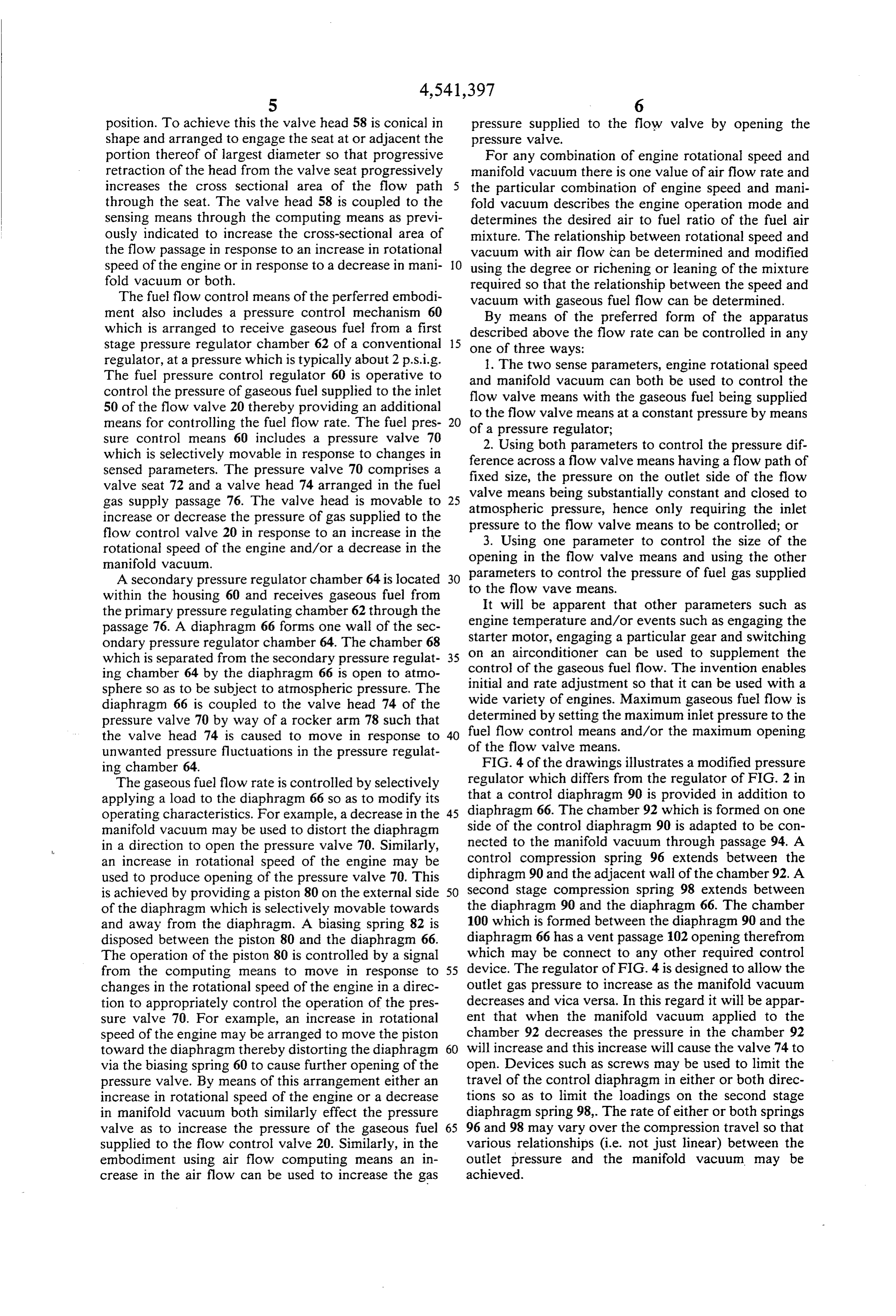
sure control means 60 includes a pressure valve 70 2. Using both parameters to control the pressure dif which is selectively movable in response to changes in ference across a flow valve means having a flow path of sensed parameters. The pressure valve 70 comprises a fixed size, the pressure on the outlet side of the flow valve seat 72 and a valve head 74 arranged in the fuel gas supply passage 76. The valve head is movable to 25 valve means being substantially constant and closed to increase or decrease the pressure of gas supplied to the atmospheric pressure to pressure, hence only requiring the inlet the flow valve means to be controlled; or flow control valve 20 in response to an increase in the 3. Using one parameter to control the size of the rotational speed of the engine and/or a decrease in the opening in the flow valve means and using the other manifold vacuum.
A secondary pressure regulator chamber 64 is located 30 to parameters to control the pressure of fuel gas supplied the flow wave means.
within the housing 60 and receives gaseous fuel from It will be apparent that other parameters such as the primary pressure regulating chamber 62 through the engine temperature and/or events such as engaging the passage 76. A diaphragm 66 forms one wall of the sec starter motor, engaging a particular gear and switching ondary pressure regulator chamber 64. The chamber 68 which is separated from the secondary pressure regulat 35 on an airconditioner can be used to supplement the ing chamber 64 by the diaphragm 66 is open to atmo control of the gaseous fuel flow. The invention enables sphere so as to be subject to atmospheric pressure. The initial and rate adjustment so that it can be used with a diaphragm 66 is coupled to the valve head 74 of the wide variety of engines. Maximum gaseous fuel flow is pressure valve 70 by way of a rocker arm 78 such that determined by setting the maximum inlet pressure to the the valve head 74 is caused to move in response to 40 of fuel flow control means and/or the maximum opening unwanted pressure fluctuations in the pressure regulat the flow valve means.
ing chamber 64. FIG. 4 of the drawings illustrates a modified pressure The gaseous fuel flow rate is controlled by selectively regulator which differs from the regulator of FIG. 2 in applying a load to the diaphragm 66 so as to modify its that a control diaphragm 90 is provided in addition to operating characteristics. For example, a decrease in the diaphragm 66. The chamber 92 which is formed on one manifold vacuum may be used to distort the diaphragm side of the control diaphragm 90 is adapted to be con in a direction to open the pressure valve 70. Similarly, nected to the manifold vacuum through passage 94. A an increase in rotational speed of the engine may be control compression spring 96 extends between the used to produce opening of the pressure valve 70. This diphragm 90 and the adjacent wall of the chamber 92. A is achieved by providing a piston 80 on the external side 50 second stage compression spring 98 extends between of the diaphragm which is selectively movable towards the diaphragm 90 and the diaphragm 66. The chamber and away from the diaphragm. A biasing spring 82 is 100 which is formed between the diaphragm 90 and the disposed between the piston 80 and the diaphragm 66. diaphragm 66 has a vent passage 102 opening therefrom The operation of the piston 80 is controlled by a signal which may be connect to any other required control from the computing means to move in response to 55 device. The regulator of FIG. 4 is designed to allow the changes in the rotational speed of the engine in a direc outlet gas pressure to increase as the manifold vacuum tion to appropriately control the operation of the pres decreases and vica versa. In this regard it will be appar sure valve 70. For example, an increase in rotational ent that when the manifold vacuum applied to the speed of the engine may be arranged to move the piston chamber 92 decreases the pressure in the chamber 92 toward the diaphragm thereby distorting the diaphragm 60 will increase and this increase will cause the valve 74 to via the biasing spring 60 to cause further opening of the open. Devices such as screws may be used to limit the pressure valve. By means of this arrangement either an travel of the control diaphragm in either or both direc increase in rotational speed of the engine or a decrease tions so as to limit the loadings on the second stage in manifold vacuum both similarly effect the pressure diaphragm spring 98,. The rate of either or both springs valve as to increase the pressure of the gaseous fuel 65 96 and 98 may vary over the compression travel so that supplied to the flow control valve 20. Similarly, in the various relationships (i.e. not just linear) between the embodiment using air flow computing means an in outlet pressure and the manifold vacuum may be crease in the air flow can be used to increase the gas achieved.
Page 8
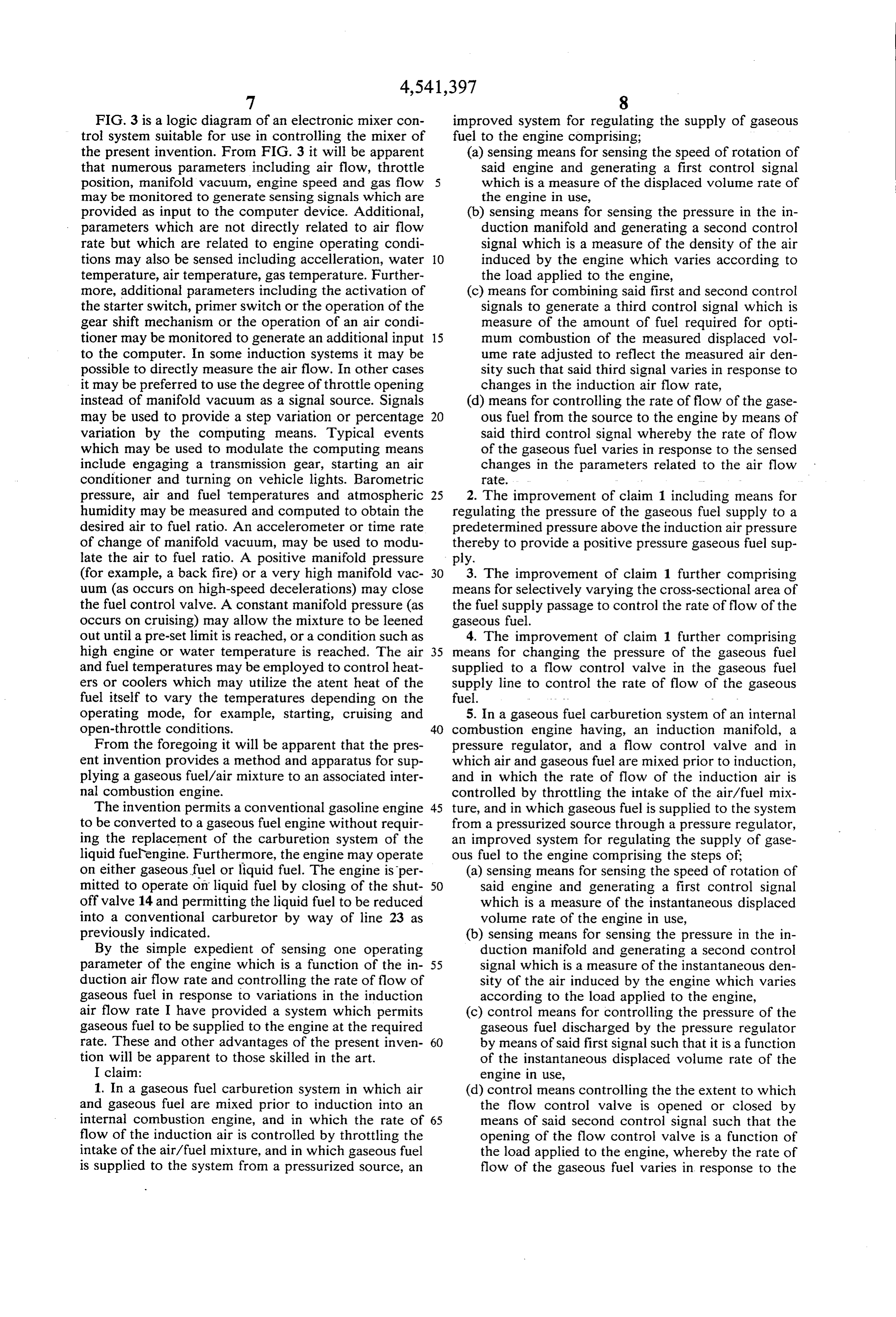
FIG. 3 is a logic diagram of an electronic mixer con improved system for regulating the supply of gaseous trol system suitable for use in controlling the mixer of fuel to the engine comprising; the present invention. From FIG. 3 it will be apparent (a) sensing means for sensing the speed of rotation of that numerous parameters including air flow, throttle said engine and generating a first control signal position, manifold vacuum, engine speed and gas flow 5 which is a measure of the displaced volume rate of may be monitored to generate sensing signals which are the engine in use, provided as input to the computer device. Additional, (b) sensing means for sensing the pressure in the in parameters which are not directly related to air flow duction manifold and generating a second control rate but which are related to engine operating condi signal which is a measure of the density of the air tions may also be sensed including acceleration, water 10 induced by the engine which varies according to temperature, air temperature, gas temperature. Further the load applied to the engine, more, additional parameters including the activation of (c) means for combining said first and second control the starter switch, primer switch or the operation of the signals to generate a third control signal which is gear shift mechanism or the operation of an air condi measure of the amount of fuel required for opti tioner may be monitored to generate an additional input 15 mum combustion of the measured displaced vol to the computer. In some induction systems it may be ume rate adjusted to reflect the measured air den possible to directly measure the air flow. In other cases sity such that said third signal varies in response to it may be preferred to use the degree of throttle opening changes in the induction air flow rate, instead of manifold vacuum as a signal source. Signals (d) means for controlling the rate of flow of the gase may be used to provide a step variation or percentage 20 ous fuel from the source to the engine by means of variation by the computing means. Typical events said third control signal whereby the rate of flow which may be used to modulate the computing means of the gaseous fuel varies in response to the sensed include engaging a transmission gear, starting an air changes in the parameters related to the air flow conditioner and turning on vehicle lights. Barometric rate.
pressure, air and fuel temperatures and atmospheric 25 2. The improvement of claim 1 including means for humidity may be measured and computed to obtain the regulating the pressure of the gaseous fuel supply to a desired air to fuel ratio. An accelerometer or time rate predetermined pressure above the induction air pressure of change of manifold vacuum, may be used to modu thereby to provide a positive pressure gaseous fuel sup late the air to fuel ratio. A positive manifold pressure ply.
(for example, a back fire) or a very high manifold vac 3. The improvement of claim 1 further comprising uum (as occurs on high-speed decelerations) may close means for selectively varying the cross-sectional area of the fuel control valve. A constant manifold pressure (as the fuel supply passage to control the rate of flow of the occurs on cruising) may allow the mixture to be leened gaseous fuel.
out until a pre-set limit is reached, or a condition such as 4. The improvement of claim 1 further comprising high engine or water temperature is reached. The air 35 means for changing the pressure of the gaseous fuel and fuel temperatures may be employed to control heat supplied to a flow control valve in the gaseous fuel ers or coolers which may utilize the atent heat of the supply line to control the rate of flow of the gaseous fuel itself to vary the temperatures depending on the fuel.
Operating mode, for example, starting, cruising and 5. In a gaseous fuel carburetion system of an internal open-throttle conditions. 40 combustion engine having, an induction manifold, a From the foregoing it will be apparent that the pres pressure regulator, and a flow control valve and in ent invention provides a method and apparatus for sup which air and gaseous fuel are mixed prior to induction, plying a gaseous fuel/air mixture to an associated inter and in which the rate of flow of the induction air is nal combustion engine. controlled by throttling the intake of the air/fuel mix The invention permits a conventional gasoline engine 45 ture, and in which gaseous fuel is supplied to the system to be converted to a gaseous fuel engine without requir from a pressurized source through a pressure regulator, ing the replacement of the carburetion system of the an improved system for regulating the supply of gase liquid fuelengine. Furthermore, the engine may operate ous fuel to the engine comprising the steps of on either gaseous fuel or liquid fuel. The engine is per (a) sensing means for sensing the speed of rotation of mitted to operate on liquid fuel by closing of the shut 50 said engine and generating a first control signal off valve 14 and permitting the liquid fuel to be reduced which is a measure of the instantaneous displaced into a conventional carburetor by way of line 23 as volume rate of the engine in use, previously indicated. (b) sensing means for sensing the pressure in the in By the simple expedient of sensing one operating duction manifold and generating a second control parameter of the engine which is a function of the in- 55 signal which is a measure of the instantaneous den duction air flow rate and controlling the rate of flow of sity of the air induced by the engine which varies gaseous fuel in response to variations in the induction according to the load applied to the engine, air flow rate I have provided a system which permits (c) control means for controlling the pressure of the gaseous fuel to be supplied to the engine at the required gaseous fuel discharged by the pressure regulator rate. These and other advantages of the present inven- 60 by means of said first signal such that it is a function tion will be apparent to those skilled in the art. of the instantaneous displaced volume rate of the I claim: engine in use, 1. In a gaseous fuel carburetion system in which air (d) control means controlling the the extent to which and gaseous fuel are mixed prior to induction into an the flow control valve is opened or closed by internal combustion engine, and in which the rate of 65 means of said second control signal such that the flow of the induction air is controlled by throttling the opening of the flow control valve is a function of intake of the air/fuel mixture, and in which gaseous fuel the load applied to the engine, whereby the rate of is supplied to the system from a pressurized source, an flow of the gaseous fuel varies in response to the
Page 9
variations in the instantaneous displaced volume signal which is a measure of the instantaneous den rate of the engine in use according to the load sity of the air induced by the engine which varies applied to the engine. according to the load applied to the engine, 6. In a gaseous fuel carburetion system of an internal (c) control means controlling the pressure of the gase combustion engine having, an induction manifold, a 5 ous fuel discharged by the pressure regulator by pressure regulator, and a flow control valve and in means of said second control signal such that the which air and gaseous fuel are mixed prior to induction, pressure of the gaseous fuel supplied it is a function and in which the rate of flow of the induction air is controlled by throttling the intake of the air/fuel mix of the instantaneous displaced volume rate of the ture, and in which gaseous fuel is supplied to the system 10 engine in use, from a pressurized source through a pressure regulator, (d) control means controlling the the extent to which an improved system for regulating the supply of gase the flow control valve is opened or closed by ous fuel to the engine comprising the steps of: means of said first signal such that it is a function of (a) sensing means for sensing the speed of rotation of the instantaneous displaced volume rate of the said engine and generating a first control signal 15 engine in use, whereby the rate of flow of the gase which is a measure of the instantaneous displaced ous fuel varies in response to the variations in the volume rate of the engine in use, instantaneous displaced volume rate of the engine (b) sensing means for sensing the pressure in the in in use according to the load applied to the engine. duction manifold and generating a second control k k se s
Provenance
- Collection
- Cited prior art
- Original PDF
- patentimages.storage.googleapis.com →
- Filed
- 1984-04-30
- Pages
- 9
- Method
- pdftotext (the PDF's own text layer) + pdftoppm 300dpi page scans
- Source
- Google Patents bibliographic record
- Granted
- 1985-09-17
- Inventors
- Colin G. Young; Emco Wheaton International Ltd
- Transcribed from
- patentimages.storage.googleapis.com →