patent · US5690483
Gaseous fuel burner
25 November 1997
Page 1 — bibliographic record
United States Patent (19) 11 Patent Number: 5,690483 Oda et al. 45) Date of Patent: Nov. 25, 1997 54 GASEOUS FUEL BURNER 3,289,731 12/1966 Geber .................................. 43,354 X 3,825,404 7/1974 DeGouville ... 431/354 75 Inventors: Kenneth J. Oda, Elk Grove Village; 4217,880 8/1980 Turner, Jr. .. ... 126,531 Donald M. Krueger, Westchester;
S.S.S. Serge 5,149.262 9/1992 Riehl .......... 26/39 K. s s 5.492.469 2/1996 Oda et al. .. ... 431/266
Bloomingdale, all of Ill. 5,545,036 8/1996 Kwiatek ..... ... 431/266 5,620,317 4/1997 Sigler ...................................... 43/266 73) Assignee: Eaton Coporation, Cleveland, Ohio igler 21 Appl. No.: 682,464 Primary Examiner-Larry Jones 22 Filed
Jul.d 17, 1996 Attorney, Agent, or Firm-Roger A. Johnston 6 y 57 ABSTRACT 51 Int. Cl. ............................................... F23Q 3100 52 U.S. Cl. ....................... 431/266; 431/354; 126/39 R: A gaseous fuel burner with a base formed of cast aluminum 126/39 E and a wafer cooperating with the base for forming an annular 58 Field of Search ................................ 126/39 R, 39 E, of flame generating ports. A cap is received over the wafer 126/39 D, 39 H, 39 K; 431/354, 266,328, and forms a dead air space for reducing the temperature rise 326 of the cap. The wafer and base are formed of aluminum or brass and the cap is either formed of cast iron or cast 56) References Cited aluminum with a porcelainized steel disc insert on the upper Surface,
1,506,168 8/1924. Erikstrup ............................ 431/354 X 14 Claims, 4 Drawing Sheets
Page 2
Drawing sheet — no readable text.
Page 3
Drawing sheet — no readable text.
Page 4
Drawing sheet — no readable text.
Page 5
Drawing sheet — no readable text.
Page 6
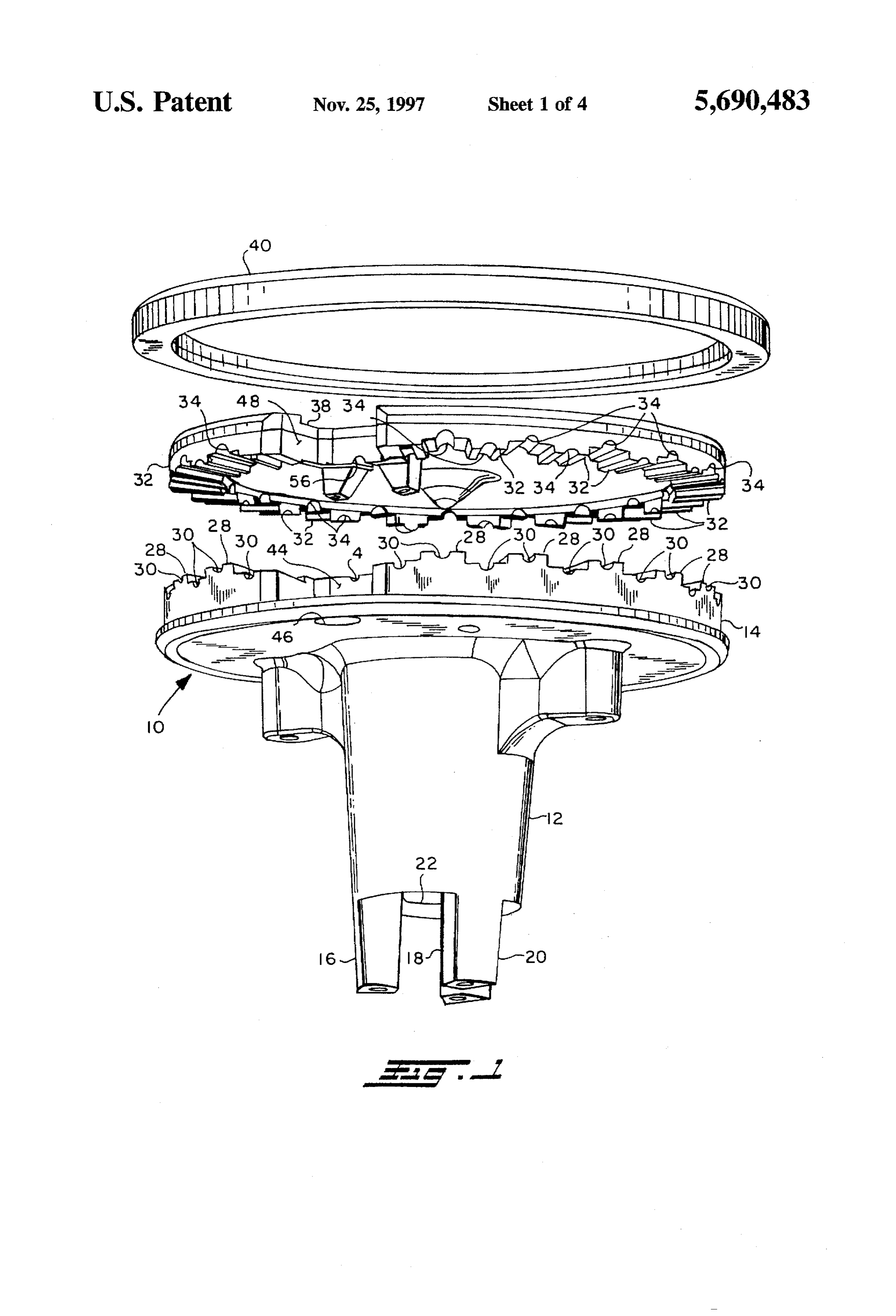
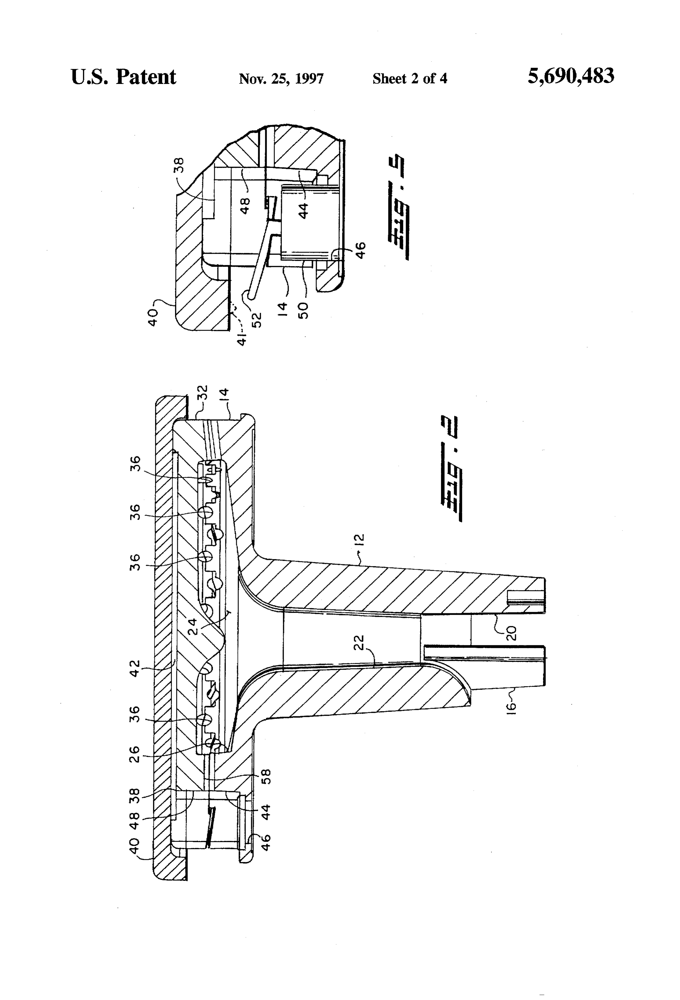
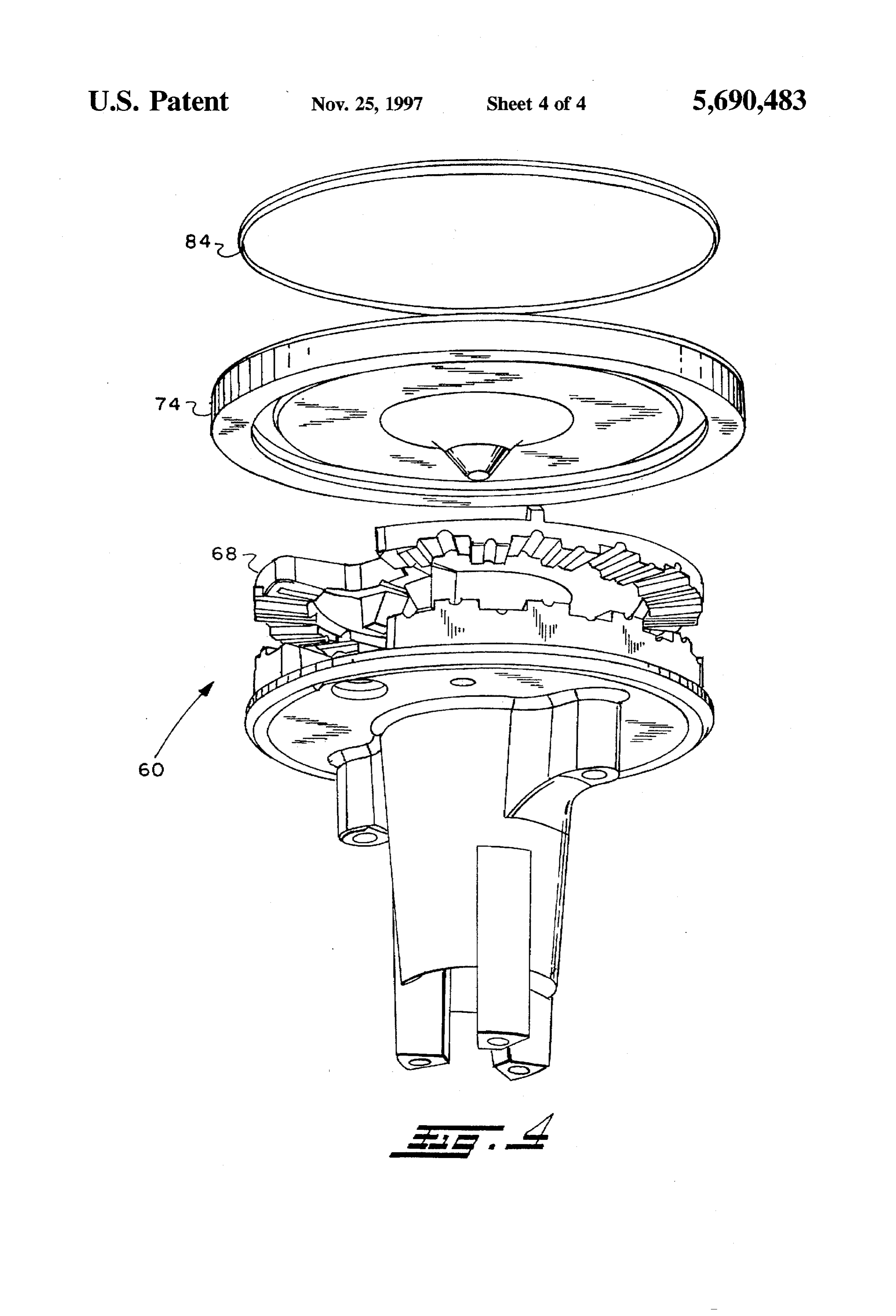
GASEOUS FUEL BURNER FIG. 4 is an exploded view of the burner of FIG. 3; and, FIG. 5 is an enlarged detail of a portion of FIG. 2.
BACKGROUND OF THE INVENTION DETALED DESCRIPTION
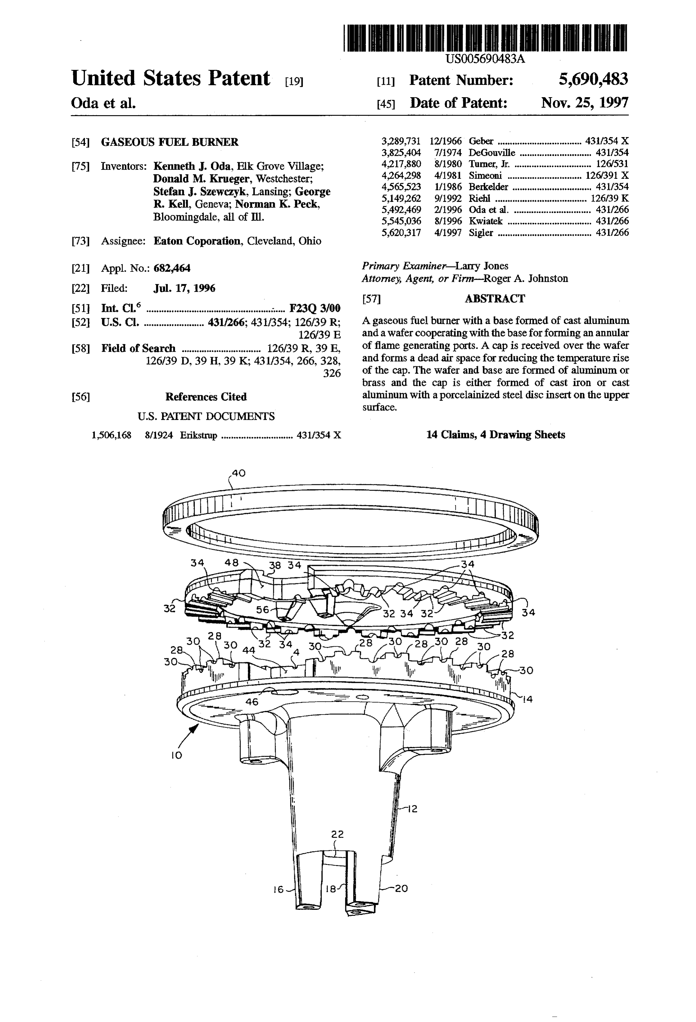
The present invention relates to burners for gaseous Referring to FIGS. 1 and 2, one embodiment burner fuel/air mixtures such as are employed for cooking appli assembly practicing the present invention is illustrated gen ances and particularly cook tops and range tops utilized for erally at 10 and includes a base having a generally cylin household and commercial cooking. Gaseous fuel burners drical attachment portion 12 and an enlarged diameter flame for top cooking are typically arranged in an annular con generating port forming portion 14 with a plurality of figuration with a plurality of flame generating ports disposed 10 integrally formed attachment stanchions 16, 1820, which to provide a virtual ring of flame for heating a receptacle stanchions define therebetween air inlet passages to the such as in a pot, a pan or a boiler containing liquid or central fuel/air inlet passage 22 The inlet passage 22 com comestibles. Currently, mass produced burners for cooktop municates with a plenum cavity. 24 which is bounded by an usage have the burner assembly arranged to be received over 15 annular wall 26 formed on an enlarged portion 14 of the base a fuel Supply tube in such a manner that the interconnection with the upper axial face of the wall 26 having formed of the tube to the burner forms an aspirator for drawing in thereon a plurality of castellations 28 each of which has primary combustion air which is mixed in a plenum chamber formed thereon a groove 30.
within the burner and discharged through the flame gener A wafer 32 having a generally circular or disc-like con ating ports. Such annular fuel burner arrangements for top 20 figuration burners of cooking appliances are commonly ignited by a formed on has a corresponding plurality of castellations 32 spark discharge electrode provided adjacent the flame gen a plurality of grooves 34thereof the undersurface about the periphery with erating ports; and, electrical circuitry is employed for user disposed to cover cavity 24 with thetherein.
castellations thereof operated initiation of the spark discharge upon commence interdigitated with the grooves castellations 30 of the portion ment of burner usage. 25 14 of the base to define a plurality of flame generating ports Heretofore, annular cooktop burners have either been denoted by reference numeral 36 in FIG. 2. The upper face stamped or cast of iron based material such as stainless steel of wafer 32 has a recess or cavity 38 formed therein which or cast iron to form the burner ring in order to utilize is covered by a cap 40 having the rim formed to extend materials able to withstand the temperatures of the flame. outwardly from the outer periphery 32 of the wafer. The However, the use of iron based materials for the burner base 30 recess 38 thus forms with the cap a closed chamber in the and portion forming the flame generating ports has proven to form of a dead airspace 42 formed between the recess 38 in be costly in terms of material costs, tooling and manufac the upper surface of the wafer and the undersurface of the turing operations for high-volume mass production of cap 40.
domestic cooktop appliances. It has thus been desired to find a way of making an annular or ring shaped cooktop burner 35 44The enlarged ring portion 14 of the base 12 has a pocket from light material and with reduced cost manufacturing adjacentportsin30theandperiphery formed thereof between two of the a hole or aperture 46 is formed through techniques. the base for receiving therein a suitable spark ignitor. A It has been attempted to form a gaseous fuel burner from corresponding pocket 48 is formed in the wafer 32. light metal such as aluminum to enable the burner to be Referring to FIG. 5, the aperture 46 in the base has fabricated by low cost techniques such as casting; however, received the flame temperature has resulted in melting of the burner which hastherein a holder 50 formed of insulating material cap where the cap has been formed of as cast aluminum. a spark discharge to therefrom extending an electrode 52 for providing the undersurface of the rim of cap 40.
Although it has been found that an aluminum burner cap will withstand the flame temperatures if the cap is alloyed with 54,Referring 56 formed to FIG. 1, the ignitor pocket 44, 48 has grooves respectively therein in the backwall thereof iron or forged, such techniques of construction have been 45 which form a flame generating port 58 (see FIG. 2) in the found to be prohibitively costly for mass production of assembled burner through which fuel/air mixture passes to cooktop burners for household appliances. be ignited by the spark discharged from electrode 52. SUMMARY OF THE INVENTION The portion of the recess 38 in the upper surface of the 50 wafer 32 in the region of the pocket 48 provides an area into
The present invention provides an annular gaseous fuel burner suitable for cooktop applications which has a cast which the flame generated at the ignitor port 58 can enter; and, this area of the recess serves as a flame stabilization aluminum base and flame generating ring formed of either region.
cast aluminum or brass with a flame deflecting cover or cap The undersurface of cap 40 is preferably roughened in the formed of either cast iron or aluminum having a ceramic 55 region of pocket 44 to direct arcing from the igniter elec coated steel insert. The burner has an air plenum formed trode. Alternatively between the flame generating wafer and the cover to pro as shown in dashed aoutline slight projection extending downward vide thermal isolation of the cover to prevent melting of the 41 may be provided on the in FIG. 5 by reference numeral cap.
as cast aluminum material.
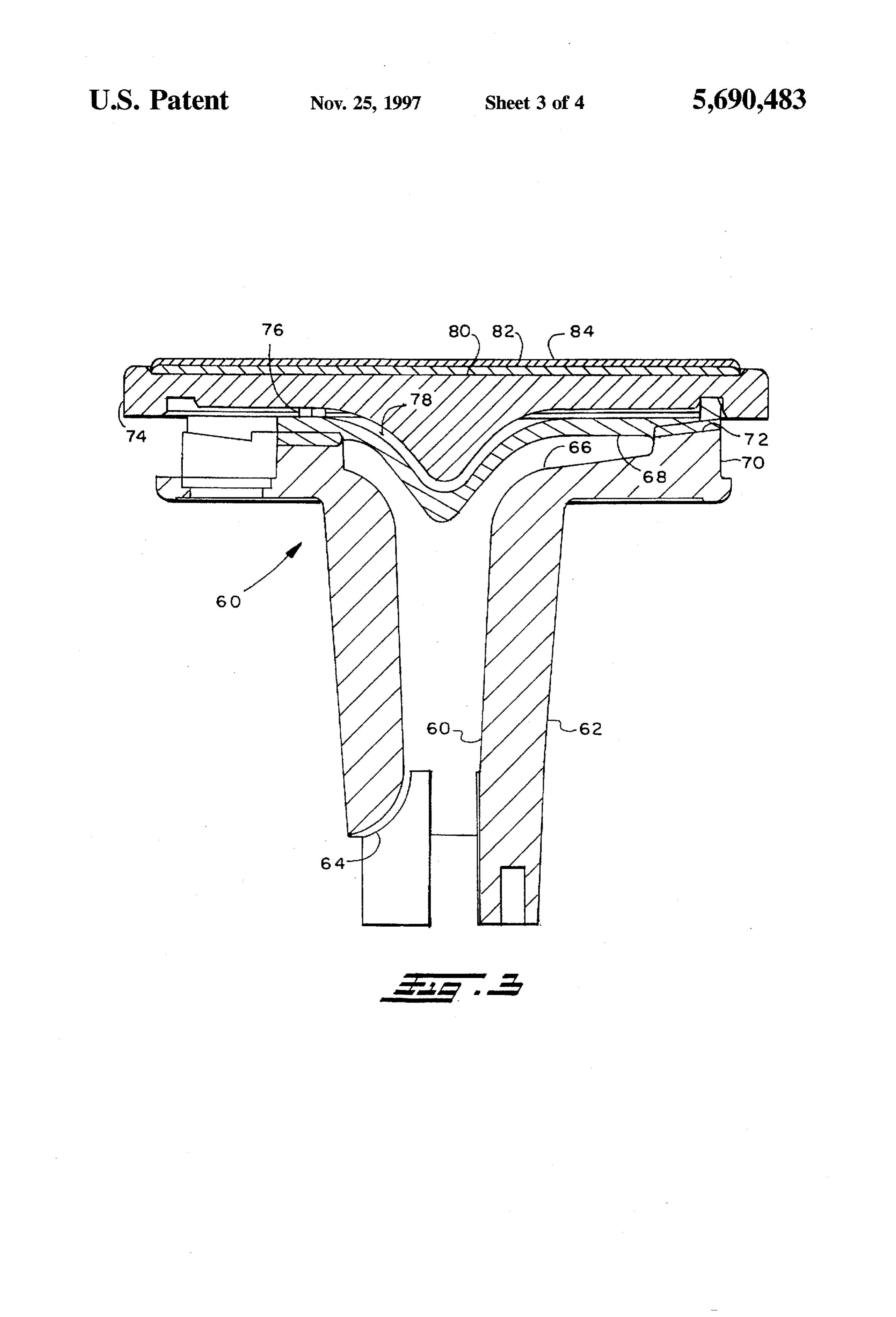
Referring to FIGS. 3 and 4, another embodiment of the
BRIEF DESCRIPTION OF THE DRAWINGS invention indicated generally at 60 and has a body having a reduced diameter portion 62 having an inlet passage 64
FIG. 1 is an exploded view of a cast aluminum burner formed therein with aspirating slots such as the one identi having a cast iron cap; fied by reference numeral 64 for providing aflow of gaseous FIG. 2 is a cross-sectional view of the assembled burner fuel and air in passage 60 upward to an enlarged plenum of FIG. 1; 65 cavity 66. The upper end of the burner base has an enlarged FIG. 3 is a cross-sectional view of a burner having a cast diameter portion 70 with a plenum cavity 66 formed therein aluminum base and cap with a brass wafer; which is closed by a generally circular wafer 68 received
Page 7
thereover. In the present practice of the invention of the 3. The burner assembly defined in claim 1, wherein said embodiment of FIG. 3, the wafer 68 is formed of cast brass cap extends radially outwardly of said wafer. material and cooperates with the rim of enlarged diameter 4. The burner assembly defined in claim 1, wherein said portion 70 of the base to form a plurality of circumferentially wafer is formed Substantially of aluminum and said cap is spaced castellated surfaces which are interdigitated and form 5 formed substantially of iron material. a plurality of flame generating ports 72 in a manner similar 5. The burner assembly defined in claim 1, wherein said to the embodiment of FIG. 2. base, water and cap are formed substantially of aluminum An aluminum cap 74 is received over the wafer 68 and material.
registered thereagainst on a plurality of circumferentially 6. The burner assembly defined in claim 1, wherein said spaced stanchions disposed on the upper surface of the wafer O cap is formed of aluminum and includes a steel disc having 68, one of which is illustrated in FIG. 3 and denoted by a refractory coating.
reference numeral 76. The undersurface of the cap is 7. The burner assembly defined in claim 1, wherein said recessed to define a dead air space 78 between the upper cap includes a member having a porcelain coating. surface of the wafer 68 and the under surface of cap 74 5 8. The burner assembly defined in claim 1, wherein said Referring to FIGS. 3 and 4, the upper surface of cap 74 base is formed substantially of aluminum material. 9. The burner assembly defined in claim 1, wherein said has a recess 80 formed therein into which is received a disc 82 which is formed substantially of iron material and which base is formed of substantially aluminum, said wafer is formed substantially of copper alloy material and said cap has a refractory or ceramic coating 84 on the exposed includes a relatively thin disc formed of steel and said surface thereof for protecting the upper surface of the aluminum cap 74. In the presently preferred practice, cap 74 coating comprises porcelain material. 10. The burner assembly defined in claim 1, wherein said has the upper surface thereof porcelainized. cap defines an ignition pocket intermediate two of said The present invention thus provides a unique and novel plurality ring burner assembly formed of light metal and having the cap defineofaflame recess generating ports and said wafer and said therebetween said recess communicating cap thereof provided with a temperature reducing dead air 25 with said pocket for enhancing fuel-air ignition in said space on the undersurface thereof for preventing melting of pocket.
the light metal from the heat of the burner flame or 11. A burner assembly for gaseous fuel comprising: alternatively, the cap is formed of iron material. (a) a body formed of metallic material having a melting Although the present invention has hereinabove been pointless than the ignition temperature of said fuel and described with respect to the illustrated embodiments, it will having an annular configuration with an inlet adapted be understood that the invention is capable of modification for connections to a source of gaseous fuel and air and and variation and is limited only by the scope of the communicating with a cavity defined by a portion distal following claims. said inlet;
We claim:
1. A burner assembly for gaseous fuel comprising: 35 (b) a wafer disposed over said cavity and closing same to form a fuel air-plenum chamber and cooperating with (a) a body formed of a metallic material having a melting said base to define a plurality of peripheral flame pointless than the ignition temperature of said fuel and generating ports each communicating with said fuel-air having an annular configuration with an inlet adapted plenum chamber and an ignition pocket, said pocket for connection to a source of gaseous fuel and air and adapted for having a spark ignitor disposed therein; communicating with a cavity defined by a portion distal (c) a cap formed of metallic material and disposed over said inlet; said wafer and closing said pocket, said cap having the (b) a wafer disposed over said cavity and closing same to surface thereof closing said pocket being a rough form a fuel-air plenum chamber and cooperating with surface for directing arcing of said spark ignitor. said base to define a plurality of peripheral flame 12. The burner defined in claim 11, wherein said cap and generating ports each communicating with said fuel-air 45 water define therebetween an air plenum for limiting the plenum chamber; and, temperature rise of cap.
(c) a cap formed substantially of metallic material and 13. The burner defined in claim 11, wherein said cap is disposed over said wafer, said cap and wafer defining formed of material selected from the group consisting essen therebetween an air plenum for limiting the tempera 50 tially of aluminum, copper alloy and iron. ture rise of said cap. 14. The burner defined in claim 11, wherein said rough 2. The burner assembly defined in claim 1 wherein said surface of said cap includes a projection extending there wafer is formed of material selected from the group con from into said pocket.
sisting essentially of aluminum and copper alloy and said cap is formed of substantially iron material. st : it it
Provenance
- Collection
- Cited prior art
- Original PDF
- patentimages.storage.googleapis.com →
- Filed
- 1996-07-17
- Pages
- 7
- Method
- pdftotext (the PDF's own text layer) + pdftoppm 300dpi page scans
- Source
- Google Patents bibliographic record
- Granted
- 1997-11-25
- Inventors
- Kenneth J. Oda; Donald M. Krueger; Stefan J. Szewczyk; George R. Kell; Norman K. Peck; Eaton Corp
- Transcribed from
- patentimages.storage.googleapis.com →