patent · US4505260
Radiant energy device
19 March 1985
Page 1 — bibliographic record
: - . . . . . w W.
3. A 9 f 85 XF 4 5 OS 26
United States Patent (19) 11 Patent Number: 4,505,260 Metzger 45) Date of Patent: Mar. 19, 1985 54 RADIANT ENERGY DEVICE 7945 l/1981 Japan ................................... 126/440 (75) Inventor: James B. Metzger, Princeton, N.J. 23666 3/1981 Japan. ... 126/424 190901 11/1982 Japan ................................... 350/418 (73) Assignee: Metzger Research Corporation, Primary Examiner-Margaret A. Focarino Princeton, N.J.
21 Appl. No.: 406,253 57 ABSTRACT 22 Filed: Sep. 9, 1982 Radiant energy such as solar energy is utilized to form a vapor from a liquid state of a material. Concentrated (51) Int. Cl. ................................................. F24J 3/02 radiant energy is directed through a liquid lens to a (52) U.S. Cl. .................................... 126/433; 126/426; target for absorption of the radiation. The target in this 126/439; 126/440; 126/443; 350/418 way is heated to a high temperature and produces steam 58 Field of Search ............... 126/433,438,439, 440, or other vapor at high pressure. High efficiency at low 126/441, 443, 900, 426; 350/418 over-all cost is achieved by (1) the direct vaporization (56) References Cited of a liquid within a collector enclosing the target struc ture; (2) the recovery of energy absorbed by the liquid
1,081,098 12/1913 De La Garza ................. 126/440 X heat losses in the solar collector by special enclosure of 3,125,091 3/1964 Sleeper ........................... 126/440X the target within the collector; (4) recovery of heat as 4,249,516 2/1981 Stark ................................... 126/439 blackbody radiation from the target by using reflective 4,289,119 9/1981 Meyer ................................. 126/440 walls within the enclosure and/or permitting absorption 4,341,204 7/1982 Bloxsom .............................. 126/440 of the blackbody radiation by the liquid lens; and (5) an FOREIGN PATENT DOCUMENTS optional use of a heat pump effect for increasing the output of the collector.
2478801 9/1981 France ................................ 26/440 9 Claims, 7 Drawing Figures
Page 2
Drawing sheet — no readable text.
Page 3
Drawing sheet — no readable text.
Page 4
Drawing sheet — no readable text.
Page 5
Drawing sheet — no readable text.
Page 6
been of high cost and relatively poor efficiency. Some
RADANT ENERGY DEVICE systems have used special geometric designs for the
FIELD OF THE INVENTION
mirrors that permit concentration of solar radiation onto a target without tracking the sun directly.
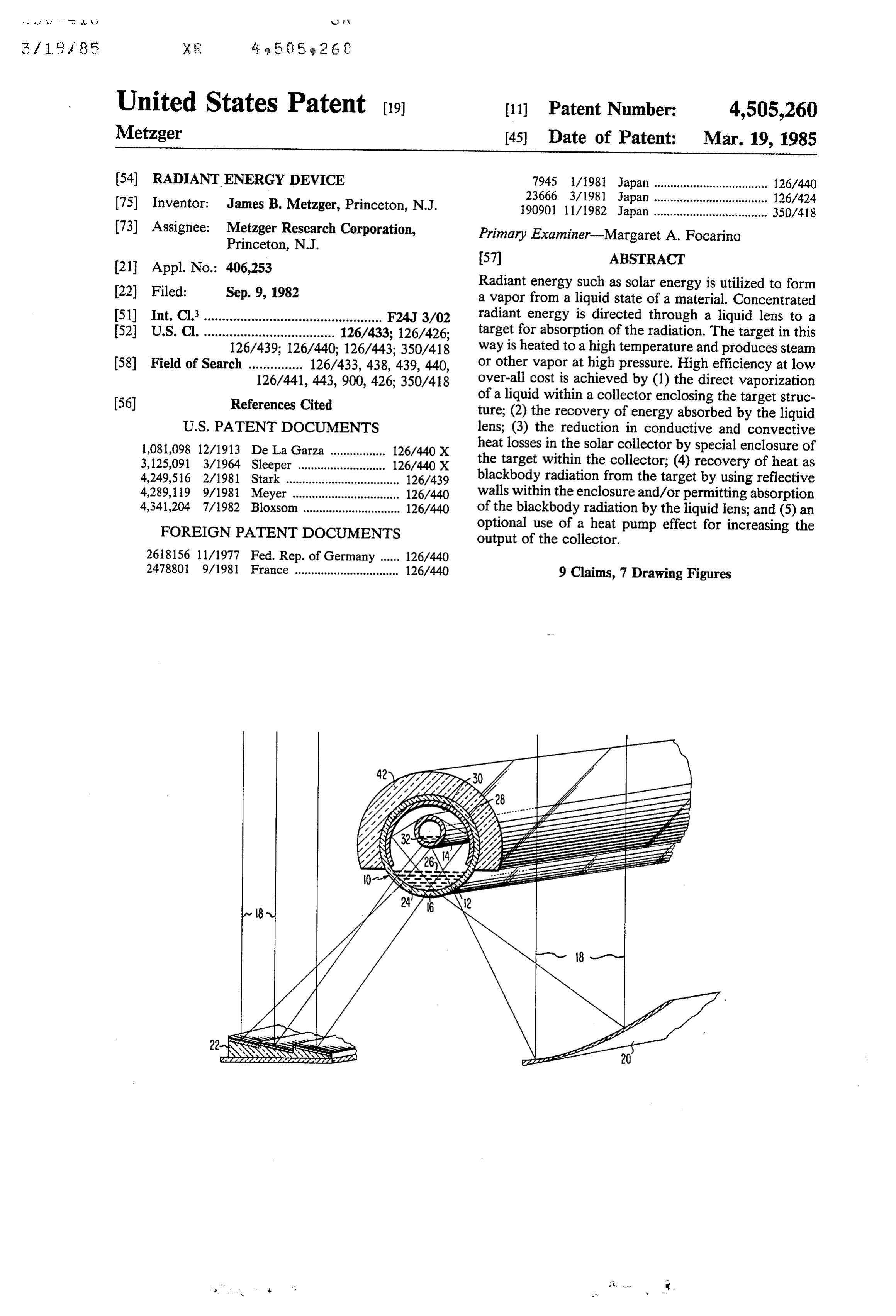
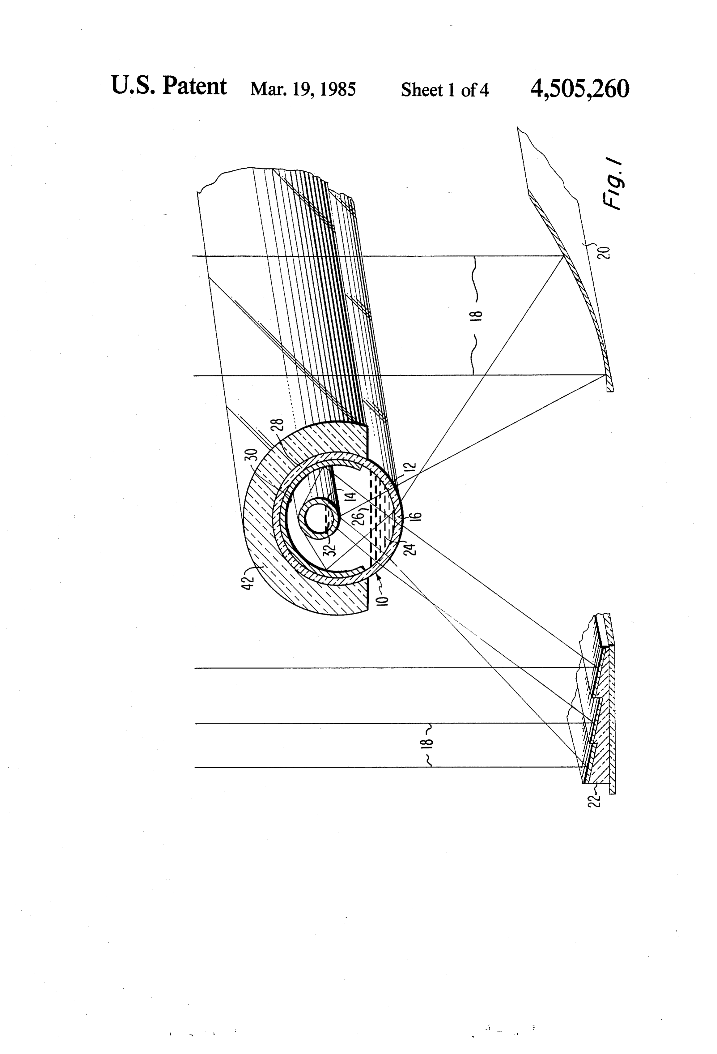
The present invention provides the means for effec BRIEF DESCRIPTION OF THE DRAWINGS tive utilization of radiant energy. Sources of radiant energy include sunlight, nuclear reactors, and the com The following figures show embodiments of the in bustion of fuels. Steam, that is water vapor at or near vention and are not meant to be limiting: 100° C., represents the most commercially versatile FIG. 1 is a transverse sectional view of a radiant form of heat and a highly desirable endproduct pro 10 energy collector device, in accordance with the em duced by embodiments of the present invention. Other bodiments of the invention.
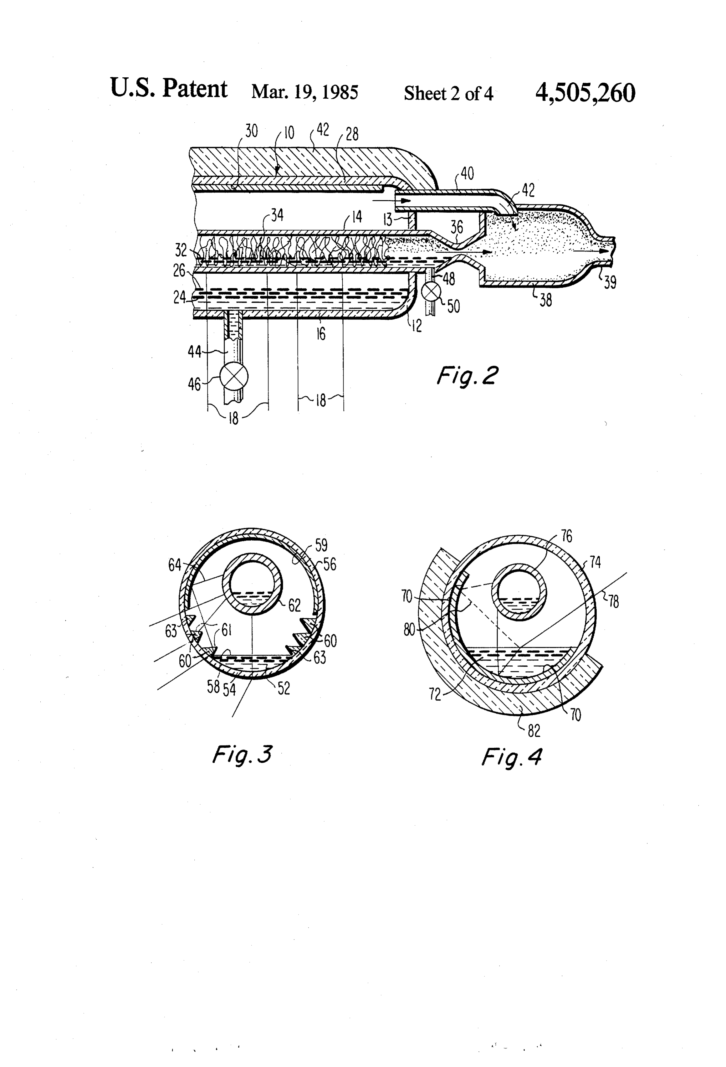
forms of heat may also be produced. For example, the FIG. 2 is a partial longitudinal sectional view of one steam may be used to produce hot water. Other vapors, embodiment of the invention of FIG. 1, wherein addi organic and inorganic, may also be used as the final tional features of the invention are shown. media for transfer of heat, and the invention may be 15 FIG. 3 and FIG. 4 are transverse sectional views of used for supplying heat to drive endothermic chemical further embodiments of the invention.
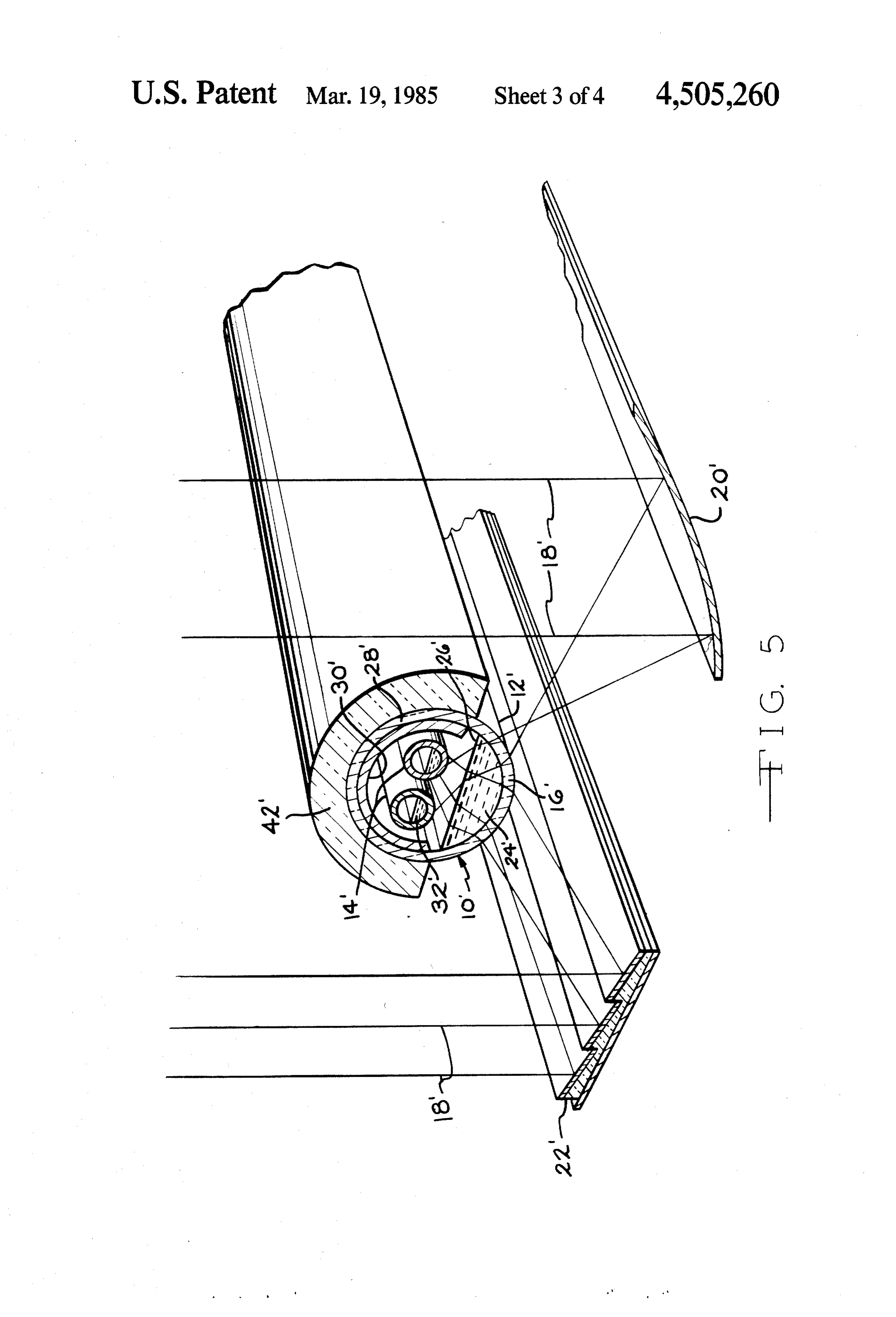
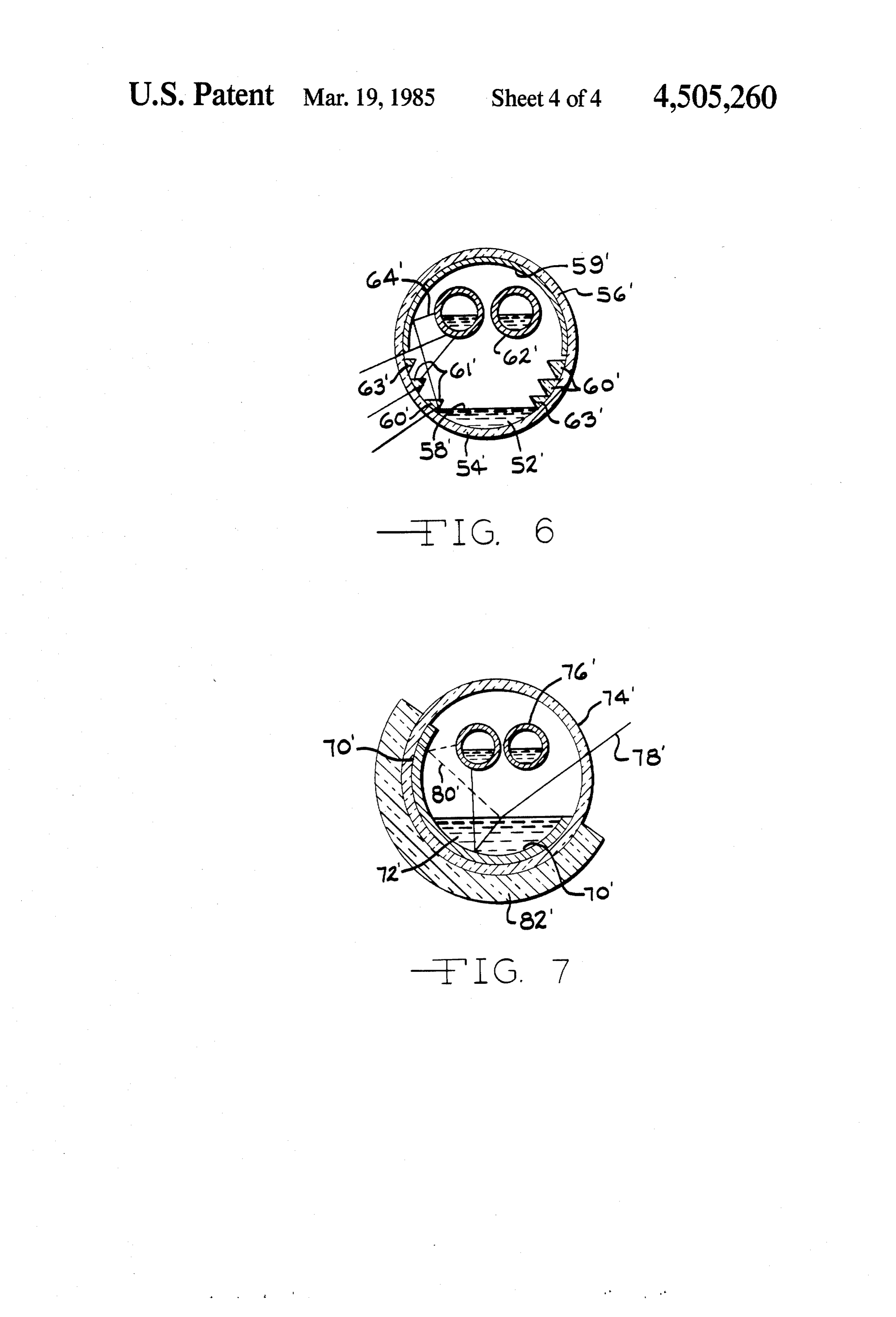
reactions or power engines. FIGS. 5, 6, and 7 are transverse sectional views of Solar energy is an abundant resource that requires embodiments of the invention showing a plurality of inexpensive equipment for its economic utilization. At boiler pipes.
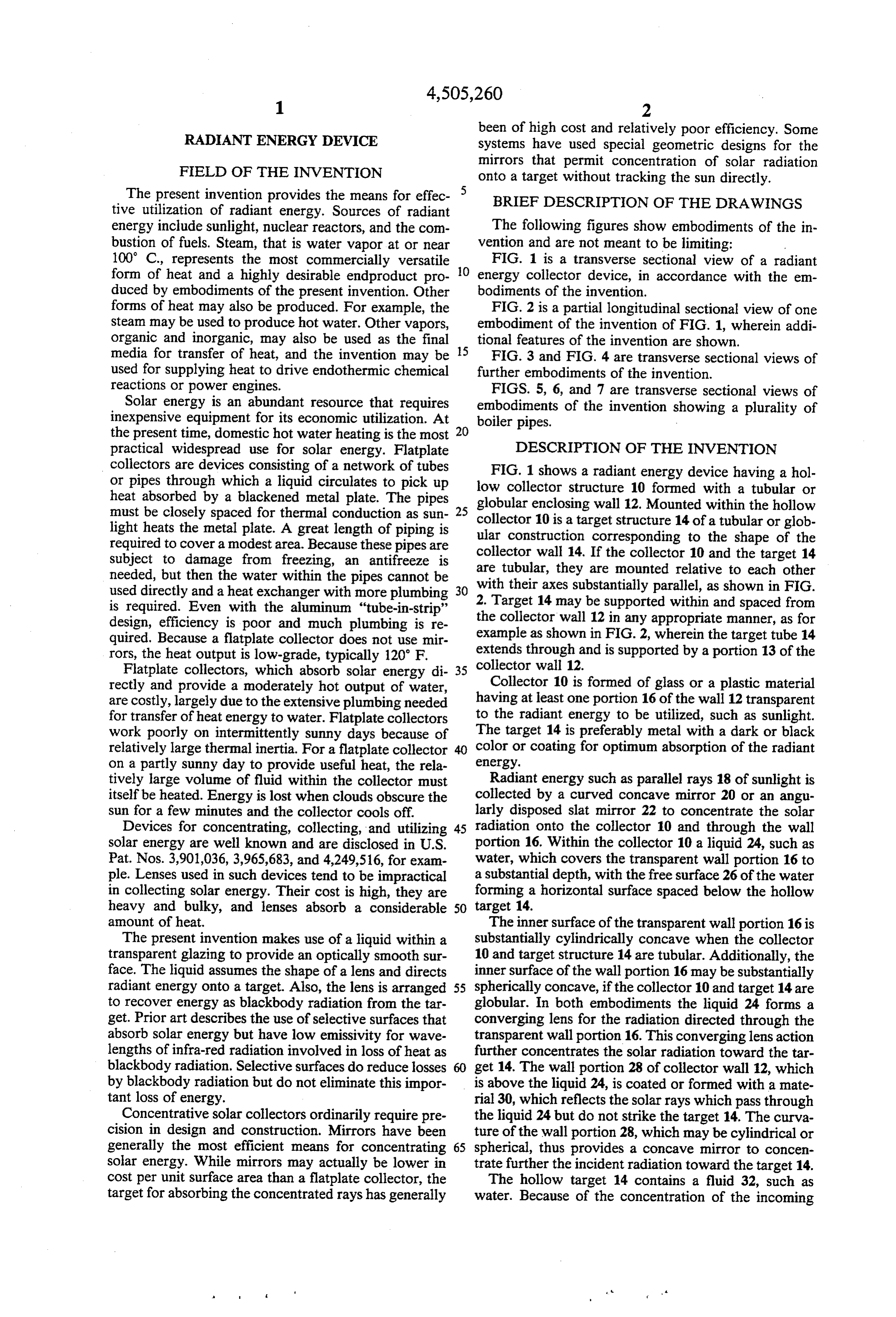
the present time, domestic hot water heating is the most 20 practical widespread use for solar energy. Flatplate DESCRIPTION OF THE INVENTION collectors are devices consisting of a network of tubes or pipes through which a liquid circulates to pick up lowFIG. 1 shows a radiant energy device having a hol collector structure 10 formed with a tubular or heat absorbed by a blackened metal plate. The pipes globular enclosing wall 12. Mounted within the hollow must be closely spaced for thermal conduction as sun 25 collector 10 is a target structure 14 of a tubular or glob light heats the metal plate. A great length of piping is ular construction corresponding to the shape of the required to cover a modest area. Because these pipes are collector wall 14. If the collector 10 and the target 14 subject to damage from freezing, an antifreeze is are tubular, they are mounted relative to each other needed, but then the water within the pipes cannot be used directly and a heat exchanger with more plumbing 30 2.with their axes substantially parallel, as shown in FIG. Target 14 may be supported within and spaced from is required. Even with the aluminum "tube-in-strip' design, efficiency is poor and much plumbing is re the collector wall 12 in any appropriate manner, as for quired. Because a flatplate collector does not use mir example as shown in FIG. 2, wherein the target tube 14 rors, the heat output is low-grade, typically 120 F. extends through and is supported by a portion 13 of the Flatplate collectors, which absorb solar energy di collector wall 12.
rectly and provide a moderately hot output of water, Collector 10 is formed of glass or a plastic material are costly, largely due to the extensive plumbing needed having at least one portion 16 of the wall 12 transparent for transfer of heat energy to water. Flatplate collectors to the radiant energy to be utilized, such as sunlight. work poorly on intermittently sunny days because of The target 14 is preferably metal with a dark or black relatively large thermal inertia. For a flatplate collector 40 color or coating for optimum absorption of the radiant on a partly sunny day to provide useful heat, the rela energy.
tively large volume of fluid within the collector must Radiant energy such as parallel rays 18 of sunlight is itself be heated. Energy is lost when clouds obscure the collected by a curved concave mirror 20 or an angu sun for a few minutes and the collector cools off. larly disposed slat mirror 22 to concentrate the solar Devices for concentrating, collecting, and utilizing 45 radiation onto the collector 10 and through the wall solar energy are well known and are disclosed in U.S. portion 16. Within the collector 10 a liquid 24, such as Pat. Nos. 3,901,036, 3,965,683, and 4,249,516, for exam water, which covers the transparent wall portion 16 to ple. Lenses used in such devices tend to be impractical a substantial depth, with the free surface 26 of the water in collecting solar energy. Their cost is high, they are forming a horizontal surface spaced below the hollow heavy and bulky, and lenses absorb a considerable 50 target 14.
amount of heat. The inner surface of the transparent wall portion 16 is The present invention makes use of a liquid within a substantially cylindrically concave when the collector transparent glazing to provide an optically smooth sur 10 and target structure 14 are tubular. Additionally, the face. The liquid assumes the shape of a lens and directs inner surface of the wall portion 16 may be substantially radiant energy onto a target. Also, the lens is arranged 55 spherically concave, if the collector 10 and target 14 are to recover energy as blackbody radiation from the tar globular. In both embodiments the liquid 24 forms a get. Prior art describes the use of selective surfaces that converging lens for the radiation directed through the absorb solar energy but have low emissivity for wave transparent wall portion 16. This converging lens action lengths of infra-red radiation involved in loss of heat as further concentrates the solar radiation toward the tar blackbody radiation. Selective surfaces do reduce losses get 14. The wall portion 28 of collector wall 12, which by blackbody radiation but do not eliminate this impor is above the liquid 24, is coated or formed with a mate tant loss of energy. rial 30, which reflects the solar rays which pass through Concentrative solar collectors ordinarily require pre the liquid 24 but do not strike the target 14. The curva cision in design and construction. Mirrors have been ture of the wall portion 28, which may be cylindrical or generally the most efficient means for concentrating 65 spherical, thus provides a concave mirror to concen solar energy. While mirrors may actually be lower in trate further the incident radiation toward the target 14. cost per unit surface area than a flatplate collector, the The hollow target 14 contains a fluid 32, such as target for absorbing the concentrated rays has generally water. Because of the concentration of the incoming
Page 7
radiation by the liquid lens 24 and the converging wall alignment are needed to insure that the concentrated surface 30, target 14 can be made relatively small, such rays actually hit the target. The present invention utiliz that the concentrated radiation quickly heats the water ing the liquid lens 24 and the reflective wall surface 30 32 to steam. provides means for using a relatively small target with Any suitable means may be used to facilitate vapori out requiring precision alignment and without large zation of steam in the hollow target 14. For tubular losses of heat.
pipes of moderate size (FIG. 2), it is convenient to in Normally, glazing placed around a target structure clude a porous, relatively heat-resistant material 34 such results in considerable loss of energy due to reflection as cellulose or glass fibers to absorb the liquid phase in and absorption of radiation by the glazing. The present the pipe. Such a material permits direct vaporization of 10 invention provides a unique liquid-filled window 24 that liquid water absorbed in the fibers without any turbu reduces this loss of energy and serves as a lens or prism lent boiling. to concentrate further the incoming rays to the rela High-pressure steam produced within the target tively small target, 14. Water is an effective medium for structure 14 may be passed into a steam-jet device (FIG. transfer of heat energy. Water vapor is even more effi 2) having a venturi 36 to create a vacuum in a chamber 15 cient than liquid water for carrying away heat. The 38. The venturi 36 is connected at one end to the target present invention provides the means for vaporizing 14 and at its other end to the chamber 38, as shown in water within the solar collector 10. This permits smaller FIG. 2. Chamber 38 may also be a structure separate diameter piping to carry an equivalent amount of heat from tubular target 14 and appropriately connected to away from the device for ultimate use. A nonvolatile the venturi exit of targent 14. Chamber 38 is formed 20 antifreeze with an outlet 39. The relative sizes of the pipes and the presentmay be used along with water, according to invention. The water vapor produced will nozzles in FIG. 2 are somewhat misleading. In practice, be substantially pure and can be directly injected into a the venturi 36 would be of much smaller diameter than either the collector 10 or target 14. domestic hot water system without need for heat ex changers. The water
The high pressure steam issuing into chamber 38 tion, especially the wavelengths 25 of lens 24 absorbs infra-red radia through the venturi 36 forms a partial vacuum in the from the target 14, when heated by of blackbody radiation portion of chamber 38 adjacent to the venturi36. A tube ically, the water vapor surrounding solar energy. Specif 40 connects the space within the collector 10 with the the inner surface of the liquid lens 24 both the target 14 and inner space of the chamber 38. An orifice 42 of tube 40 absorb infra is positioned perpendicular to but just outside the flow 30 redTheradiation from the target.
venturi 36 provides a steam jet at high pressure.
of high velocity steam from the venturi 36. This is the The steam exits at high velocity into the chamber 38. region of the partial vacuum.
In accordance with a feature of the invention, the The orifice 42, perpendicular to but just outside the area partial vacuum formed within chamber 38 is used to of flow of high velocity steam, is the site of the forma remove vapor from the hollow collector 10, if the liquid 35 tion of a partial vacuum, as described. In accordance 24 is volatile, such as water. This facilitates evaporation with used a feature of the invention, this partial vacuum is to aid in the vaporization of the volatile liquid in from the inner surface of the lens 24. This evaporation may proceed at a high rate and keep the liquid lens lens 24 at temperatures as low as O C. for water. This relatively cool while recovering heat from the liquid cooling action may be utilized to provide a source of lens produced from absorption of incoming radiation 18 chilled water for refrigeration or air conditioning. and of secondary blackbody radiation from target 14. However, this vacuum system serves even more effec While most of the near infra-red radiation and visible tively to recover low-grade heat from the liquid lens 24. light of sunlight pass through the liquid lens 24 to heat The venturi-generated vacuum actually provides a the target pipe 14, the longer infra-red wavelengths heat pump effect in permitting evaporation at reduced emanating as blackbody radiation from the target 14 are 45 pressure and temperatures of the liquid lens 24. This absorbed at the inner surface of the liquid lens 24. The vapor from lens 24 admixes with the high velocity reflective surface 30 may be formed as an opaque film of steam from target 14 and the over-all pressure at the constricted outlet 39 increases so that the entire amount aluminum, silver, or another reflective material to aid in directing the incoming radiation to the target 14. A of heat within the steam can be used.
layer of insulation 42 is placed over the reflective por 50 The liquid 24 in the collector 10 may be replaced tion 28 of the collector wall 12. This further reduces through an intake conduit 44 (FIG. 2) controlled by a heat loss and helps to avoid condensation of water on valve 46. In a similar way, the fluid 32 in the target 14 the reflecting surface 30. may be replaced through an inlet pipe 48 through a control valve 50. A source of water for the collector
PRINCIPLES OF THE INVENTION 55 and target may be a reservoir of rain water, deionized The invention provides efficient operation utilizing tap water, or recycled condensate to avoid build-up of three basic elements: (1) A target 14 to absorb the radia boiler scale. Water containing no dissolved gases is also tion, (2) A transparent window 16 (in FIG. 1) or glazing desirable, as gases tend to form bubbles in the liquid lens to protect the target 14 from excessive loss of heat, and 24 interfering with the transmission of light. Additives (3) Effective means for the transfer of the energy from 60 may be incorporated in the liquid lens 24, such as salts, the target 14 to its end use. These three basic elements to increase the refractive index of the lens, increase are provided in a way which facilitates inexpensive transmission of infra-red radiation, and/or serve as an construction and efficient operation. antifreeze. Other additives such as glycerol, sugars, or The target 14 for the absorption of radiant energy soluble polymers such as gelatin may be used for similar may be either of a small or a moderate size compared to 65 purposes or to increase the viscosity of the liquid lens 24 the surface area of the mirrors 20-22 which concentrate to reduce convective heat losses. The range of additives the light onto the target. Small targets obtain high tem is large and inexpensive materials may be selected for peratures quickly, but precision in construction and their desired properties.
Page 8
The devices described above and shown in the draw A further embodiment of the invention is in the use of ings provide energy for various purposes. Pressurized liquid lenses of either spherical and/or segmental con steam from the target 14 could be used to power a tur figuration. A cylindrical lens structure is shown in bine or steam engine prior to its being used to provide cross-section in FIG. 3. A cylindrical liquid lens 52 of heat for a domestic hot water supply. The steam may be the type of lens described above for lens 24 is formed condensed to liberate its heat, and the liquid water may from the cylindrically concave bottom wall portion 54 be reused. Instead of providing a vacuum within the of a horizontally disposed tubular member 56 formed of collector 10 to remove the liquid vapor, a fan could be glass or other appropriate plastic material, transparent used to circulate air through the hollow collector 10. to the radiant energy, such as sunlight to which the The air is thereby heated and humidified to provide 10 device is exposed. The free horizontal surface 58 of the space heating. Sea water may be used for the liquid lens liquid lens 52 forms with its bottom surface a converg 24 and the vapor produced from lens 24 could be con ing lens. A reflective coating 59 coats the upper inner densed and recovered as potable water. A highly hy surface of collector 56. Running parallel with the hori droscopic material such as lithium bromide could be zontally disposed member 56 are parallel hollow ribs or used in target 14 to extract water vapor from the night 15 ridges 60, having a triangular cross-section as shown in air of a desert region passed through the hollow target FIG. 3 with flat faces 61 substantially horizontal and 14. The desert sun would be used to recover this water other faces 63 forming sharp angles with the vertical. by distillation. Ribs 60 are transparent or reflective for collecting radi Losses of energy from a solar collector to the envi ation directed onto the collector wall 54 and directing ronment depend on the size, shape, and exposure of the 20 such radiation toward a tubular metal target 62, similar collector to wind, as well as the temperature of the to target 14 described above.
outer surface of the collector. The present invention The ribs 60 are attached longitudinally to the inner keeps the outer wall of the collector 10 relatively cool wall of the transparent collector 54. Such ribs 60 are because of evaporation taking place at the inner surface easily constructed of glass or plastic attached in a water of the liquid 24. When used for providing space heating, 25 tight manner to the transparent collector cylinder 54. for example, air passed through the collector 10 may Alternatively, the ribs 60 may be manufactured as an reach only 20° C. but have close to 100% humidity. integral part of the cylinder by extrusion from a die. Such moisture-laden air carries considerably more heat The ribs 60 are transparent and are coated with a reflec than dry air, but the outer wall of the transparent collec tive surface on the faces 63. For simplicity, the transpar tor will lose relatively little heat because it is kept cool. 30 ent ribs 60 may have the same refractive index as the The basic design of FIG. 1 and 2 may be modified to liquid used to fill the lens 52.
provide a cover of glass or plastic for the inner surface The ribs 60 permit the composite lens 52 to be far of the liquid lens, 24. If the liquid lens is thus completely thinner and require less liquid than a comparable liquid enclosed, heat may be recovered from the liquid of the filled lens alone. At certain angles of incident rays, the lens by circulating it through a separate evaporator. 35 ribs 60 may act as prisms in refracting light and in pro Another feature of the invention is to use high molec ducing total internal reflection as shown in the ray trac ular weight gases such as carbon dioxide or halogenated ing of FIG. 3. Both reflection and refraction may be hydrocarbons to fill the space between the covered used to direct light to the target 62. Designs other than liquid lens 24 and the target pipe 14. Such gases would cylindrical shape of collector 56 may be used: Parabolic be selected for their properties of infra-red absorption 40 troughs, spherical, and planar geometries are among and the fact that heat losses from conduction in a gas designs which can be tailored to the optical require decrease with an increase in the molecuoar weight of ments for such a collector. The meniscus of some liquids the gas. within the ribs 60 forms an important part of the optical Such high molecular-weight gases such as Freon (a system especially when the ribs are constructed close halogenated hydrocarbon) could be used for heat trans 45 together. The glazing for the target may also consist of fer and as liquids to comprise the liquid lens. Gaseous a thin sheet of water or other liquid with no ability to Freon above the liquid lens would provide favorable concentrate radiation but having the ability to absorb characteristics in reducing heat loss from the target longer wavelengths of blackbody radiation. Such a while Freon within the target 14 would generate very simple glazing could be used to regulate the tempera high pressures. Because of the high cost of Freon (com 50 ture of a greenhouse.
pared to water) such a system must be a closed cycle, The liquid lenses of the present invention and shown and all of the vapor sucked out by the Venturi must be in the modifications described, take on a particular recycled after it is condensed to release its heat. A simi shape due to the shape of the respective transparent lar system could be used with carbon dioxide especially collectors and gravity. For example, the transparent if combined with a liquid absorbent such as an aqueous 55 surface of the collector 10 does not have to be made solution of sodium carbonates or an organic amine. rigid, but may be constructed from a thin flexible plastic Higher pressures are required to maintain carbon diox film with its shape produced by supporting the edges of ide as a liquid in its pure state, so its use alone may be the plastic or by inflation of a closed envelope which impractical. An alkaline liquid, however, is capable of forms the collector 10 by gas under pressure. dissolving large quantities of carbon dioxide at moder 60 FIG. 4 shows a solar collector wherein the primary . ate pressures and such a liquid could be used for the reflective surface 70 is included below the liquid lens 72 liquid lens. In this case heat absorbed by the liquid formed within a hollow tubular or globular collector 74 would drive out carbon dioxide which is removed by as described above for the corresponding structures of the venturi. The carbon dioxide would go into liquid FIGS. 1 and 2. A hollow target structure 76 is enclosed phase again when it comes into contact with an alkaline 65 within the collector 74, as also described above. For liquid formed in the liquid lens and recycled in a con incoming rays of light at an angle, such as ray 78, as may denser which releases the heat generated by the reab occur when the sun is low in the sky, a portion 80 of the sorption of the carbon dioxide. light will be reflected directly from the top surface of
Page 9
the liquid lens 72 and, in turn may be reflected from teristics of a liquid lens to maintain a focus of radiant mirrored surface 70 of the collector 74 and directed energy lies in the simplicity and effectiveness of this onto the target 76. Insulation material 82 is included method. The invention provides a lens where optimal around surfaces of collector 74 not receiving incoming characteristics may be varied continuously. Light is radiation. For a solar collector in the Northern Hemi refracted at the interface of the liquid lens with the sphere with a long axis in the east-west direction, the transparent walls shaping its lower surface and at the northern and lower sides of the collector would be free surface of the liquid lens. By raising the level of the insulated. liquid, a thicker lens is created, and the focus of radiant FIG. 5 shows an embodiment of the invention corre energy will be moved away from its first positions. As sponding to FIG. 1 but demonstrating a plurality of O the sun rises in the sky, its radiant energy might produce boiler pipes 14, a volatile liquid within said pipes, at a focus too low for the target. By permitting the level of least one of said pipes arranged at the principal focus of liquid to rise in the liquid lens, the focus can be cor said fluid lens at different angles of incidence of rays rected. An alternative method for adjusting the focus is directed to the collector structure 10' formed with a to change the composition of the liquid lens. Salt water tubular enclosing wall 12'. A portion of collector 10' is 15 might be pumped in to replace fresh water in the lens. formed of glass or plastic material having at least one Salt water has a higher refractive index, and therefore portion 16' transparent to the radiant energy utilized. the lens of salt water will bend or refract light more Radiant energy such as parallel rays 18' is collected by strongly, decreasing the focal length. a curved concave mirror 20 or an angularly disposed The cooling effect of the liquid lens may be used to slat mirror 22. Within the collector 10' a liquid 24 20 advantage when the target is a photovoltaic cell, or covers the transparent wall portion 16 with the free other photo-device, whos temperature optimally is kept surface 26 forming a horizontal surface spaced below relatively low despite the concentration of light di the hollow target pipes 14. The wall portion 28' of rected on it. Other targets intended for attaining a very collector wall 12' is coated or formed with a material high temperature would lose large amounts of black 30' which reflects rays which pass through the liquid 24 25 body radiation unless this radiation is recovered by but do not strike the target 14. absorption at the liquid lens. A layer of insulation 42 is placed over the reflective The partial vacuum within the collector 10 may be portion 28 of the collector wall 12' to reduce heat loss used to suck in more water through control valve 46 to and avoid condensation of water on the reflecting sur replenish that evaporating from the liquid lens 24. face 30'. The hollow target pipes 14 contain a fluid 32 30 When an absorbant material such as cellulose fibers is such as water which turns to steam by heat from the used for holding water in the target structure, as de concentrated radiation. FIG. 6 shows a cylindrical lens scribed above, the replenishing of water in the target structure in cross-section. A cylindrical liquid lens 52' is may be accomplished by capillary action. formed from the concave bottom wall portion 54 of a Condensed steam from a radiant energy collector horizontally disposed tubular member 56' formed of 35 may also be reused in the system. A vapor pump or glass or other appropriate plastic material, transparent compressor may be used to augment the output of vapor to the radiant energy, such as sunlight to which the from the target boiler and/or from the liquid lens by device is exposed. The free horizontal surface 58' of the drawing off vapor at a lower temperature and pressure liquid lens 52 with its bottom surface forms a converg than otherwise would be possible. When an injection of ing lens. A reflective coating 59' coats the upper inner 40 steam is made directly from the collector or target surface of collector 56. Running parallel with the hori structures into a hot water tank or a water pipe, on zontally disposed member 56' are parallel hollow ribs or contact the liquid water is heated as the steam con ridges 60' with flat faces 61' substantially horizontal and denses.
other faces 63' forming sharp angles with the vertical. In some applications where little or no tracking of the Ribs 60' help direct radiation onto collector wall 54 45 sun is desired, more than one boiler pipe may be pro toward the tubular metal targets 62. vided within the collector, each attached to a one-way FIG. 7 shows a solar collector similar to FIG. 4 walve for exiting steam to a common outflow pipe. At wherein the primary reflective surface 70' is included different angles of incident solar radiation, the various below the liquid lens 72 formed within a hollow collec boiler pipes will be strongly heated, but steam will be tor 74. Target structures 76 are enclosed within the SO provided from whichever pipe is the principle focus of collector 74. For incoming rays such as 78' a portion radiation at a given time.
80' of the light will be reflected from mirrored surface Because the invention uses an inexpensive liquid lens 70’ of the collector 74 and directed onto the targets 76. to concentrate the radiant energy onto the final target, Insulation material 82" is included around surfaces of the quality of the mirrors 20 to direct light through the collector 74 not receiving incoming radiation. 55 liquid lens need not be high. In fact, shiny aluminum foil By varying the level of fluid and/or the composition would be adequate as reflectors if a suitable rigid back of the fluid within the liquid lens, the focus and other ing is provided. Because the mirrors or primary reflect optical properties of the liquid lens may be changed. ing surface could be very cheaply constructed, a large The level of liquid of the lens may thus be varied to primary reflecting surface may be used with a modest optimize the focus of radiation onto the target in syn 60 sized liquid lens and a relatively small target pipe. chronism with the change in the direction of incoming Although the fluid of the lens 24 has been described radiation due to the time of day or season. Thus, a as being water in most embodiments, it is not restricted unique method of solar tracking may be provided. to water as such fluids as hydrocarbons, other oils, Solar tracking has generally been necessary for con alcohols, acids, glycols, ketones, aldehydes, ethers, centrative solar collectors and required mechanical 65 amines, and halogenated organic compounds can be devices either for turning the mirrors towards the sun used. Additives can be included in the fluid of the lens, or varying the target's position as the sun moves such as an inorganic salt, an acid, or an alkali soluble in through the sky. The advantage of changing the charac the fluid to alter its refractive index, or its melting or
Page 10
boiling point, its viscosity or the absorption or emissiv horizontal surface spaced from said target structure, ity of radiant energy by the fluid lens. whereby said fluid forms a lens for converging radiant Having thus set forth the nature of the invention, energy directed through said concave wall portion to what is claimed is: said target structure and wherein said collector wall 1. a radiant energy device comprising a hollow col forms a closed hollow structure, said transparent fluid lector having an enclosing wall, a target structure hav being volatile whereby said hollow collector above the ing a dark, heat-absorbing outer surface, enclosed free surface of said fluid is filled with vapor of said fluid within and spaced from said hollow collector wall, a and means for removing said fluid vapor from said hol portion of the inner surface of said collector wall having low collector and wherein said means for removing said a concave curvature, a volatile fluid transparent to said 10 fluid vapor includes a venturi means connected to said radiant energy but being absorptive of longer wave target structure.
lengths of infra-red radiation within said concave wall 4. A radiant energy device in accordance with claim portion and having a surface spaced from said target 3 wherein said collector wall is a closed hollow struc structure whereby said fluid forms a lens for converging ture formed of a flexible plastic sheeting, said transpar radiant energy through said enclosing wall to said tar 15 ent fluid being volatile whereby heat from said radiant get structure, another portion of the inner surface of energy vaporizes said fluid to fill said closed hollow said collector wall being reflective to said radiant en structure with the vapor of said liquid at a pressure to ergy and extending around said target structure to di retain the shape of said structure.
rect radiant energy passing through said converging 5. A radiant energy device in accordance with claim lens toward said target structure whereby said fluid is 20 3 including a rib structure on the inner surface of said heated and vaporized by radiation emanating from said collector wall and extending parallel to and spaced target structure, and means for removing the vapor of above the free horizontal surface of said fluid lens, said said volatile fluid includes means for providing a partial rib structure being transparent to said radiant energy vacuum within said hollow collector. and arranged to converge radiant energy directed 2. A radiant energy device in accordance with claim 25 therethrough onto said target structure. 1, wherein said target structure is hollow, a volatile 6. A radiant energy device in accordance with claim liquid within said hollow target structure to be heated 5, wherein said rib structure comprises a plurality of ribs by said radiant energy directed thereto, said fluid within each having a triangular cross-section and a flat face said hollow collector being volatile whereby vapor of thereof extending substantially horizontally. said fluid fills said hollow collector above the surface of 30 7. A radiant energy device in accordance with claim said lens, a tubular venturi connected at one end to said 3, including a high molecular weight gas filling the target structure for the passage therethrough at high space within said hollow collector above said fluid lens velocity of vapor of said liquid within said hollow struc to absorb infra-red radiation within said collector. ture, an expansion chamber connected to the other end 8. A radiant energy device in accordance with claim of said venturi and to said hollow collector to provide a 35 3 wherein said fluid of said lens is an aklaline liquid with region of lower pressure than the pressure of said fluid dissolved carbon dioxide gas, and carbon dioxide gas vapor within said hollow collector to remove said fluid filling the space within said hollow collector above said vapor from said collector. fluid lens to reduce heat loss from said collector by 3. A radiant energy device comprising a hollow col conduction.
lector having an enclosing wall, a target structure en 9. A radiant energy device in accordance with claim closed within said collector wall, a portion of the inner 3, wherein said target structure comprises a plurality of surface of said collector wall being transparent to said boiler pipes, a volatile liquid within said pipes, at least radiant energy and having a concave curvature, a vola one of said pipes arranged at the principal focus of said tile fluid transparent to said radiant energy but being fluid lens at different angles of incidence of said radiant absorptive of longer wavelengths of infra-red radiation 45 energy directed onto said collector wall portion. within said concave wall portion and having a free k 23 k
Provenance
- Collection
- Cited prior art
- Original PDF
- patentimages.storage.googleapis.com →
- Filed
- 1982-09-09
- Pages
- 10
- Method
- pdftotext (the PDF's own text layer) + pdftoppm 300dpi page scans
- Source
- Google Patents bibliographic record
- Granted
- 1985-03-19
- Inventors
- James B. Metzger; METZGER RES CORP
- Transcribed from
- patentimages.storage.googleapis.com →