patent · US3874783
Numerical aperture expansion in fiber optic devices
1 April 1975
Page 1 — bibliographic record
United States Patent (19) 11 3,874,783 Cole (45) Apr. 1, 1975 54 NUMERICAL APERTURE EXPANSON IN 3,402,000 9/1968 Crawford.......................... 350/96 B FIBER OPTIC DEVICES 3,66,065 5/1972 Yamazaki et al............. 350/96 B X 75 inventor: Henry B. Cole, Woodstock, Conn. Prinary Evanainer-David H. Rubin 73) Assignee: American Optical Corporation, Attorney, Agent, or Firnt-H. R. Berkenstock, Jr.; Southbridge, Mass. William C. Nealon
(21) Appl. No.: 449,320 57 ABSTRACT Related U.S. Application Data A fiber optic device comprised of a pair of bundles of light-conducting optical fibers each having light 63) Continuation of Ser. No. 277,702, Aug. 2, 1972, receiving and light-emitting opposite end faces. A abandoned.
light-emitting face of one bundle and a light-receiving 52 U.S. Cl. ............................................... 350/96 B face of the other bundle are coupled together unsym 5 Int. Cl. ............................................. GO2b 5/16 metrically with respect to axes of correspondingly in 58 Field of Search ......................... 350/96 B, 96 C terfacially related fibers of the two bundles wherewith light entering the uncoupled light-receiving face of the (56) References Cited one bundle at a given numerical aperture will be emit ted from the uncoupled light-emitting face of the
UNITED STATES PATENTS other bundle at an angular spread of larger numerical 3,043.9 () 7, 1962 Hicks ............................ 350/96 B X aperture than that of the entering light. 3, 142,235 7/964 Siegmund...................... 350/96 B X 3,389,950 6/1968 Harper .......................... 350/96 B X 5 Claims, 9 Drawing Figures
Page 2
Drawing sheet — no readable text.
Page 3
Drawing sheet — no readable text.
Page 4
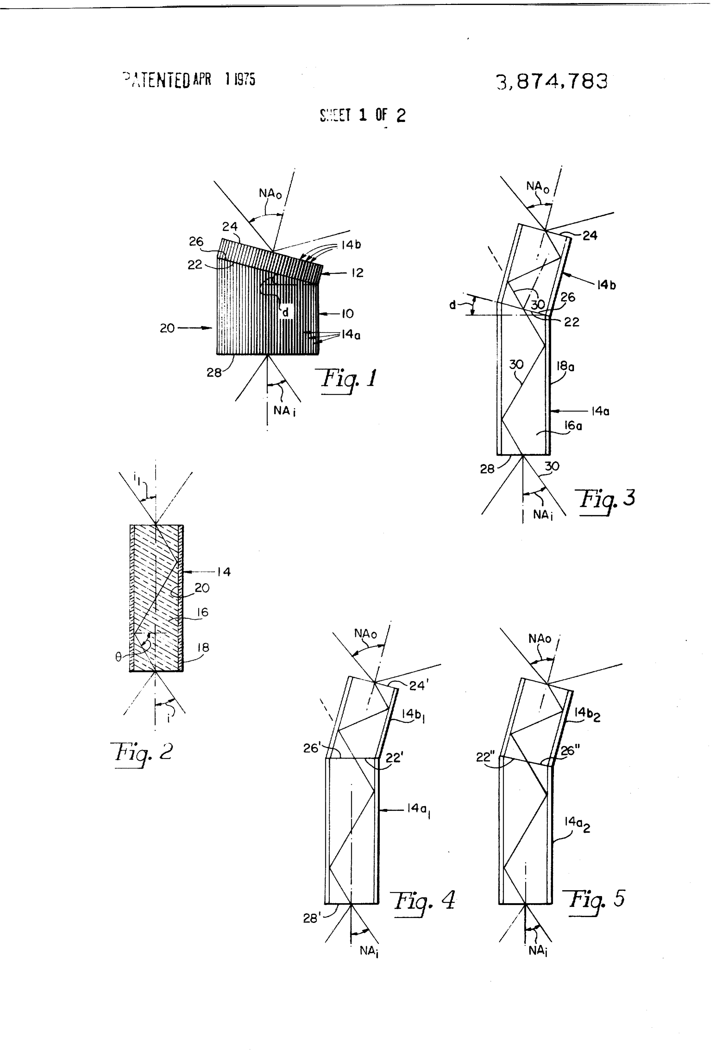
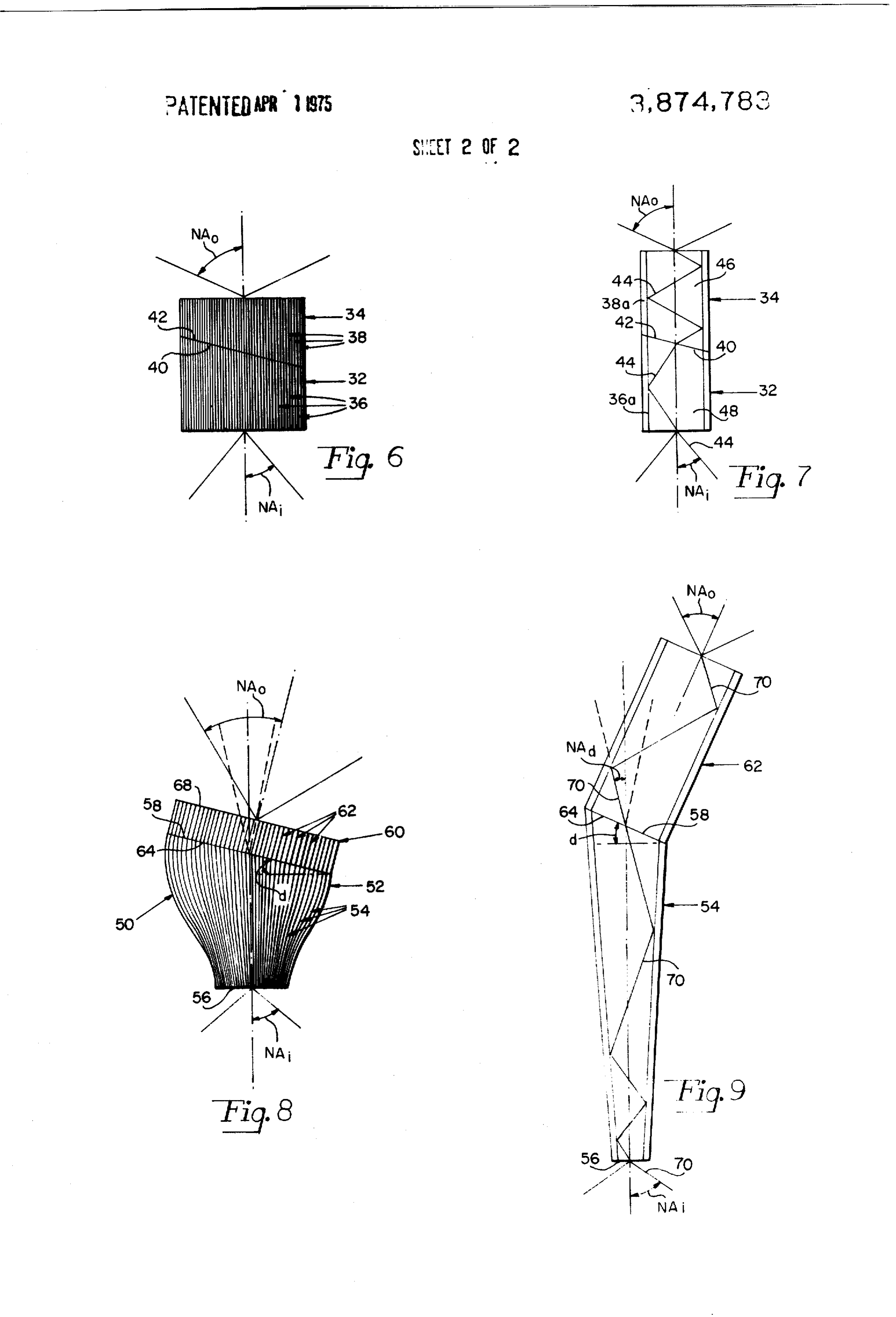
NUMERCA, APERTURE EXPANSON IN FBER FlcjS. 4 and 5 are diagrammatic cross-sectional views OPTIC DEVICES of interfacially coupled optical fibers illustrating mocli This is a continuation of application Ser. No. 277,7() fications of the FIG. 1 cmhodiment of the invention filed Aug. 2, 1972, now abandoned. als with all cross-section lines (mitted; FIG. 6 is a side elevational view of another modified
BACKGROUND OF THE INVENTION form of a coupled fiber optical element: 1. Field of the linvention Fli. 7 is an enlarged diagrammatic cross-sectional Fiber optics with particular reference to the expan view (without cross-section lines) of a pair of interfa sion of numerical aperture in fiber optical devices. cially coupled optical fibers schematically illustrating 2. Description of the Prior Art the function and operation of the FIG. 6 embodiment Fiber optic light and image-conducting devices conn of the invention;
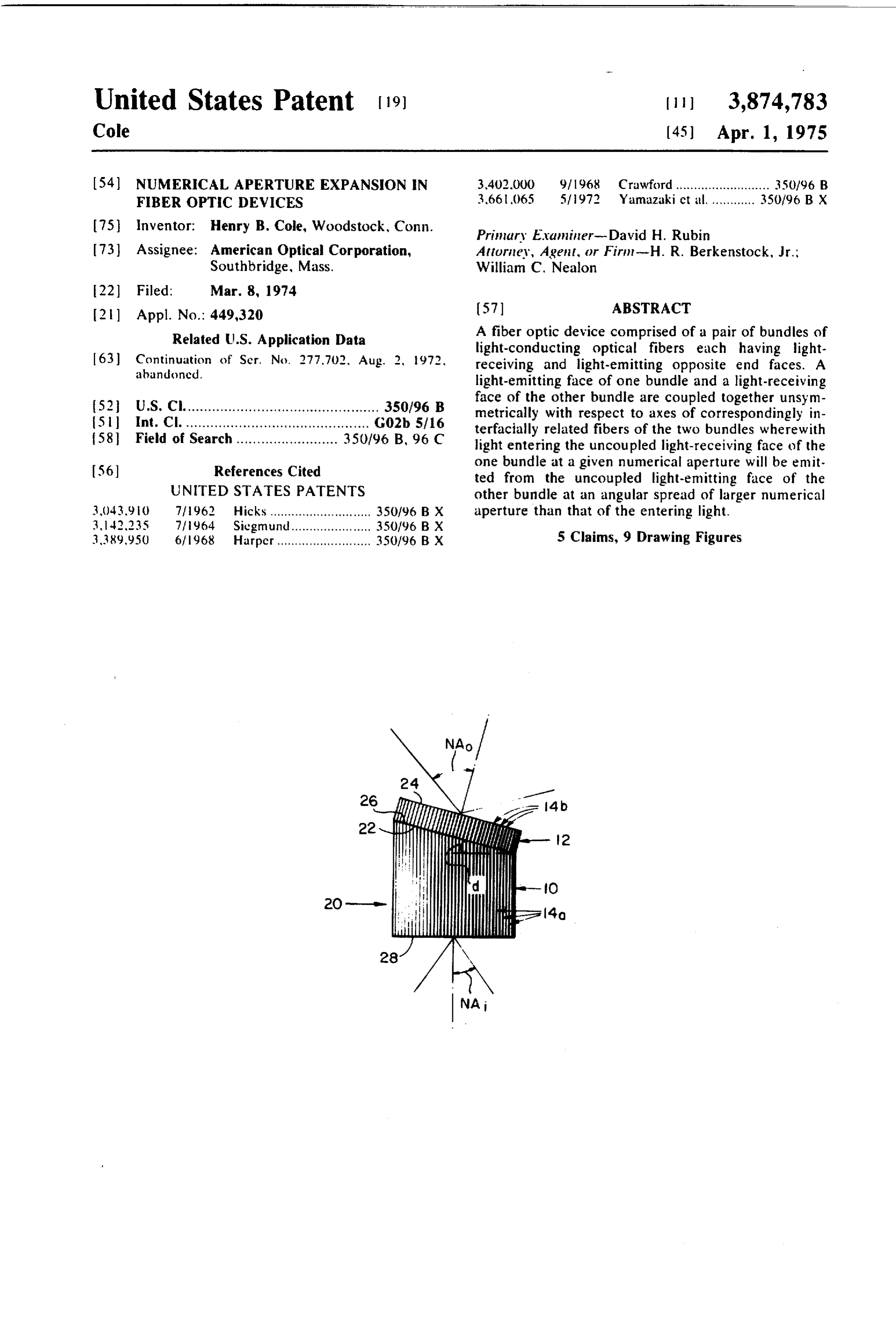
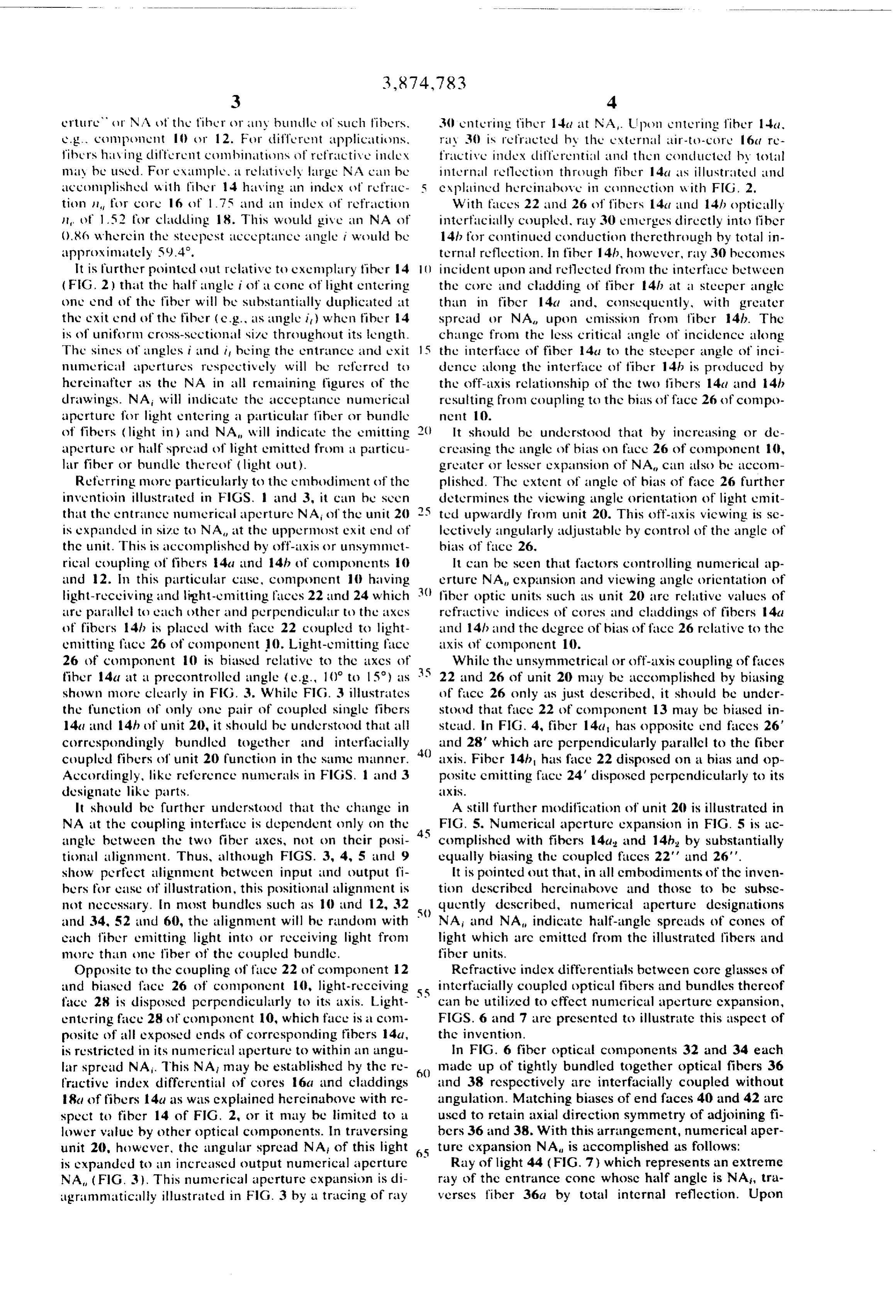
monly have relatively small output numerical apertures FIG. 8 is a side elevational view of still unother modi particularly when used as magnifiers and even more so fication of optical fiber components which are coupled when magnification is large, i.e., when the extent of together according to the present invention; and taper of the magnifying device is large. 5 FIG. 9 is an enlarged diagrammatic cross-sectional Light traversing tapered optical fibers inherently view of a pair of interficially coupled optical fibers continually reduces in numerical aperture as it tra schematically illustrating principles of operation of the verses the fibers from their small ends toward their FIG. 8 embodiment of the invention. larger ends. Thus, in fiber optic magnifiers, the viewing DESCRIPTION OF THE PREFERRED angle of output becomes progressively restricted in size EMBODIMENTS as the degree of magnification is increased. Further more, with the viewing angle centered on the axis of a FIG. 1 illustrates an interficially coupled pair of fiber fiber optic device as in the usual case, output of the de optic light-conducting components 10 and 12 where vice is awkwardly directed for some applications of use. with numerical aperture expansion is accomplished ac Viewing from above or directly in front of an image 5 cording to one aspect of the invention. Components 10 emitting device is often considerably less convenient and 12 each comprise a large number of light than off-axis viewing. conducting fibers all bundled tightly together with their Numerical perture expansion in other than tapered corresponding opposite ends forming light-receiving fiber optic light and image-conducting devices, making and light-cmitting opposite faces of each component. wicle angle and/or off-axis viewing possible, is highly Fiber 14 of FIG. 2 illustrates, in greatly enlarged scale, advantageous. In fiberscopes or in the control of bean the type of construction making up each of fibers 14a spreading with fiber optics in laser or conventional and 14h of components 1) and 12. In this connection, light-projecting lens systems for example, the capability fiber 14 has a core 16 of a relatively high refractive of controlling light spreading and viewing angle direc 35 index glass, plastic, quilrty or other light-conducting tion has considerable utility. The present invention core material. The core 16 is surrounded by a relatively makes this possible. thin cladding 18 of lower refractive index material which is intimately interfacially bonded to core 16.
SUMMARY OF THE INVENTION Light entering one end of fiber 14 within the critical Controlled numerical aperture expansion and orien angle of reflection of interface 20 between core 16 and tation of viewing angle in fiber optical light and inhage cladding 18 will transfer through fiber 14 according to transmitting devices in accomplished according to this the well known principles of total internal reflection. invention by off-axis coupling of fiber optic bundles Those interested in greater details of construction and where with the introduction of light from one hundle basic principles of operation of clad optical fibers per into another unsymmetrically with respect to the axis 45 se may refer to any one of U.S. Pat. Nos. 2,825,26(); of the other bundle results in a distribution or spreading 2,992,516; or 3,037,241.
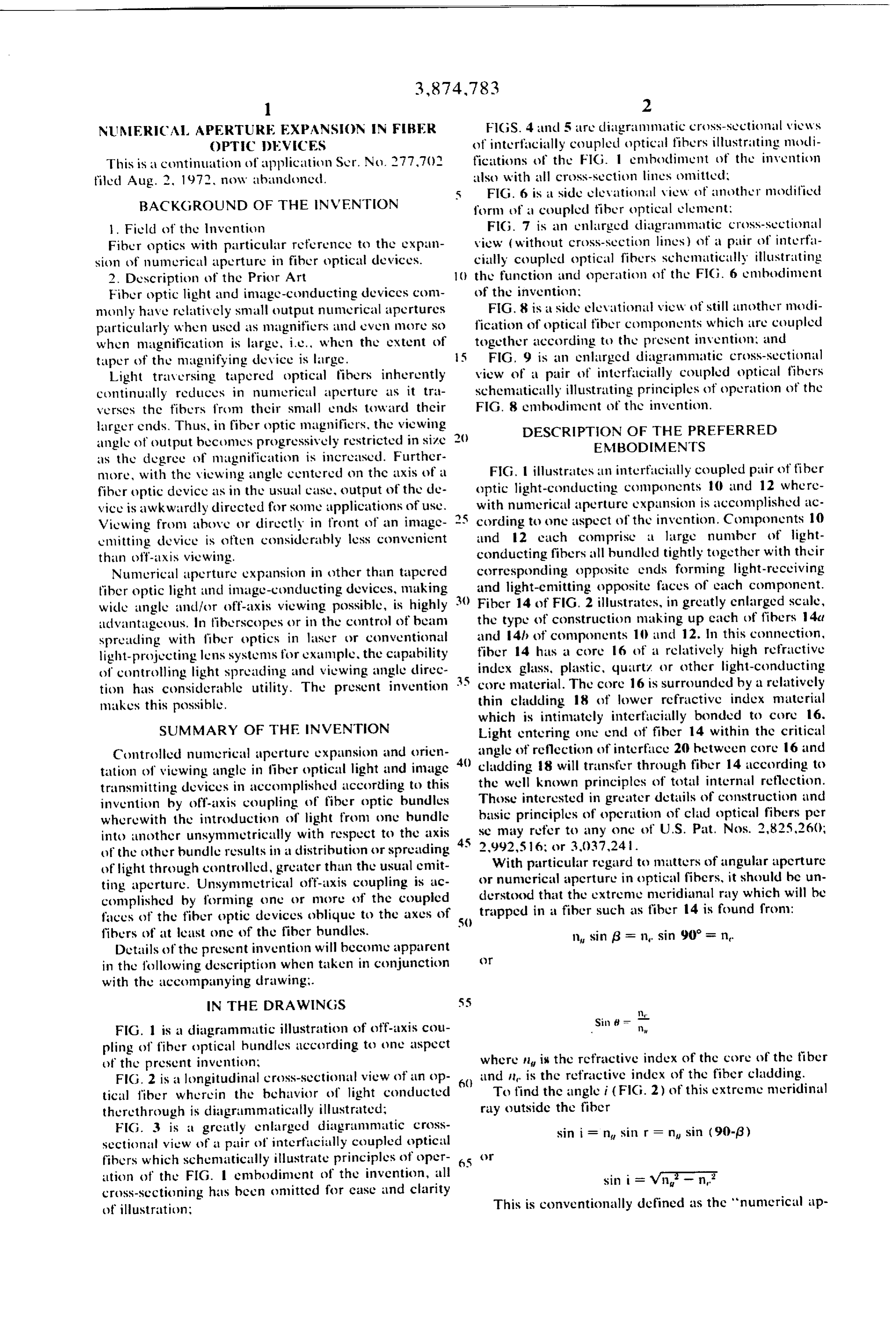
With particular regard to matters of angular aperture of light through controlled, greater than the usual emit ting aperture. Unsymmetrical off-axis coupling is ac or nunnerical aperture in optical fibers, it should be un complished by forming one or more of the coupled derstood that the extreme meridianal ray which will be faces of the fiber optic devices oblique to the axes of trapped in a fiber such as fiber 14 is found from: fibers of at least one of the fiber bundles. in sin (3 = , sin 90 = n, Details of the present invention will become apparent in the following description when taken in conjunction ()
with the accompanying drawing;.
FIG. 1 is a diagrammatic illustration of off-axis cou Sin pling of fiber optical hundles according to one aspect of the present invention; where n is the refractive index of the core of the fiber FIG. 2 is a longitudinal cross-sectional view of an op and it is the refractive index of the fiber cladding. tical liber wherein the behavior of light conducted To find the angle i (FIG. 2) of this extreme neridinal there through is diagrammatically illustrated; ray outside the fiber
FIG. 3 is a greatly enlarged diagrammatic cross sin i = n sin r = n sin (90-6) sectional view of a pair of interficially coupled optical fibers which schematically illustrate principles of oper 65 ( ution of the FIG. embodiment of the invention, all sin i = wn - n. cross-sectioning has been omitted for case and clarity of illustration; This is conventionally defined as the 'nunnerical ap
Page 5
erture NA it the fiher r any bundle of such fibers, 30 entering tiher 14a at NA. Upon entering fiber 14a. e.g., component () or 12. For different applications, Tily () is refracted hy the external air-to-core 16tt re fibers having clifferent combinations of refractive illex fractive index clifferential and then conducted by total may be used. For example, a relatively large NA can be internal reflection through fiber 14a as illustrated ind accomplished with fiber 14 having an index of refric explained herein above in connection with FIG, 2. tion a for core 16 of 1.75 and an index of refraction With faces 22 and 26 of fibers 14a and 14h optically it, of 1.52 for cladeling 18. This would give an NA of interficially coupled, ray 30 emerges directly into fiber ().86 wherein the steepest acceptance angle i would be 141 for continued conduction therethrough by total in approximately 59.4. ternal reflection. In fiber 14th, however, ray 30 becomes It is further pointed out relative to exemplary fiber 14 incident upon and reflected from the interface between (FIG. 2) that the half angle i of cone of light entering the core and cladding of fiber 14b at a steeper angle one end of the fiber will be substantially duplicated at than in fiber 14a and, consucculently, with greater the exit end of the fiber (e.g., as angle i, ) when fiber 14 spread or NA, upon emission from fiber 14b. The is of uniform cross-sectional size throughout its length. change from the less critical angle of incidence along The sines of angles i and it being the entrance and exit the interface of fiber 14a to the steeper angle of inci numerical apertures ruspectively will be referred to dence along the interface of fiber 14h is produced by hereinafter as the NA in all remaining figures of the the off-axis relationship of the two fibers 14a and 14th drawings. NA will inclicate the acceptance numerical resulting from coupling to the bias of face 26 of compo aperture for light entering a particular fibet ot bundle nent 10.
of fibers (light in ) and NA will indicate the emitting It should be understood that by increasing or de aperture or half spread of light emitted from a particu creasing the angle of bias on face 26 of component 10, lar fiber or bundle thereof (light out). greater or lesser expansion of NA can also be accom Referring more particularly to the enhdiment of the plished. The extent of angle of bias of face 26 further inventioin illustrated in FIGS. 1 and 3, it cun be seen determines the viewing angle orientation of light emit that the entrance numerical aperture NA of the unit 20 ted upwardly from unit 20. This off-axis viewing is se is expanded in size to NA, at the uppermost exit end of lectively angularly adjustable by control of the angle of the unit. This is accomplished by off-axis or unsymmet bias of face 26.
rical coupling of fibers 4a and 14h of components 10 It can be seen that factors controlling numerical ap and 12. In this particular case, component 10 having erture NA expansion and viewing angle oricntation of light-receiving and light-emitting faces 22 and 24 which fiber optic units such as unit 20 are relative values of are parallel to each other and perpendicular to the axes refractive indices of cores and claddings of fibers 4a of fibers 14h is placed with face 22 coupled to light and 141 and the degree of bias of face 26 relative to the emitting fice 26 of component 10. Light-emitting face axis of component 10.
26 of component 10 is biased relative to the axes of While the unsymmetrical or off-axis coupling of faces fiber 14a at a precontrolled angle (e.g., 10 to 15) as 35 22 and 26 of unit 20 may be accomplished by biasing shown more clearly in FIG. 3. While FIG. 3 illustrates of fice 26 only as just described, it should be under the function of only one pair of couplect single fibers stood that face 22 of component 13 may be biased in 4 tinct 4h funit 20, it should be understch() that all stead. In FIG. 4, fiber 14a has opposite end faces. 26' correspondingly bundled together and interfacially 40 and 28' which are perpendicularly parallel to the fiber coupled fibers of unit 20 function in the same manner. axis. Fiber 14h has face 22 disposed on a bias and op Accordingly, like reference numerals in FIGS. 1 and 3 posite emitting face 24' disposed perpendicularly to its designate like parts. axis.
It should be further understood that the change in A still further modification of unit 2 is illustrated in NA at the coupling interface is dependent only on the 45 FIG. S. Numerical aperture expansion in FIG. 5 is ac angle between the two fiber axcs, not on their posi complished with fibers 14a and 14h by substantially tional alignment. Thus, although FIGS. 3, 4, 5 and 9 equally biasing the coupled fices 22' and 26'. show perfect alignment between input ind output fi It is pointed out that, in all cmbodiments of the inven bers for case of illustration, this positional alignment is tion described hercinbove and those to be subsc not necessary. In most bundles such as 10 and 12, 32 quently described, numerical aperture designations and 34, 52 and 60, the alignment will he random with 5) NA, and NA indicate half-angle spreads of cones of each fiber emitting light into or receiving light from light which are emitted from the illustrated fibers and more thin the fiber of the coupled bundle. fiber units.
Opposite to the coupling of face 22 of component 12 Refractive index differentials between core glasses of and biased face 26 of coniponent 10, light-receiving 55 interfacially coupled optical fibers and bundles thereof face 28 is disposed perpendicularly to its axis. Light can be utilized to effect numerical aperture expansion, entering face 28 of component 10, which face is a conn FIGS. 6 and 7 are presented to illustrate this aspect of posite of all exposed ends of corresponding fibers 14a, the inventin.
is restricted in its numerical aperture to within an angu In FIG. 6 fiber optical components 32 and 34 each lar spread NA. This NA may be established by the re made up of tightly bundled together optical fibers 36 fractive index differential of cores 6a and claddings and 38 respectively are interfacially coupled without 18a of fibers 14a as was explained hereinabove with re angulation. Matching biases of end faces 40 and 42 are spect to fiber 14 of FIG. 2, or it may be limited to a used to retain axial direction symmetry of adjoining fi lower value by other optical components. In traversing bers 36 and 38. With this arrangement, numerical aper unit 20, however, the angular spread NAi of this light 65 ture expansion NA is accomplished as follows: is expanded to an increased output numerical aperture Ray of light 44 (FIG. 7) which represents an extreme NA, (FIG. 3). This numerical aperture expansion is di ray of the entrance conc whose half angle is NA, tra agrammatically illustrated in FIG. 3 by a tracing of ray verses fiber 36a by total internal reflection. Upon
Page 6
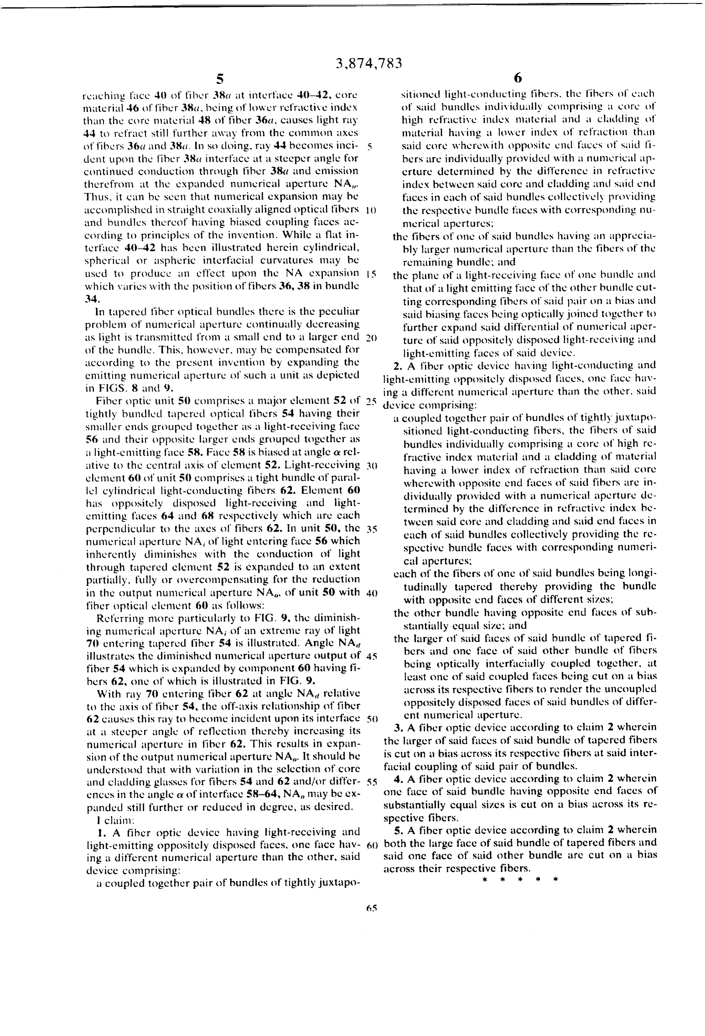
S 6 reaching face 40 of fiber 38c at interface 40-42, core sitioned light-conducting fibers, the fibers of each material 46 of fiber 38a, being (flower refractive index of said huncles inclividually comprising : core of than the core material 48 of fiber 36a, causes light ray high refractive inclux material and a cladding of 44 to refract still further away from the common axes material having a lower index of refraction than of fibers 36a and 38.1. In su doing, ray 44 becomes inci said core where with opposite lenc fices of said fi dent upon the fiber 38a interface at a steeper angle for bers are individually provided with a numerical ap continued conduction through fiber 38a and emission crture determined by the difference in refractive there from at the expanded numerical aperture NA. index between said core and cladding und said end Thus, it can be seen that numerical expansion may he faces in each of saic bundles collectively providing accomplished in straight colxially aligned optical fibers the respective bundle faces with corresponding nu and buncles thereof having biased coupling faces ac merical apertures;
cording to principles of the invention. While a flat in the fibers of one of said huncles having an upprecial terface 40-42 has been illustrated herein cylindrical, bly larger numerical aperture than the fibers of the spherical or aspheric interfacial curvatures may be remaining bundle; and used to produce an effect upon the NA expansion 5 the plane of a light-receiving face of one bundle and which varies with the position of fibers 36, 38 in bundle that of a light emitting face of the other bundle cut 34. ting corresponding fibers of said pair on a hias and in tapered fiber optical bundles there is the peculiar said biasing faces being optically joined together to problem of numerical aperture continually decreasing further expand said differential of numerical aper as light is transmitted from a small end to a larger end ture of said oppositely disposed light-receiving and of the hundle. This, however, may be compensated for light-emitting faces of said device. according to the present invention by expanding the 2. A fiber optic device having light-conducting and emitting numerical aperture of such a unit as depicted light-emitting oppositely disposed faces, one fice hav in FGS. 8 and 9. ing a different numerical aperture than the other, said Fiber optic unit 50 comprises a major element 52 of 5 device comprising:
tightly bundled tapered optical fibers 54 having their a coupled together pair of bundles of tightly juxtapo smaller encls grouped together as a light-receiving face sitioned light-conducting fibers, the fibers of said 56 and their opposite larger ends grouped together as bundles individually comprising a core of high re a light-emitting face 58. Face 58 is hiased at angle a rel fractive index material and a cladding of material ative to the central axis of element 52. Light-receiving 3) having a lower index of refraction than said core element 60 of unit 50 comprises a tight bundle of paral where with opposite end faces of said fibers are in lel cylindrical light-conducting fibers 62. Element 60 dividually provicled with a numerical aperture cle has oppositely disposed light-receiving and light termined by the difference in refractive index be emitting faces 64 and 68 respectively which are each tween saic core and cladding and said end faces in perpendicular to the axes of fibers 62. In unit 50, the each of said bundles collectively providing the re numerical aperture NA of light entering face 56 which spective bundle faces with corresponding nunneri inherently diminishes with the conduction of light cal apertures;
through tapered element 52 is expanded to an extent each of the fibers of one of said bundles being longi partially, fully or overcompensating for the reduction tudinally tapered thereby providing the bundle in the output numerical aperture NA of unit 50 with with opposite end faces of different sizes; fiber optical element 60 as follows: the other bundle having opposite end faces of sub Referring more particularly to FIG. 9, the diminish stantially equal size; and ing numerical aperture NAi of an extreme ray of light the larger of said faces of said bundle of tapered fi 70 entering tapered fiber 54 is illustrated. Angle NA bers and onc face of said other buncle of fibers illustrates the diminished numerical aperture output of 45 being optically interfacially coupled together, at fiber 54 which is expanded by component 60 having fi bers 62, one of which is illustrated in FIG. 9. least one of said coupled faces being cut on a bias With ray 70 entering fiber 62 at angle NA relative across its respective fibers to render the uncoupled to the axis of fiber 54, the off-axis relationship of fiber oppositely disposed faces of said bundles of differ 62 causes this ray to become incident upon its interface 5) ent numerical perture.
at a steeper angle of reflection thereby increasing its 3. A fiber optic device according to claim 2 wherein numerical aperture in fiber 62. This results in expan the larger of said faces of said bundle of tapered fibers sion of the output numerical aperture NA. It should he is cut on a bias across its respective fibers at said inter understood that with variation in the selection of core facial coupling of said pair of bundles. and cladding glasses for fibers 54 and 62 and/or differ 55 4. A fiber optic device according to claim 2 wherein ences in the angle cy of interface 58-64, NA may be ex one face of said bundle having opposite end faces of panded still further or reduced in degree, as desired. substantially cqual sizes is cut on a bias across its re l claim: spective fibers.
1. A fiher optic device having light-receiving and 5. A fiber optic device according to claim 2 wherein light-emitting oppositely disposed faces, onc face hav 6) both the large face of said bundle of tapered fibers and ing a different numerical aperture than the other, said said onc face of said other bundle are cut on a bias device comprising: across their respective k fibers.
a coupled together pair of bundles of tightly juxtapo
Provenance
- Collection
- Cited prior art
- Original PDF
- patentimages.storage.googleapis.com →
- Filed
- 1974-03-08
- Pages
- 6
- Method
- pdftotext (the PDF's own text layer) + pdftoppm 300dpi page scans
- Source
- Google Patents bibliographic record
- Granted
- 1975-04-01
- Inventors
- Henry B Cole; American Optical Corp
- Transcribed from
- patentimages.storage.googleapis.com →