patent · US4375380
Process and installation for manufacturing a photothermal converter apparatus
1 March 1983
Page 1 — bibliographic record
3. f : 33 x2 as 375 g 38 ()
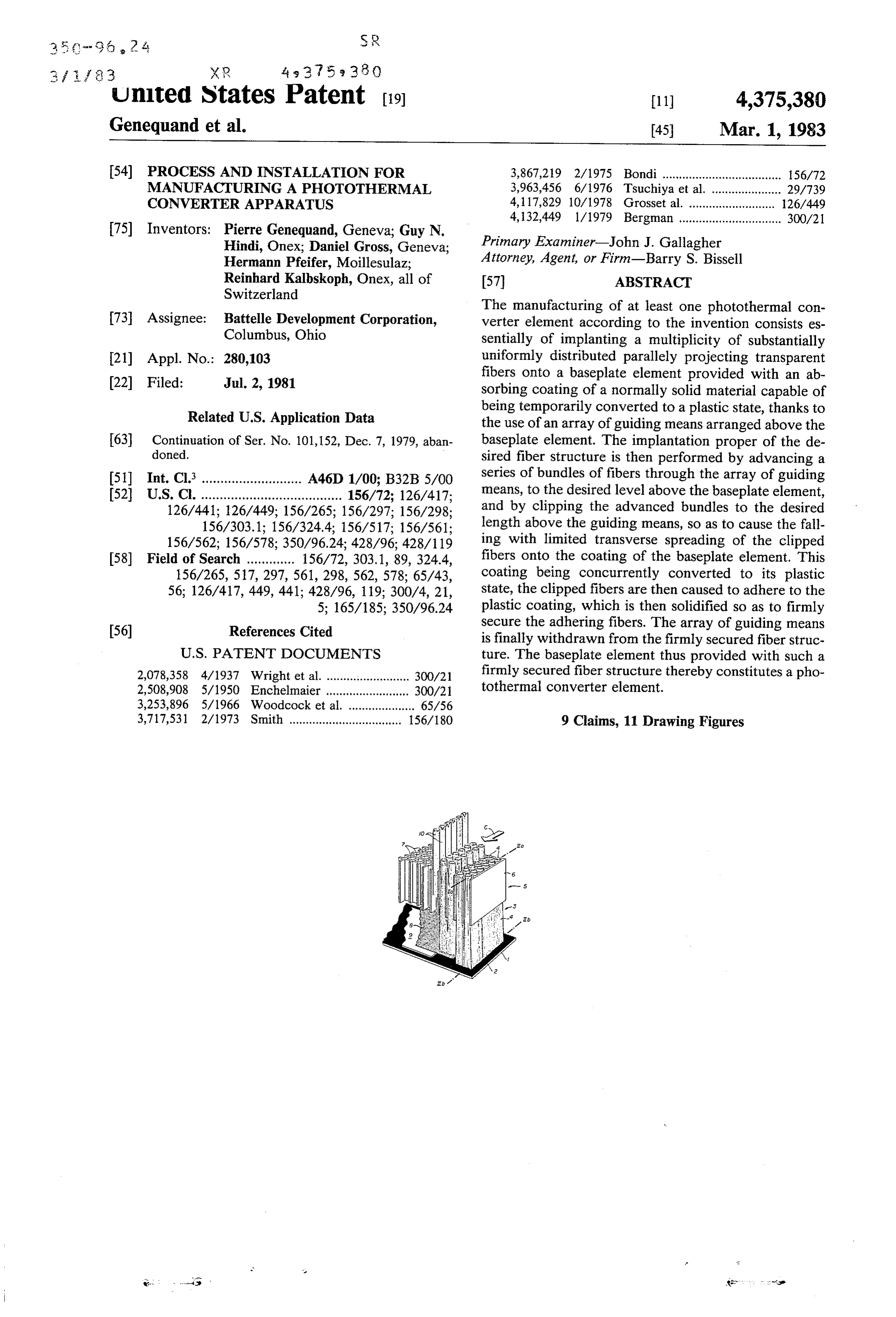
United States Patent (19) 11) 4,375,380 Genequand et al. 45) Mar. 1, 1983 54) PROCESS AND INSTALLATION FOR 3,867,219 2/1975 Bondi .................................... 156/72 MANUFACTURING A PHOTOTHERMAL 3,963,456 6/1976 Tsuchiya et al. ..................... 29/739 CONVERTER APPARATUS 4,117,829 10/1978 Grosset al. .......................... 26/449 4,132,449 1/1979 Bergman ........ ................ 300/21 75 Inventors: Pierre Genequand, Geneva; Guy N.
Hindi, Onex; Daniel Gross, Geneva; Primary Examiner-John J. Gallagher
Hermann Pfeifer, Moillesulaz; Attorney, Agent, or Firm-Barry S. Bissell
Reinhard Kalbskoph, Onex, all of 57 ABSTRACT
Switzerland
The manufacturing of at least one photothermal con 73 Assignee: Battelle Development Corporation, verter element according to the invention consists es Columbus, Ohio sentially of implanting a multiplicity of substantially 21 Appl. No.: 280,103 uniformly distributed parallely projecting transparent fibers onto a baseplate element provided with an ab (22 Filed: Jul. 2, 1981 sorbing coating of a normally solid material capable of being temporarily converted to a plastic state, thanks to
Related U.S. Application Data the use of an array of guiding means arranged above the 63 Continuation of Ser. No. 101,152, Dec. 7, 1979, aban baseplate element. The implantation proper of the de doned. sired fiber structure is then performed by advancing a 51) Int. Cl............................ A46D 1/00; B32B5/00 series of bundles of fibers through the array of guiding 52 U.S. C. ...................................... 156/72; 126/417; means, to the desired level above the baseplate element, 126/441; 126/449; 156/265; 156/297; 156/298; and by clipping the advanced bundles to the desired 156/303.1; 156/324.4; 156/517; 156/561; length above the guiding means, so as to cause the fall 156/562; 156/578; 350/96.24; 428/96; 428/119 ing with limited transverse spreading of the clipped 58) Field of Search ............. 156/72, 303.1, 89, 324.4, fibers onto the coating of the baseplate element. This 156/265, 517, 297,561, 298, 562, 578; 65/43, coating being concurrently converted to its plastic 56; 126/417, 449, 441; 428/96, 119; 300/4, 21, state, the clipped fibers are then caused to adhere to the 5; 165/185; 350/96.24 plastic coating, which is then solidified so as to firmly 56) References Cited secure the adhering fibers. The array of guiding means is finally withdrawn from the firmly secured fiber struc
2,078,358 4/1937 Wright et al.................. ... 300/21 firmly secured fiber structure thereby constitutes a pho 2,508,908 5/1950 Enchelmaier ..... ... 300/21 tothermal converter element.
3,253,896 5/1966 Woodcock et al. -O - 65/56
3,717,531 2/1973 Smith .................................. 156/18O 9 Claims, 11 Drawing Figures
tr. is use
Page 2
Drawing sheet — no readable text.
Page 3
Drawing sheet — no readable text.
Page 4
Drawing sheet — no readable text.
Page 5
Drawing sheet — no readable text.
Page 6
Drawing sheet — no readable text.
Page 7
PROCESS AND INSTALLATION FOR
FIG. 10 is a front end view similar to FIG.4, showing a second variation.
MANUFACTURING A PHOTOTHERMAL The process according to the invention for manufac CONVERTER APPARATUS turing at least one photothermal converter element 5 consists essentially of implanting a multiplicity of sub
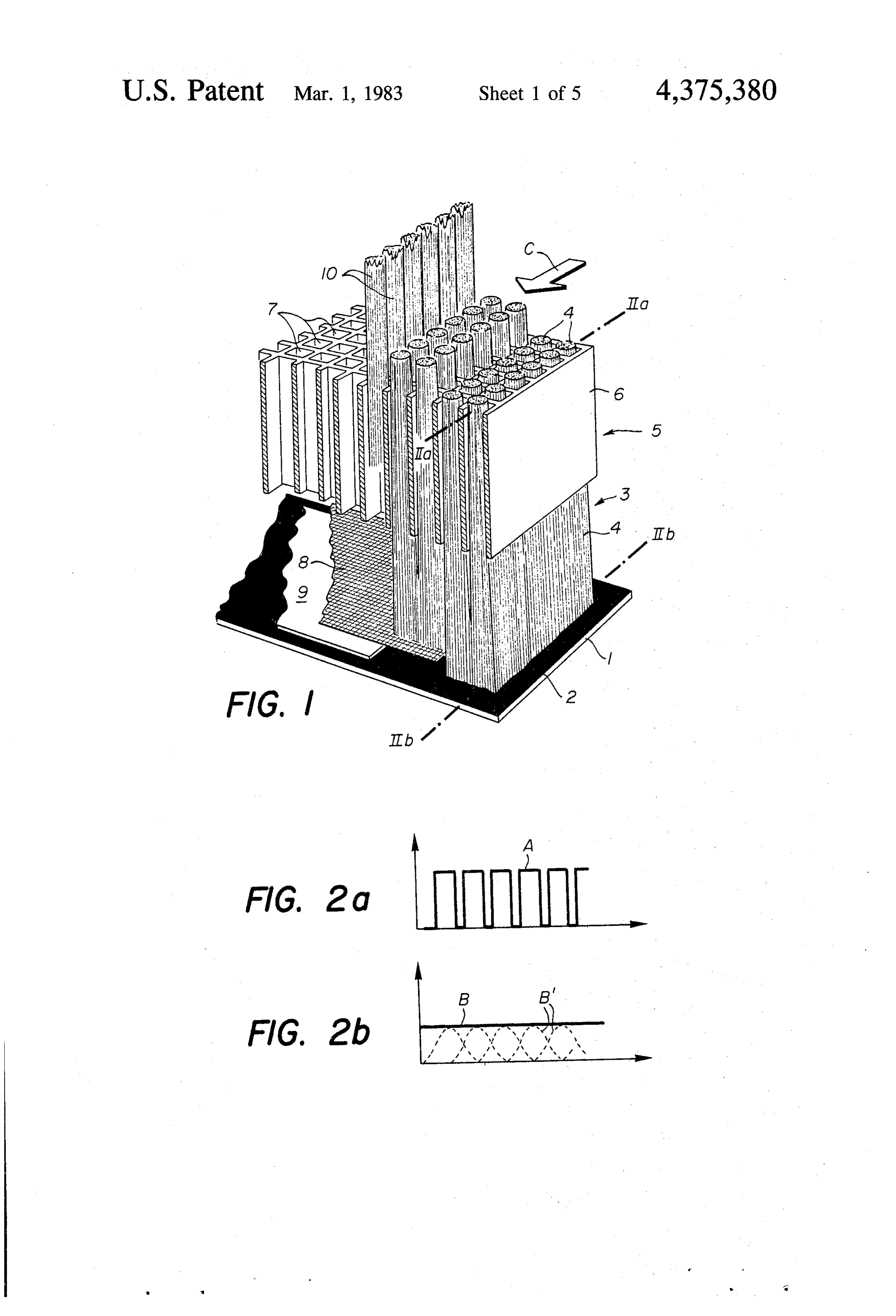
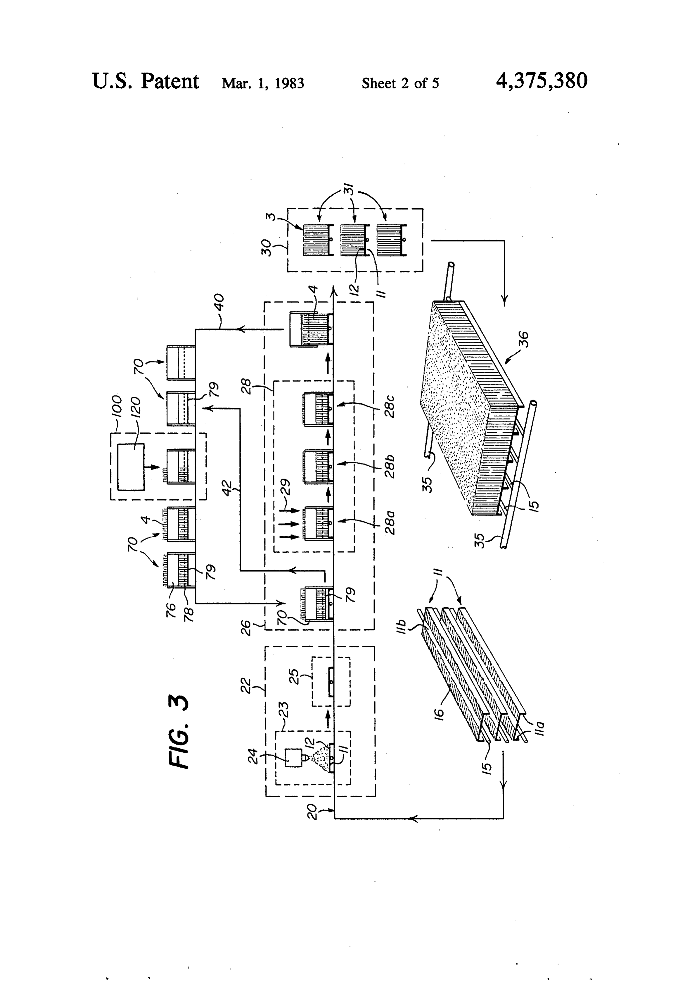
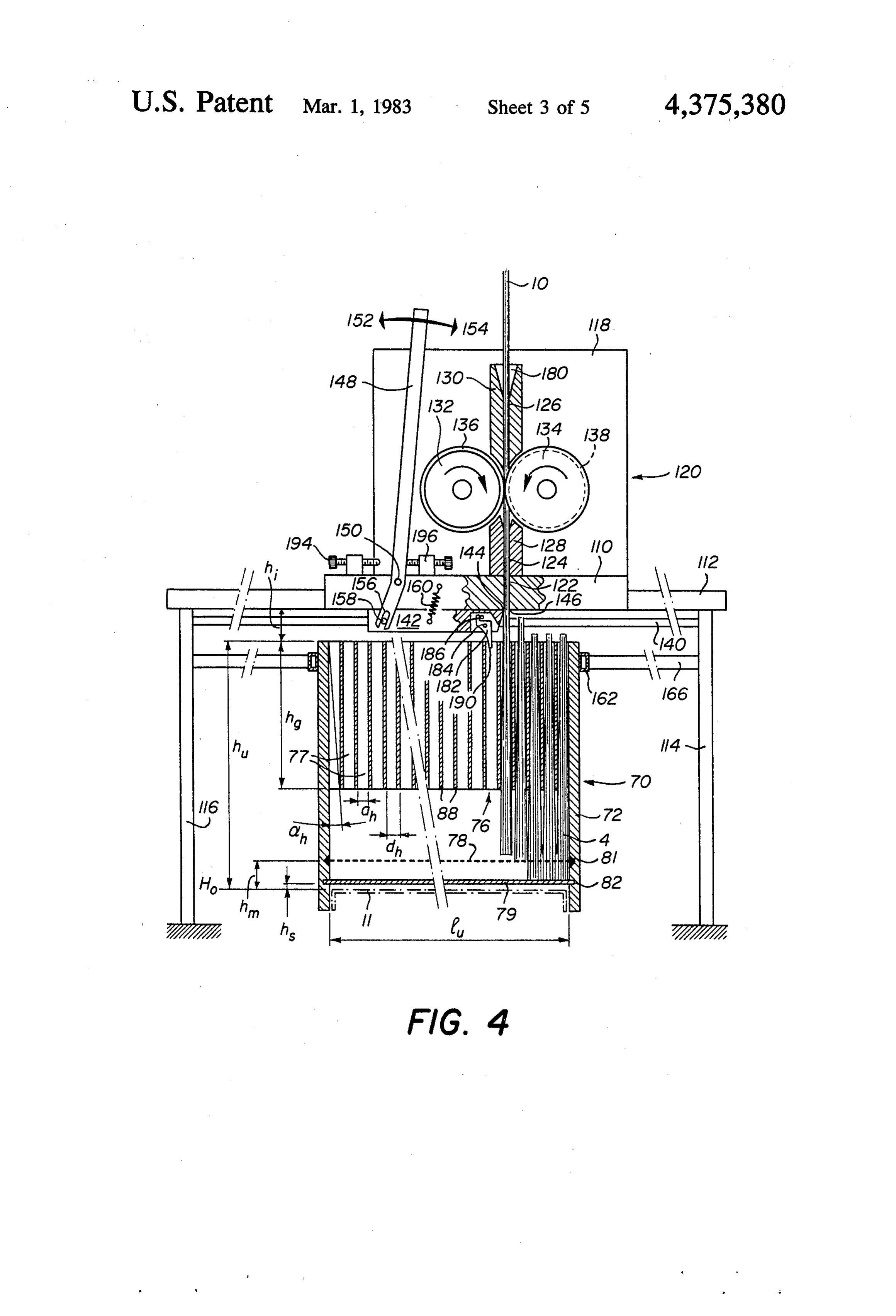
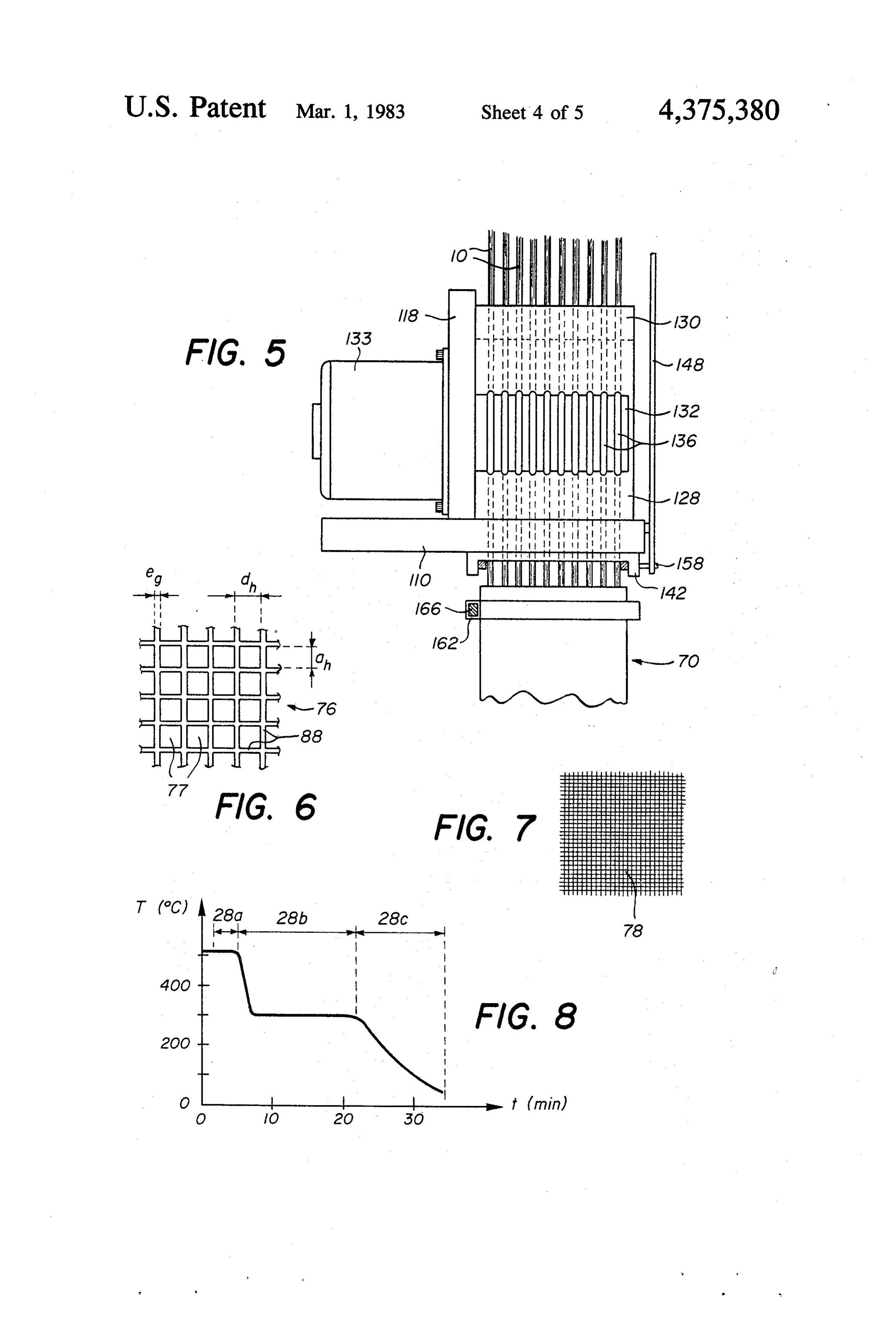
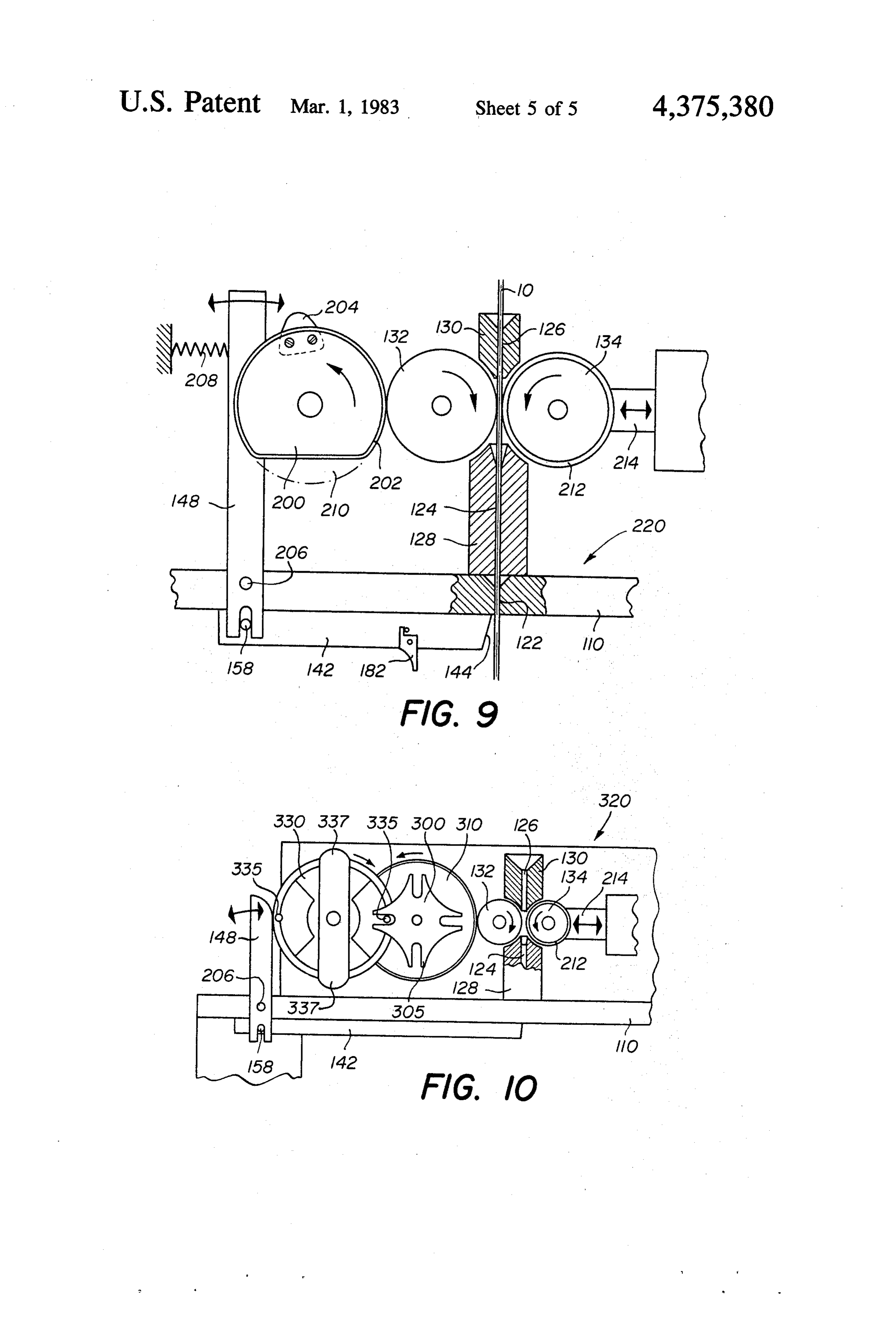
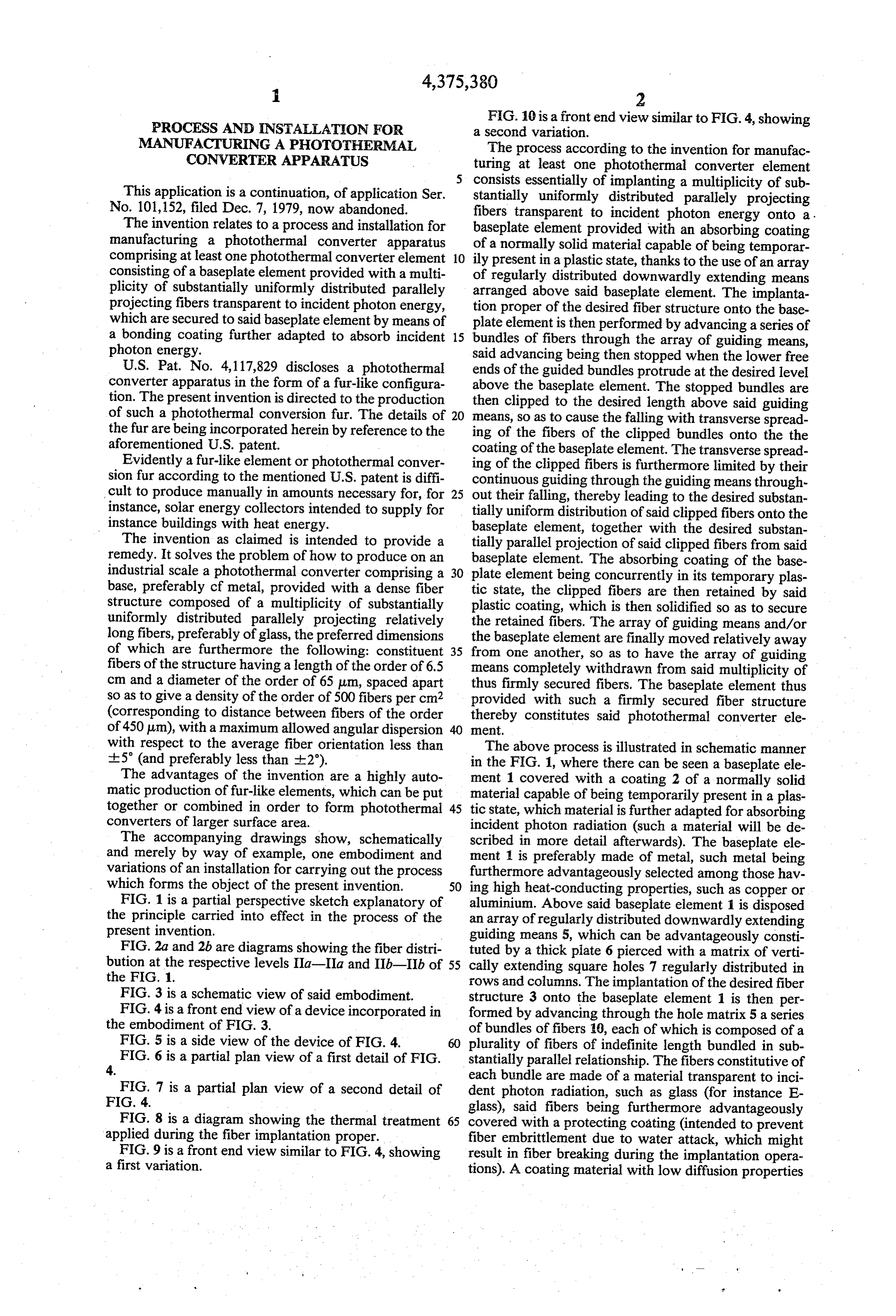
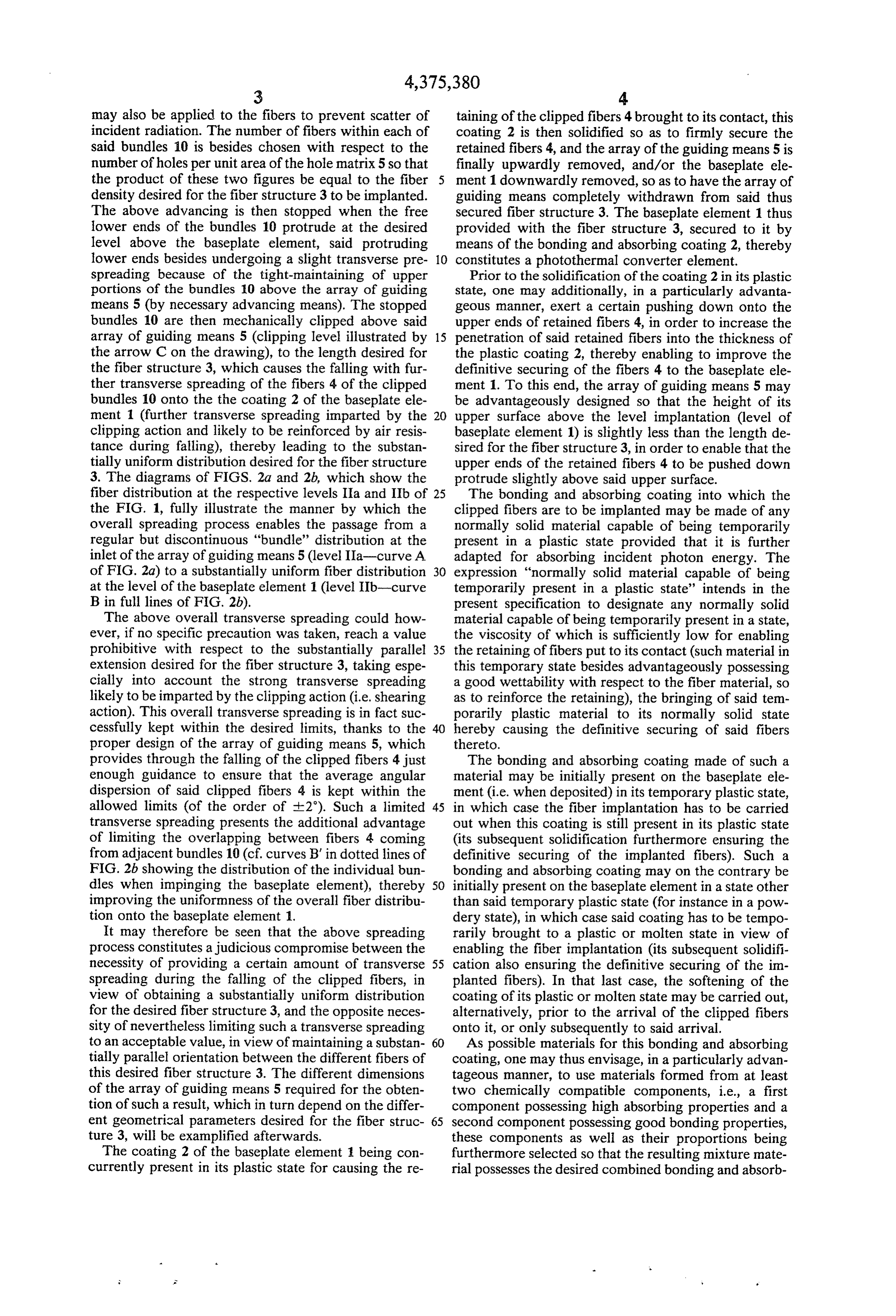
This application is a continuation, of application Ser. stantially uniformly distributed parallely projecting No. 101,152, filed Dec. 7, 1979, now abandoned. fibers transparent to incident photon energy onto a . The invention relates to a process and installation for baseplate element provided with an absorbing coating manufacturing a photothermal converter apparatus of a normally solid material capable of being temporar comprising at least one photothermal converter element 10 ily present in a plastic state, thanks to the use of an array consisting of a baseplate element provided with a multi of regularly distributed downwardly extending means plicity of substantially uniformly distributed parallely arranged above said baseplate element. The implanta projecting fibers transparent to incident photon energy, tion proper of the desired fiber structure onto the base which are secured to said baseplate element by means of plate element is then performed by advancing a series of a bonding coating further adapted to absorb incident 15 bundles of fibers through the array of guiding means, photon energy. said advancing being then stopped when the lower free U.S. Pat. No. 4,117,829 discloses a photothermal ends of the guided bundles protrude at the desired level converter apparatus in the form of a fur-like configura above the baseplate element. The stopped bundles are tion. The present invention is directed to the production then clipped to the desired length above said guiding of such a photothermal conversion fur. The details of 20 means, so as to cause the falling with transverse spread the fur are being incorporated herein by reference to the ing of the fibers of the clipped bundles onto the the aforementioned U.S. patent. coating of the baseplate element. The transverse spread Evidently a fur-like element or photothermal conver ing of the clipped fibers is furthermore limited by their sion fur according to the mentioned U.S. patent is diffi continuous guiding through the guiding means through cult to produce manually in amounts necessary for, for 25 out their falling, thereby leading to the desired substan instance, solar energy collectors intended to supply for tially uniform distribution of said clipped fibers onto the instance buildings with heat energy. baseplate element, together with the desired substan The invention as claimed is intended to provide a tially parallel projection of said clipped fibers from said remedy. It solves the problem of how to produce on an baseplate element. The absorbing coating of the base industrial scale a photothermal converter comprising a 30 plate element being concurrently in its temporary plas base, preferably cf metal, provided with a dense fiber tic state, the clipped fibers are then retained by said structure composed of a multiplicity of substantially plastic coating, which is then solidified so as to secure uniformly distributed parallely projecting relatively the retained fibers. The array of guiding means and/or long fibers, preferably of glass, the preferred dimensions the baseplate element are finally moved relatively away of which are furthermore the following: constituent 35 from one another, so as to have the array of guiding fibers of the structure having a length of the order of 6.5 means completely withdrawn from said multiplicity of cm and a diameter of the order of 65 um, spaced apart thus firmly secured fibers. The baseplate element thus so as to give a density of the order of 500 fibers per cm2 provided with such a firmly secured fiber structure (corresponding to distance between fibers of the order thereby constitutes said photothermal converter ele of 450 um), with a maximum allowed angular dispersion ment, with respect to the average fiber orientation less than The above process is illustrated in schematic manner --5 (and preferably less than +2). in the FIG. 1, where there can be seen a baseplate ele The advantages of the invention are a highly auto ment 1 covered with a coating 2 of a normally solid matic production of fur-like elements, which can be put material capable of being temporarily present in a plas together or combined in order to form photothermal 45 tic state, which material is further adapted for absorbing converters of larger surface area. incident photon radiation (such a material will be de The accompanying drawings show, schematically scribed in more detail afterwards). The baseplate ele and merely by way of example, one embodiment and ment 1 is preferably made of metal, such metal being variations of an installation for carrying out the process furthermore advantageously selected among those hav which forms the object of the present invention. 50 ing high heat-conducting properties, such as copper or FIG. 1 is a partial perspective sketch explanatory of aluminium. Above said baseplate element 1 is disposed the principle carried into effect in the process of the an array of regularly distributed downwardly extending present invention. guiding means 5, which can be advantageously consti FIG.2a and 2b are diagrams showing the fiber distri tuted by a thick plate 6 pierced with a matrix of verti bution at the respective levels IIa-IIa and IIb-IIb of 55 cally extending square holes 7 regularly distributed in the FIG. 1. rows and columns. The implantation of the desired fiber FIG. 3 is a schematic view of said embodiment. structure 3 onto the baseplate element 1 is then per FIG. 4 is a front end view of a device incorporated in formed by advancing through the hole matrix 5 a series the embodiment of FIG. 3. of bundles of fibers 10, each of which is composed of a FIG. 5 is a side view of the device of FIG. 4. 60 plurality of fibers of indefinite length bundled in sub FIG. 6 is a partial plan view of a first detail of FIG. stantially parallel relationship. The fibers constitutive of
each bundle are made of a material transparent to inci
FIG. 7 is a partial plan view of a second detail of dent photon radiation, such as glass (for instance E FIG. 4. glass), said fibers being furthermore advantageously FIG. 8 is a diagram showing the thermal treatment 65 covered with a protecting coating (intended to prevent applied during the fiber implantation proper. fiber embrittlement due to water attack, which might FIG. 9 is a front end view similar to FIG. 4, showing result in fiber breaking during the implantation opera a first variation. tions). A coating material with low diffusion properties
Page 8
may also be applied to the fibers to prevent scatter of taining of the clipped fibers 4 brought to its contact, this incident radiation. The number of fibers within each of coating 2 is then solidified so as to firmly secure the said bundles 10 is besides chosen with respect to the retained fibers 4, and the array of the guiding means 5 is number of holes per unit area of the hole matrix 5 so that finally upwardly removed, and/or the baseplate ele the product of these two figures be equal to the fiber ment 1 downwardly removed, so as to have the array of density desired for the fiber structure 3 to be implanted. guiding means completely withdrawn from said thus The above advancing is then stopped when the free secured fiber structure 3. The baseplate element 1 thus lower ends of the bundles 10 protrude at the desired provided with the fiber structure 3, secured to it by level above the baseplate element, said protruding means of the bonding and absorbing coating 2, thereby lower ends besides undergoing a slight transverse pre 10 constitutes a photothermal converter element. spreading because of the tight-maintaining of upper Prior to the solidification of the coating 2 in its plastic portions of the bundles 10 above the array of guiding state, one may additionally, in a particularly advanta means 5 (by necessary advancing means). The stopped geous manner, exert a certain pushing down onto the bundles 10 are then mechanically clipped above said upper ends of retained fibers 4, in order to increase the array of guiding means 5 (clipping level illustrated by 15 penetration of said retained fibers into the thickness of the arrow C on the drawing), to the length desired for the plastic coating 2, thereby enabling to improve the the fiber structure 3, which causes the falling with fur definitive securing of the fibers 4 to the baseplate ele ther transverse spreading of the fibers 4 of the clipped ment 1. To this end, the array of guiding means 5 may bundles 10 onto the the coating 2 of the baseplate ele be advantageously designed so that the height of its ment 1 (further transverse spreading imparted by the 20 upper surface above the level implantation (level of clipping action and likely to be reinforced by air resis baseplate element 1) is slightly less than the length de tance during falling), thereby leading to the substan sired for the fiber structure 3, in order to enable that the tially uniform distribution desired for the fiber structure upper ends of the retained fibers 4 to be pushed down 3. The diagrams of FIGS. 2a and 2b, which show the protrude slightly above said upper surface. fiber distribution at the respective levels IIa and IIb of 25 The bonding and absorbing coating into which the the FIG. 1, fully illustrate the manner by which the clipped fibers are to be implanted may be made of any overall spreading process enables the passage from a normally solid material capable of being temporarily regular but discontinuous "bundle' distribution at the present in a plastic state provided that it is further inlet of the array of guiding means 5 (level IIa-curve A adapted for absorbing incident photon energy. The of FIG. 2a) to a substantially uniform fiber distribution 30 expression "normally solid material capable of being at the level of the baseplate element 1 (level IIb-curve temporarily present in a plastic state' intends in the B in full lines of FIG. 2b). present specification to designate any normally solid The above overall transverse spreading could how material capable of being temporarily present in a state, ever, if no specific precaution was taken, reach a value the viscosity of which is sufficiently low for enabling prohibitive with respect to the substantially parallel 35 the retaining of fibers put to its contact (such material in extension desired for the fiber structure 3, taking espe this temporary state besides advantageously possessing cially into account the strong transverse spreading a good wettability with respect to the fiber material, so likely to be imparted by the clipping action (i.e. shearing as to reinforce the retaining), the bringing of said tem action). This overall transverse spreading is in fact suc porarily plastic material to its normally solid state cessfully kept within the desired limits, thanks to the 40 hereby causing the definitive securing of said fibers proper design of the array of guiding means 5, which thereto.
provides through the falling of the clipped fibers 4 just The bonding and absorbing coating made of such a enough guidance to ensure that the average angular material may be initially present on the baseplate ele dispersion of said clipped fibers 4 is kept within the ment (i.e. when deposited) in its temporary plastic state, allowed limits (of the order of -2). Such a limited 45 in which case the fiber implantation has to be carried transverse spreading presents the additional advantage out when this coating is still present in its plastic state of limiting the overlapping between fibers 4 coming (its subsequent solidification furthermore ensuring the from adjacent bundles 10 (cf. curves B' in dotted lines of definitive securing of the implanted fibers). Such a FIG.2b showing the distribution of the individual bun bonding and absorbing coating may on the contrary be dles when impinging the baseplate element), thereby 50 initially present on the baseplate element in a state other improving the uniformness of the overall fiber distribu than said temporary plastic state (for instance in a pow tion onto the baseplate element 1. dery state), in which case said coating has to be tempo It may therefore be seen that the above spreading rarily brought to a plastic or molten state in view of process constitutes a judicious compromise between the enabling the fiber implantation (its subsequent solidifi necessity of providing a certain amount of transverse 55 cation also ensuring the definitive securing of the in spreading during the falling of the clipped fibers, in planted fibers). In that last case, the softening of the view of obtaining a substantially uniform distribution coating of its plastic or molten state may be carried out, for the desired fiber structure 3, and the opposite neces alternatively, prior to the arrival of the clipped fibers sity of nevertheless limiting such a transverse spreading onto it, or only subsequently to said arrival. to an acceptable value, in view of maintaining a substan 60 As possible materials for this bonding and absorbing tially parallel orientation between the different fibers of coating, one may thus envisage, in a particularly advan this desired fiber structure 3. The different dimensions tageous manner, to use materials formed from at least of the array of guiding means 5 required for the obten two chemically compatible components, i.e., a first tion of such a result, which in turn depend on the differ component possessing high absorbing properties and a ent geometrical parameters desired for the fiber struc 65 second component possessing good bonding properties, ture 3, will be examplified afterwards. these components as well as their proportions being The coating 2 of the baseplate element 1 being con furthermore selected so that the resulting mixture mate currently present in its plastic state for causing the re rial possesses the desired combined bonding and absorb
Page 9
ing properties. In a preferred manner, such a resulting use a mixture material comprising as bonding compo mixture material will be designed so that the bonding nent, a solder glass (for instance a solder glass commer component constitutes the major part, the absorbing cialized under the trademark SCHOTT 8471), and as component being then incorporated as an additive in the absorbing component, a black decorating glass compris body of the bonding component. ing oxides of at least one metal selected within the As bonding component capable of enabling the re group Mn, Fe, Co, Ni (for instance a black decorating sulting mixture material to be temporarily present in a glass commercialized under the trademark DEGUSSA. plastic state, one may thus envisage to use materials Dekorglass 14004). Such a mixture material may be such as "thermoplastic' or thermofusible materials, i.e. firstly deposited onto the baseplate in the form of the normally solid materials which are capable of being 10 slurry and then dried, the dried material being then temporarily brought in a plastic or molten state by heat linked up to its melting point for ensuring the fiber ing and of being resolidified by cooling (the word “ther implantation proper and cooled back to the ambiant moplastic' having thus therein to be taken in a sense substantially larger than that generally accepted in the temperature for its definitive solidification (the solidi field of plastic materials since intended in particular to composition). consisting of an homogeneous glassy
fied coating then cover materials such as glasses). Such materials have, of The bonding and absorbing coating into which the course, to be selected so the resulting mixture material fiber structure is to be implanted may furthermore be presents a softening or melting point substantially lower deposited onto the baseplate element according to all than that of the materials constitutive of the fibers to be the known implanted, so as to prevent the undue degradation of 20 instance of rollerstechniques such as transfer (by means for these fibers. As possible materials, one will thus envis deposition may besides or cylinders), spraying, etc. Such a age in a particularly advantageous manner to use solder as to give a coating consistingbe carried out in a single step, so glass, which presents a softening point substantially contrary of superposed layers (possibly of a single layer, or on the lower than that of conventional glasses. Such thermo ent material for each). This depositionmade of a differ plastic or thermofusible materials should also advanta 25 carried out so as to give an overall coating athaving will last be geously be selected so that the thermal expansion coeffi thickness large enough (with no uncovered zones) fora cient of the resulting mixture material matches as closely as possible the thermal expansion coefficient of enabling a good implantation as well as a good absorb the material constitutive of the baseplate element, so as ing, but nevertheless as small as possible for minimizing to avoid the bending of the latter during the cooling 30 thernal inertion (as well as production costs). In a pre treatment (bending likely to cause a divergence prohibi ferred manner, this overall coating will thus possess a tive for the implanted fiber structure, and also to result thickness comprised between about 0.1 and 0.5 mm. in a fatigue of the implanted baseplate element the oper Concerning the above-described manufacturing pro ational lifetime of the photothermal converter, due to cess, one may furthermore envisage, in a particularly the temperature variations). 35 advantageous manner, to provide an intermediate array The above risk of bending of the baseplate element of distribution-maintaining means above the baseplate during the cooling treatment of the thermoplastic coat element, prior to the clipping of the bundles of fibers, so ing may besides be further avoided by an additional as to help to maintain the substantially uniform distribu adequate mechanical stiffening of the baseplate element, tion of the clipped fibers throughout the different treat by for instance initially providing this baseplate element ments applied subsequently to the falling of said clipped with properly oriented mini-corrugations. fibers through said array of distribution-maintaining As bonding component capable of enabling the re means onto said baseplate element.
sulting mixture material to be temporarily present in a One may additionally envisage, in an equally particu plastic state, one may also envisage to use materials larly advantageous manner, to interpose (also prior to which are initially present in a plastic state (but never 45 the clipping of the bundles) a temporary support means theless capable of being solidified later on). As such between the above intermediate array of distribution materials, one may thus envisage to use materials ini maintaining means and the baseplate element, in order tially present under the form of solutions (for instance for instance to delay the operation of implantation of polymers having adhesive characteristics soluble in an the clipped fibers onto the baseplate element with re adequate solvent). The ulterior solidification of such 50 spect to the operation of injection of the bundles materials may be then obtained naturally (for instance through the array of guiding means (i.e. bundle advan polymerization in the ambiant air in case of prepolymer cing-clipping), instead of performing these two opera mixtures, or natural evaporation in case of a solution or tions simultaneously as described previously. Such a a slurry) or by any appropriate additional treatment (for delaying may be used for instance for performing a instance heating in view of increasing polymerization in 55 sequential injection of the bundles through the array of case of prepolymer mixtures, or drying in view of in guiding means, while subsequently performing a "one creasing solvant evaporation in case of a solution or a shot' implantation of the clipped fibers, after the re slurry or even UV irradiation in case of photopolymer moval of said temporary support means. mixtures). The above possibilities are schematically illustrated in As absorbing component to be incorporated in the 60 the FIG. , where there can be seen an intermediate body of the bonding component, one may furthermore array of distribution-maintaining means 8 disposed envisage to use any black coloring agent capable of above the baseplate element 1, advantageously consti conferring the required absorbing properties to the tuted by a fine mesh grid. Such a fine mesh grid 8 is resulting mixture material, such carbon black glassy advantageously designed so as to have a mesh width enamels, adequate transition metal oxides, etc. 65 below the average fiber-to-fiber distance desired for the As possible resulting mixture materials for the bond fiber structure 3, but, of course, above the fiber diame ing and absorbing coating intended to receive the fiber ter. On the FIG. 1, there can also be seen a temporary structure, one may thus envisage, by way of example, to support means 9 interposed between the fine mesh grid
Page 10
8 and the baseplate element 1, advantageously consti means suitably aligned with respect to the guiding tuted by a laterally removable plate. means to be filled of the upper array of guiding means of In the above-described process, the different elements the fiber holder.
thus superposed above the baseplate element, i.e. the As regards the bundles of fibers of indefinite length to upper array of guiding means, the intermediate array of 5 be advanced through the upper array of guiding means, distribution-maintaining means and the lower tempo such bundles may furthermore be formed directly up rary support means, may furthermore in a quite advan wards of the advancing, by continuously bundling an tageous manner be connected by means of at least one appropriate number of fibers of indefinite length as they common frame, so as to form at least one integral unit are for instance unwound from appropriate "monofila movable at will as a whole. Such an integral unit is 10 ment' bobbins. Such bundles on the other hand may be intended to facilitate the whole handling, by serving as formed well before the carrying out of the manufactur a temporary fiber holder for enabling the placing and ing process of the invention (by for instance the above maintaining of the fiber structure in its quasi-definitive process) and stored around appropriate bobbins until substantially uniform distribution prior to its implanta needed.
tion into the bonding coating of the baseplate element 15 The photothermal converter elements manufactured (the lower temporary support means being then advan by the above-described process may then advanta tageously constituted by a sliding bottom plate). The geously be put together or combined in order to form providing of such a temporary fiber holder further photothermal converters of larger surface area. In case makes possible the carrying out of the injection opera one desires for instance to design a flat plate collector tion (bundle advancing -- clipping--falling onto the 20 having a photothermal converter apparatus incorpo temporary support means) at a location remote from rated therein, one may thus envisage to manufacture a that of the implantation operation, wherein said tempo plurality of strip-shaped photothermal converter ele rary fiber holder thus simultaneously serves as a transfer ments, each of which is furthermore equipped with a unit between these two remote locations. cooling fluid tube welded along the rear face of the As regards such a temporary fiber holder, one may 25 strip-shaped element (the tube welding being preferably envisage to use a single fiber holder, the extension of carried out before the implantation of the fiber structure which will then be substantially identical to that of the onto the strip-shaped baseplate element), and then to baseplate element, or on the contrary a plurality of fiber assemble in a side-by-side relationship said plurality of holders, the extension of which will then be less than strip-shaped elements, which may be then kept together that of the baseplate element, said fiber holders being 30 by inlet and outlet manifolds to which each cooling then intended to be disposed in a side-by-side relation fluid tube is connected (such an assembling being able to ship above said baseplate element, subsequently to their be facilitated by for instance providing T-shaped con filling with clipped fibers. In this last case, the fiber nections at both ends of each cooling fluid tube). Such holders may then be designed (with respect to a rectan manifolds will be preferably arranged under the photo gular-shaped baseplate element) for having a length 35 thermal converter thus assembled, in order to minimize substantially equal to the width of the baseplate ele the non-collecting surface of the collector in which ment, so as to be disposed transversally above said base such a converter is to be incorporated. plate element during the implantation operation, or on The schematic view of the FIG. 3 illustrates an em the contrary for having a width substantially equal to bodiment of an installation for manufacturing strip the width of the baseplate element, so as to be then shaped photothermal converter elements, intended to disposed longitudinally above said baseplate element. be incorporated after assembling in flat-plate collectors. As regards now the filling of such a temporary fiber This embodiment comprises a main line 20, designed for holder, this filling may be performed in "one shot', by step-moving (by conventional means not shown on the simultaneously advancing one bundle of fibers through drawing) a series of strip-shaped baseplate elements 11 each guiding means of the upper array of guiding 45 through a coating zone 22 followed by a fiber implanta means, and by simultaneously clipping all said advanced tion zone 26 (zones 22 and 26 to be described in more bundles at the desired length. Such a filling may on the details thereafter), so as to provide at the outlet of the other hand be performed sequentially, by for instance implantation zone 26 the desired strip-shaped photo advancing a series of bundles through one row of the thermal converter elements 31.
upper array of guiding means and by then clipping said 50 The strip-shaped baseplate elements 11 proper are advanced series of bundles, said advancing and clipping initially provided with two longitudinal rear-extending operation being then repeated for successive rows of flanges 11a, as well as with a longitudinal pipe 15 said upper array of guiding means (these successive welded along the rear face, so as to facilitate their ulte advancing and clipping operations being then advanta rior assembling and incorporating in a flat-plate collec geously able to be carried out with the same series of 55 tor. As regards the dimensions, such baseplate elements bundles, taking into account their indefinite length). In 11 may for instance present a length of the order of 100 that last case of sequential filling, the injection of bun cm as well as a width of the order of 10 cm. These dles through successive rows of the upper array of baseplate elements 11 are furthermore provided with a guiding means of the fiber holder may furthermore be plurality of mini-corrugations 16 transversally arranged advantageously performed at a fixed location, the fiber 60 each side of this central longitudinal portion 11b (which holder being then step-by-step advanced between two central portion 11b preferably remains plane for prop successive injection operations, transversally to the erly receiving the longitudinal pipe 15). The function of injection front. these mini-corrugations 16 (the height and width of Concerning the advancing proper of the bundles of which are advantageously of the order of one and six fibers through the upper array of guiding means, such 65 millimeters, respectively) is to ensure a certain stiffening an advancing may furthermore be carried out according of the baseplate elements 11, so as to avoid their possible to any appropriate manner, for instance by using appro bending during subsequent thermal treatment, as it will priate driving means associated with adequate guiding be apparent from below.
Page 11
These baseplate elements 11 (previously degreased by Each of the transfer units 70 used in the above instal any adequate means) are firstly moved through the lation generally consists (FIGS. 4 and 5) of three super coating zone 22 comprising a slurry application station posed elements 76, 78 and 79 inserted in a common 23 followed by a heating pretreatment zone 25. At the frame 72 of parallelipipedic shape, i.e., respectively: station 23, and upright of the line 20, there is arranged 5 a thick grid-like element 76 inserted into or being part a spraying device 24 fed with a slurry consisting of a of the top of the frame 72, the cross bars 88 of powder mixture of solder glass (SCHOTT 8471) and which delimitate a matrix of vertically extending black coloring glass (DEGUSSA 14004) in suspension square holes 77 distributed in rows and columns (in the respective proportions, in weight percent, of the equidistant from one another (this FIG. 6 showing order of 95% for solder glass and 5% for black coloring 10 a partial plan view of this grid-like element 76), glass) within an adequate easily evaporable solution a fine mesh 78 (preferably a wire mesh) supported at such as a amyle-acetate. The purpose of this spraying the lower end of the frame 72 by an appropriately device 24 is to apply onto the front face of the baseplate configurated support means 81 (FIG. 7 showing a elements 11 a film 2 of said slurry, intended to form the bonding and absorbing coating into which the fiber 15 andpartial plan view of this mesh 78), a bottom 79 disposed below the fine mesh 78, structure is to be then implanted. The film 12 thus ap which is slidably mounted in guiding grooves 82 plied onto the baseplate elements 11 presents a highly provided in the frame 72, so as to enable its lateral pasty consistence as soon as deposited, because of the removing from the transfer unit 70. early evaporation of the slurry solution from the begin The transversal dimensions of the transfer units 70 ning of the spraying process. This highly pasty consis 20 tence of the film 12 still continues to rapidly increase have to be designed in function of the manner of arrang after deposition, due to the further evaporation of the ing them onto the baseplate elements 11, as well as in slurry solution in ambiant air, so that the film 12 rapidly function of the injection capacity of the injection ma takes the aspect of a dried powder coating with poor chine 20. These transfer units 70 being chosen accord adherence onto the baseplate elements (the natural dry 25 ing to shown embodiment to be arranged (in a side-by ing in ambiant air of this powder coating may be accel side relationship with respect to one another) transvers erated, if desired, by any known drying means not aly onto the baseplate elements, their "useful' length shown on the drawings). "l' (FIG. 4) has, therefore, to be chosen substantially The baseplate elements 11 thus provided with the equal to the width of the baseplate elements 11, so as to poorly adherent glass powder coating 12 are then 30 enable the fiber implantation over the whole area of passed through the heating pretreatment Zone 25 ar these baseplate elements. Such a “useful' length "l.” ranged downstream of the coating station 23. The pur will therefore be chosen of the order of 10 cm, in case of pose of this pretreatment zone 25 is to heat up the glass baseplate elements 11 having a width of this size. The powder coating 12 to a temperature sufficient (500 C. overall length of these transfer units will naturally be during one minute) for causing its sintering, so as to 35 slightly more than the width of the baseplate elements induce a certain cohesion between the powder particles 11, so as to enable that the lower end of their frame 72 while improving the adherence of the overall coating 12 rests, when moved in the implantation zone 26, on each onto the baseplate elements 11, (the above spraying side of the baseplate elements on the main line 20, while process being besides carried out so as to give a sintered their sliding bottom 79 extends slightly above the upper coating having a thickness of the order of 0.2 to 0.3 face of these baseplate elements (as indicated in FIG. 4 mm). where there is shown in dotted lines the position to be The baseplate elements 11 thus provided with the occupied by the baseplate elements 11 with respect to sintered coating 12 are then moved up to the inlet of the the transfer units 70 during implantation). The width of fiber implantation zone 26, so as to be submitted to the the transfer units 70 will in turn depend of the injection fiber implantation proper. 45 capacity of the injection machine 120, to be described In order to enable such a fiber implantation, the over afterwards.
all installation of FIG. 3 further comprises an associated The height of the transfer units 70 must besides be closed-loop line 40, designed for moving up to the inlet chosen such that the height “h” of the upper face of the of the implantation zone 26 (by conventional means grid-like elements 76 above the level implantation Ho equally not shown on the drawing) a plurality of trans 50 (i.e. the “useful' height of the transfer units 70) is fer units 70, previously filled with fibers at an upstream slightly less than the length desired for the fiber struc filling station 100 (by means of an injection device 120). ture to be implanted (so as to have the upper ends of the These filled transfer units 70 thus moved up to the inlet fibers still protruding from the upper face of the grid of the implantation zone 26 are then adequately posi like elements 76 when already impinging onto the base tioned above the corresponding incoming baseplate 55 plate elements 11). Such a "useful' height “ha’ will elements 11 and partly unloaded of their fiber content therefore be chosen, in a preferred manner, of the order onto these baseplate elements i (exact positioning and of 62 mm, in case one desires to produce a desired fiber unloading to be described afterwards). These transfer structure of 65 mm of length.
units 70 are then moved together with the baseplate The different dimensions of the elements constitutive elements along the main line 20 throughout the implan 60 of the transfer units 70 have at least to be selected tation zone 26, in view of enabling the carrying out of mainly in function of the parameters desired for the the fiber implantation proper (to be equally described fiber structure to be implanted. Thus, in view of en afterwards). The fiber implantation once completed, the abling the implantation of a fiber structure having a emptied transfer units 70 are then finally recirculated by length “hf" of the order of 6.5 cm and a fiber density the closed-loop line 40 from the outlet of the implanta 65 "n? of the order of 500 fibers/cm2 (corresponding to an tion zone 26 up to the filling station 100, where they average spacing between fibers of the order of 450 um), can, after refilling, be directed again towards the inlet of with a maximum allowed fiber angular dispersion "of the implantation zone 26. of the order of H5, the elements constitutive of the
Page 12
transfer units 70 must be designed so as to present, in a The guide rail 140 again is secured by coventional preferred manner, the following dimensions: fastening means, for instance on the table 112. In the height “h” of the grid-like elements 76 of the order shown embodiment it is fastened on the legs 114, 116 of of 35 mm, the table 112. Of course, the guide rail 140 could be spacing "d,' between adjacent square holes 77 (along mounted on the baseplate 110 as well as on any other the rows as well as along the columns of holes 77) element being in fixed relationship with regard to the of the order of 2.5 mm, which corresponds to a baseplate 110.
number “nh” of holes per square centimeter about The clipper bar 142 is actuated by means of a lever equal to sixteen (which thus also corresponds to 148 supported pivotingly around a pivoting bolt 150 about four holes per cm along the length as well as O secured on the baseplate 110. The lever 148 is pivotably along the width of the grid-like elements 76), in the directions of the arrows 152 and 154. At its end thickness “l” of the cross bars 88 of the grid-like adjacent to the clipper bar 142 a slit 156 provided in the elements 76 of the order of 0.5 mm, which leads to lever 148 receives a pin 158, so that the lever 48 is an internal opening "ah" of the holes 77 of the connected to the clipper bar. In case the lever 148 is order of 2 mm (as well as to an angular opening oth 15 moved in the direction of the arrow 152, the clipper bar of the order of 2.8). is being moved to the right side according to FIG. 4 so height “h” of the fine mesh 78 above the implanta that a clipping action with regard to the inserted fiber tion level Ho of the order of 7 mm (the mesh having bundles takes place, when the clipper bar 142 is being besides a mesh size of the order of 125 to 250 um), moved over the outlet of the bore hole 122. In case the and, 20 clipped bar 142 is being moved in the direction of arrow height “h” of the sliding bottom 79 above the im 154, the clipped bar 142 is being moved to the left side plantation level Ho of the order of 2 mm. according to FIG. 4 in the position shown in FIG. 4. The exact reasons for which the above dimensions During the clipping action, the clipper bar 142 may be are preferably selected will be given afterwards (such maintained close against the baseplate 110 (without dimensions are however, of course, not restricted to the 25 nevertheless causing too much friction) by means of a above figures, and any deviation from these figures in spring 160 being mounted with both ends to the base reasonable limits is possible). plate 110 and the clipper bar 142, respectively. The injection device 120 proper arranged at the fill Not shown in the drawings are the bobbins carrying ing station 100 is designed for performing the sequential the wound fiber bundles 10 to be fed into the bore holes filling of each of the transfer units successively brought 126, 124 and 122 of the plate members 130, 128 and the underneath it. To this end, this injection device 120 baseplate 110. These bobbins may be supported in a includes (FIGS. 4 and 5) an horizontal baseplate ele known manner above the injection device 120 so as to ment 110 being supported on a table 112 or the like with allow the simultaneous drawing off of the bundles 10 legs 114 and 116. This injection device 120 also includes during the injection process (the step advancement of a vertical rear plate 118 being secured to the baseplate 35 the bundles during this injection process being further 110 by suitable fastening means, like screws or bolts (not more likely to be dampened by conventional dampening shown). As apparent from FIGS. 4 and 5, the baseplate auxiliary rollers or stretching arms). 110 is pierced with a plurality of vertically extending Underneath the baseplate 110 and the clipper bar 142 bore holes 122 arranged along a row extending trans of the injection device 120 there is arranged an empty versally ahead of the rear plate 118. Vertically aligned 40 transfer unit 70 to be sequentially filled. This transfer with this first row of bore holes 122 is a second row of unit 70 is removably mounted in an adequate support bore holes 124 as well as a third row of bore holes 126 162 (such as a frame surrounding the upper part of the provided in plate members 128 and 130, respectively. frame 72 of the transfer unit 70), which is in turn The plate members 128 and 130 are again secured by mounted slidably, by one of its sides on a guiding men conventional fastening means, like screws or bolts (not 45 ber 166 being secured to the legs 114 and 116 of the shown), against the rear plate 118. table 112. (Again, the guiding member 166 could be Between the plate members 128 and 130 there is pro secured at any other points as well being in fixed rela vided a driving means for the fiber bundles 10 to be tionship with the baseplate 110 or rear plate 118. With treated. The driving means comprises two engaging an appropriate configuration of the guiding member 166 rollers 132 and 134, of which one roller 132 is driven by it could be secured too on one of those last mentioned means of an electrical motor 33 attached (FIG. 5) to structural elements, the baseplate 110 or the rear plate the side of the rear plate 18 opposite to that where the 118.) When mounted in the support 162 the transfer unit rollers are mounted. Driven roller 132 is provided with 70 may for instance be secured to it by set screws, not rubber O-rings 136, each of which is attached to a place shown on the drawing. This mounting is besides ar on the roller in such a way that they contact the fiber 55 ranged so that the gap “hi' between the upper surface bundles 10 inserted into the bore holes, when rolling in of the grid-like element 76 of the transfer unit 70 and the a corresponding groove 38 on the opposite roller or outlet 146 of the bore holes 122 is typically, for reasons drum 134. which will be explained below, not more than 15 mm Underneath the base plate 10 there is mounted slid (for instance 12 mm).
ably on a guide rail 140 a clipper bar 142, which is 60 The above mounting of the transfer unit 70 under movable horizontally a certain distance, so that its lon neath the injection device 120 is furthermore arranged gitudinal clipping edge 144 moves over the outlet 146 of in such a manner that the transfer unit 70 is slidably the row of bore holes 22. movable along the guiding member 166 in the direction In case of fiber bundles 10 inserted into the rows of of its length, so that the different rows of holes 77 along the bore holes 126, 124 and 122, to be described below, 65 its width extend parallely to the rows of holes 122, 124 such a movement results in a clipping or cutting of the and 126 of the injection device 120. This injection de fiber bundles extending beyond the outlet 146 of the vice 20 must of course be designed so as to have each bore holes 22. hole in its rows of holes 22, 124 and 126 aligned with
Page 13
the corresponding hole of the row of holes 77 extending with the rollers 132 and 134, they are then moved for below them. The holes 77 of the grid-like elements 76 ward through these rollers (by driving these rollers being preferably spaced of about 2.5 mm from one an manually if needed), and then through the ten bore other as said above, the holes of the respective rows of holes 124 and 122, until they protrude slightly from the holes 122, 124 and 126 must therefore be arranged with outlet 146 of the bore holes 122. An initial clipping respect to one another according to the same spacing of action is then carried out by moving the lever 148 as 2.5 mm. described below, so as to equalize the lever ends of the . The injection device 120 of the shown embodiment bundles 10 at the level of the outlet 146. being furthermore designed for having its row of bore The initial insertion of the fiber bundles 10 once com holes 126, 24 and 122 comprising ten holes each (as it 10 pleted, the empty transfer unit 70 is then arranged so as can be shown from FIG. 5), the transfer unit 70 must in to have its first row of holes 77 from its right-hand side turn be designed for having the same number of holes on the drawing aligned with the respective rows of along its width, which leads to an overall width of 2.5 holes 122, 124 and 126, in view of enabling the filling of cm for the transfer unit 70 (this transfer unit 70 besides this first row (the transfer unit 70 is in fact shown on the comprising fourty holes along its "useful' length, taking 15 FIG. 4 during the filling of its fourth row, this for the into account the above-given value of 10 cm for this sake of better understanding of the injection process). “useful length'). The injection device 120 must further The transfer unit 70 once correctly arranged, the roller more comprise ten bobbins arranged above it because of 132 is then driven by its motor 133 via a conventional its "ten-hole' rows of bore holes 122, 124 and 126, so as control unit (not shown) so that the rollers 132, 134 to allow the simultaneous drawing off of ten bundles 20 advance the ten bundles 10 from the outlet 146 of the during the injection process. Each of these bundles 10 bore holes 122 into the corresponding ten holes of the must at last consist, in a preferred manner, of about first row of holes 77 of the grid-like element 76, which thirty-two fibers, in order to enable (taking into account acts as a guiding means for these bundles (the injection the above-cited figure of about sixteen holes 77 per cm2 gap "hi' between the holes 122 and 77 being chosen not with regard to the grid-like element 76 of the transfer 25 more than 15 mm, as said above, precisely for reasons of units 70) the production of a fiber structure having a security of injection, in view of compelling all the fibers desired density of the order of 500 fibers/cm2. (The of a given bundle to be properly introduced into the process and installation according to the invention is corresponding hole 77). The driving of the roller 132 is however, of course, not restricted to this number of continued until the bundles are advanced for a length fibers, and any deviation from this number in reasonable 30 corresponding to that desired for the fiber structure to limits is possible). be implanted (i.e. corresponding to the actual length of In order to drive the sequential advancement of the the clipped fibers 4 shown in the right-hand side of the transfer unit 70 in direction of its length, the clipper bar transfer unit 70 on FIG. 4). The advancing of the bun 42 of the injection device 110 includes at last, as best dies 10 for the desired length may for instance be real shown in FIG. 4, a ratchet 182 being pivotably mounted 35 ized by one turn of the rollers 132, 134, whereby these on a pin 184 secured with its other end on the clipper rollers are then designed for having a peripheral length bar 142. The clipper bar 142 also includes a stop mem corresponding to this desired length for the clipped ber 186 arranged in such a way that the ratchet 182 is fibers. This one turn of the rollers 132 and 134 being pivotable only counterclockwise. This leads to the re completed, the motor 133 is then stopped, so that the sult that in connection with each clipping action of the bundles 10 are then arranged underneath the outlet 146 clipper bar 142 the extended end 190 of the ratchet 182 of the bore holes 122 as shown in FIG. 4 (the lower ends engages the other end of one cross bar 88 of the grid of the bundles 10 in particular protruding at the desired like element 76, whereby the transfer unit 70 mounted level above the mesh 78, while undergoing a slight slidably on the guiding member 166 is being also moved transverse prespreading).
together with the clipper bar 142 to the right according 45 Now the clipping action can be carried out by mov to FIG. 4. The spacing "dh' of subsequent cross bars 88 ing the lever 148 manually into the direction of arrow corresponds always to one operational step of the clip 152. Accordingly, clipping edge 146 cuts the pending per bar 142 being defined by the movement of the lever part of the bundles 10 at the outlet 146, which causes the 148. Hence, during each clipping action of the clipper falling with further transverse spreading of the fibers 4 bar 142 the transfer unit 70 is transported always a dis 50 of the clipped bundles 10 through the mesh 78 onto the tance equal to one spacing "dh', which means that dur sliding bottom 79, thereby leading to a substantially ing each clipping action a new row of holes 77 of the uniform distribution of said clipped fibers 4 onto the grid-like element 76, i.e. the following row, is brought sliding bottom 79. The overall transverse spreading of underneath the rows of bore holes 122, 124 and 126. the clipped fibers 4 is furthermore limited throughout The pivotal movement of the lever 148 can be ad 55 their falling by their continuous guiding through the justed by abutment members 194 and 196, being set holes 77 of the grid-like element 76, thereby leading to . screws threadably mounted in protrusions of the base a substantially parallel extension of the clipped fibers 4 plate 110. from the sliding bottom 79.
Taking into account the above description, the filling As can be seen in FIG. 4, during the clipping action of the transfer unit 70 arranged underneath the injection the ratchet 182 is being moved also to the right of FIG. device 120 is therefore performed as follows: 4. In view of the abutment of its lower end 190 with The initial insertion of the fiber bundles 10 into the regard to the upper end of a cross-bar 88 of the grid-like injection device 120 is firstly realized by feeding ten element 76 the whole transfer unit 70 is being moved fiber bundles 10 of thirty-two fibers each into a funnel also as a whole to the right side. As a result the next row 180 of the plate member 130 and furtheron into its ten 65 of holes 77 of the grid-like element 76 is being aligned bore-holes 126 (the funnel 180 having for purpose of with regard to the bore holes 122, 124 and 126. facilitating the introduction of the bundles 10 into the Upon return of the cliper bar 142 and its associated bore holes 26). Once the bundles 10 arrive into contact lever 148 into the position shown in FIG. 4 the ratchet
Page 14
182 pivots about the pin 184 in a counter-clockwise The baseplate elements 11 thus provided with their direcion as long as the lever 148 is being moved for transfer units 70 then continue to be moved along the backward transport of the clipper bar 142 into the direc main line 20, together with the transfer units 70, so as to tion of arrow 154 and as long as the ratchet is in contact be passed through a heat treatment zone 28 designed for with one cross-bar 88. As soon as it comes out of 5 enabling the carrying out of the fiber implantation contact with the respective cross-bar 88 during this proper. To this end, the heat treatment zone 28 is returning movement it falls down again into the position adapted for applying onto the sintered glass coating 12 shown in FIG. 4. the thermal treatment illustrated on the diagram of the After return of the lever 148 into the position accord FIG. 8, which can be carried out in a conventional ing to FIG. 4 the rollers 132 and 134 acting as a driving O manner by an adequate distribution along the heat treat means can be rotated again for one turn by actuation of ment Zone of known heating mass, not shown on the the motor 133 in order to advance a new length of drawing (such a heating arrangement being designed in bundles 10 through the next row of holes 77 of the a preferred manner so as to heat up the coating 12 from grid-like element 76, whereupon the above-described below the baseplate elements 11 by using for instance cycle can be repeated as often until all the rows of holes 15 adequate gas flame or resistance heating means, so as to 77 are filled with fibers 4. avoid a possible degradation of the fibers resting above After all the rows of holes 77 of the transfer unit 70 the baseplate elements). According to the diagram of are stepwise filled with fibers as shown and described FIG. 8, the sintered glass coating 12 of the baseplate with connection to FIGS. 4 and 5, the filled transfer elements 11 is firstly heated, in a first part 28a of the unit 70 is then removed from the support 62 slidably 20 treatment zone 28, up to the melting point of the glass mounted on the guiding member 66, and moved for mixture constitutive of the coating, so as to enable the ward (FIG. 3) along the closed-loop line 40 in direction sticking of the fibers 4 into said molten glass coating. of the main line 20, while another empty transfer unit 70 The fixation to the molten coating 12 of said stuck fibers is arranged underneath the injection device 120 for 4 may be further improved by applying a certain push being sequentially filled as above described. 25 ing down (schematically illustrated by the arrows 29 on Throughout the above handling of the filled transfer the drawing) onto the upper ends of the fibers 4 pro unit 70 (i.e. the step-advancing of the transfer unit dur truding from the top of the transfer units 70, so as to ing the filling process followed by the moving of the increase the penetration of said stuck fibers 4 into the filled transfer unit up to the main line 20), the possible thickness of the molten coating 12 (said molten coating disturbance by such handling of the substantially uni 30 12 furthermore causing, because of its good wetting form distribution of the clipped fibers 4 inside the trans properties with respect to the fibers 4, the formation of fer unit 70 is precisely avoided thanks to the presence of a positive meniscus around the clipped fibers 4, the fine mesh 78, which thus acts as a distribution-main whereby contibuting to still reinforce their fixation). taining means with respect to these clipped fibers 4. During the heating of the coating 12 up to its melting The filling rate of the injection device 120 is adapted 35 point, the possible disturbance of the substantially uni to the step-advancement speed of the main line 20, so as form distribution of the clipped fibers 4 by an eventual to enable the filling of a certain series of transfer units 70 elastoviscous flowing of said molten coating 12 is once (advantageously, the filling of about forty transfer units again avoided thanks to the presence of the mesh 78, in the shown embodiment) between two consecutive which always acts as a distribution-maintaining means. step-advancements of the main line 20. Once filled, this The fibers 4 once correctly implanted into the molten series of transfer units 70 is then moved up to the inlet glass coating 12, the baseplate elements 11 are then of the implantation zone 26 of the main line 20 (FIG. 3), moved forward through a second part 28b of the heat and the transfer units 70 of this series are successively treatment zone 28, so as to cause the cooling down of positioned, in a side-by-side relationship, transversally this molten glass coating 12 up to its annealing tempera onto the corresponding incoming baseplate element 11 45 ture, for which this coating is already solidified into an (in the manner indicated in dotted lines on the FIG. 4). homogeneous black glassy composition. Such a solidi The sliding bottoms 79 of the transfer units 70 are fur fied black glassy coating 12 may be thus qualified as a thermore immediately removed after each positioning "black enamel coating', according to the terminology of these transfer units 70, so that the clipped fibers 4 currently used in the glass technique (for which the arranged inside are going to fall down and come to a 50 word “enamel' is currently used for designating any rest onto the sintered glass coating 2 of the baseplate glassy coating applied on any product, preferably made element 11, while keeping onto said coating 12 the same of metal). The baseplate elements 11 thus provided with substantially uniform distribution as inside the transfer such a black enamel coating are then kept inside the units. The sliding bottoms 79 proper are after their second part 28b a certain period of time to annealing removal recirculated along an additional line 42 joining 55 temperature, so as to prevent any stress formation inside the closed-loop line 40 downstream the outlet of the said coating. The annealing treatment once terminated, implantation Zone 26, so as to be subsequently mounted the baseplate elements are then further moved forward again inside the emptied transfer units. The possible through a third part 28c of the treatment zone 28, where disturbance of said substantially uniform distribution of the solidified black enamel coating 12 is then progres the clipped fibers 4 by the lateral removing of the slid 60 sively cooled down to the ambient temperature, ing bottoms 79 is again avoided thanks to the presence whereby causing a definitive and firm securing of the of the mesh 78, which always acts as a distribution fibers 4 to this solid black enamel coating 12. maintaining means. During this whole cooling treatment, the possible The sliding bottoms 79 proper are after their removal mismatch between the thermal expansion coefficients of recirculated along an additional line 42 joining the 65 the coating 12 and of the baseplate element 11 could closed-loop line 40 downstream the outlet of the im however provoke, if no special precaution was taken, a plantation zone 26, so as to be subsequently mounted bending of the baseplate element 11 likely to be prohibi again inside the emptied transfer units. tive with respect to the parallelism desired for the fiber
Page 15
structure 3 implanted into it. Such a possible bending is as to ensure a proper removal of the bottom 79 for precisely avoided in the described embodiment thanks subsequent implantation. Typically, this height 'h' is to the proper stiffening of the baseplate elements 11 by chosen approximately equal to 2 mm. means of the transversal minicorrugations 16.
The fibers 4 once firmly secured to the baseplate theThe useful height “h” of the transfer unit 70 above elements 11 by means of the black enamel coating 12, in function of thelevel implantation H must furthermore be selected two different following requirements:
the photothermal converter elements 31 thus produced the free lower ends of the bundles 10 advanced in the . are then advanced up to the outlet of the implantation holes 77 of the grid-like element 76 must firstly impera zone 28, where the transfer units 70 are then upwardly tively protrude above the mesh 78 at the moment of the removed so as to be completely withdrawn from the 10 clipping operation, so as to cause their transverse fibers 4 of said photothermal converter elements 31. spreading (by the clipping action) before the clipped The transfer units 70 thus emptied are then recirculated fibers are passed through the mesh 78. Such a require along the closed-loop line 40 up to the filling station ment may be expressed by the following relationship: 100, while the photothermal converter elements 31 are moved in a temporary storing zone 30. 15 hu>hf-hi--hm
The photothermal converter elements 31 thus pro duced may then advantageously be assembled in a side which becomes by-side relationship so as to form a photothermal con verter apparatus 36 of much larger size, the different Huchr-5 mm elements 31 of which are kept together thanks to the 20 providing of inlet and outlet manifolds 35 to which the when replacing hi and him by their above-cited preferred tubes 15 of each element 31 are connected. Such a pho values (respectively 12 mm for hi and 7 mm for him). tothermal converter apparatus 36 may then be incorpo The other requirement for the proper selection of the rated in a known manner in a flat plate collector. height 'h' is that the upper ends of the clipped fibers In the above-described embodiment, it may be there 25 4 must, in a preferred manner, still protrude from the fore especially seen that the fine mesh 78 arranged in upper face of the grid-like element 76 when already side the transfer units 70 has for major function of acting impringing onto the baseplate element 11, so as to en as a distribution-maintaining means with respect to the able their pushing down from above during the implan clipped fibers 4 throughout the different treatments tation operation. This other requirement may thus be applied subsequently to the placing of said fibers 4 in 30 expressed by the following relationship: side the transfer units 70, i.e. respectively, during the whole handling of the transfer units 70, then during the removal of the sliding bottom 79, and finally during the thermal treatment applied to the coating 12 for bringing which gives for the height “h” the overall conditions: it to its molten state and for resolidifying it. Such a 35 function of "maintaining of the fiber distribution' may be still reinforced by choosing of progressively with drawing the transfer units 70 from the fibers 4 during This explains why this height “h” has been selected the solidification process of the coating 12 (instead of approximately equal to 62 mm, in case of a desired withdrawing them in one step) at the end of the solidifi 40 length hi? of the order of 65 mm for the fiber structure. cation of said coating as above-described), so as to fur The height “h” of the grid-like element 76 must for ther improve the parallelisation of the already secured its part be chosen as large as possible to ensure a correct fibers 4. guidance of the clipped fibers 4 throughout their falling In the above-described embodiment furthermore, the as well as to minimize their angular dispersion, but preferred figures cited with regard to the different di 45 nevertheless not too large to avoid a possible "bunch mensions of the elements constitutive of the transfer ing' effect of the clipped fibers in the immediate vicin units 70 (of which some are dependant of the parame ity of the mesh 78. This height “h” must therefore be ters desired for the fiber structure) have been selected typically selected so as to be approximatively com according to the following reasons: prised between 30 and 40 mm (for instance 35 mm), in The height "hm,” of the mesh 78 above the implanta 50 case of a transfer unit 70 having a useful height hit of tion level Ho (FIG. 4) must firstly be kept as small as about 62 mm.
possible so as to help at best to maintain the proper The spacing "d,” between adjacent holes 77 of the distribution of the clipped fibers 4, but nevertheless grid-like elements 76, as wells the thickness "lh" of the large enough so as to ensure that the differential thermal crossbars 88 delimitating these holes 77 (and thus the expansion effect between the mesh 78 and the baseplate 55 "internal opening “ah' of these holes 77), must besides element 11 remains negligible during the implantation be selected in function of the following requirements: operation inside the heat treatment zone 28. Typically, The thickness “1,” of the crossbars 88 must firstly be this height "hn' is chosen approximatively equal to 7 kept as small as possible, in view of enabling a maximum mm. The mesh width of this mesh 78 is furthermore injection security of the bundles 10 as well as a mini designed so as to be less than the average fiber-to-fiber mum "bunching effect' of the clipped fibers 4. This distance desired for the fiber structure, but of course thickness "lh' is typically chosen, for practical reasons above the fiber diameter. In case of a fiber structure of the order of 0.5 mm. The spacing “dis” must further having fibers with a diameter of about 65 um spaced more be chosen as large as possible (or inersely the apart from one another of about 450 m, this mesh width, number “nh” of holes 77 per cm2 as small as possible, will be typically chosen of the order of 125 to 250 pum. 65 together with the number of fibers within each bundle The height “h” of the sliding bottom 79 above the as large as possible in view of enabling a high injection implantation level Ho must then be kept as small as rate of the bundles 10, but nevertheless not too large in possible, while nevertheless remaining large enough so view of keeping the angular fiber dispersion within
Page 16
acceptable limits. This explains why this spacing "dh.' tently. The peripheral length of the circular perimeter must be typically chosen so as to be comprised between of the actuation wheel is chosen according to the de 2 and 3 mm. The choice of a spacing "dh' equal for sired length of the fibers 4 to be clipped off the bundles instance to about 2.5 mm (this giving an internal open 10. During one turn of the actuation wheel 200, the cam ing "ah' of about 2 mm) will as a matter of fact enable 204 actuates one time the lever 148 into the left hand to keep the angular fiber despersion well within the side direction according to FIG. 9, which results in a maximum allowed dispersion "hf' of the order of +5 clipping action of the clipper bar 142 clipping the bun for the fiber structure (since the angular opening 'ah.' dles 10 at the outlet 146 of the bore holes 122. of the holes 77, such as defined by the relation tgah The actuation wheel 200 is again driven by an electri =ah/hg will be then of the order of 2.8), while simulta 10 cal motor. Due to the removal of the segment 210 the neously enabling a filling rate along the length of the actuation wheel can rotate continuously producing, transfer units 70 of the order of 90 m per hour (by as however, the desired intermittent operation of the driv suming an injection rate of the order of ten injections ing means comprised of the rollers 132 and 134 in con per sec., which appears the maximum realizable to nection with the clipping operation of the clipper bar gether with a correct security). 15 142.
The thickness of the external frame 72 of the transfer In the embodiment of FIG. 9 the drum 134 is pro unit 70 must finally, at least along its length, be kept as vided with a rubber cylinder 212 to insure a proper small as possible (preferably of the order of the thick driving action in between the roller 132 having a metal ness of the crosswalls 88) so as not to interrupt the surface and the roller 134. For the same reason roller uniform distribution of the fibers between the adjacent 20 134 of FIG. 9 is supported on a spring-loaded arm 214 transfer units arranged in a side-by-side relationship biased in the direction against roller 132 increasing the onto the same baseplate element 11. intended frictional contact between both the rollers 132 The transversal dimension of the transfer units 70 are, and 134. This spring-loaded arm 214 has also for addi for their part, not restricted at all to the values given by tional function of allowing a smooth and easy initial way of example in the above-described embodiment, 25 introduction of the fiber bundles 10 into the injection and may quite on the contrary be varied largely in func machine 220, according to the following sequence: the tion of the size of the photothermal convertion elements roller 134 is firstly separated from the roller 132 while 31 to be produced, as well as in function of the injection the mobile arm 214 is blocked in this open position; the capacity of the injection device 120. One may thus fiber bundles 10 are then introduced by hand through envisage for instance to rise an injection device capable 30 their first and second row of bore holes 130 and 128; and of advancing forty bundles at the same time by means of the mobile arm 214 finally released from the open posi "forty-hole' rows of base holes 122, 124 and 126, in tion so as to allow the pressing of the roller 134 against stead of the ten bundles previously described. In that the roller 132 (the grooves 138 and the rubber O-rings case, one may thus envisage to conjointly use transfer 136 of FIGS. 4 and 5 being no longer necessary in this units 70 comprising forty holes 77 along their width, 35 embodiment, because of the above-described sequence, and to then arrange such transfer units 70 longitudinally and thus simply replaced by the rubber cylinder 112 onto the baseplate elements 11 instead of transversally acting as a friction increasing surface). as previously, these transfer units 70 being furthermore The automatized injection device 220 of FIG. 9 (to able to present as many holes 77 along their length as gether with a transfer unit 70 such as that of FIGS. 4 desired (thereby giving the possibility of covering a 40 and 5 mounted unterneath it) was successfully operated whole baseplate element 11 with only four transfer units up to a speed of 7.5 cycle/sec. There is no reason, how in case of transfer units prossessing one hundred holes ever, to consider this speed to be the maximum speed 77 along their length, or even with a single transfer unit achievable. In connection with an appropriate motor in case of transfer unit prossessing four hundred holes still higher speeds are possible. 77 along its length). 45 The FIG. 10 illustrates the principles of the most FIG. 9 illustrates the principles of an embodiment of preferred embodiment of the injection device according the injection device according to the invention more to the invention. In the injection device 320 according elaborated than that of FIGS. 4 and 5, which provides to FIG. 10, similar parts with regard to the embodi for a practically fully automatized operation of the ments of FIGS. 4 and 5 and FIG. 9 are provided with driving action of the fiber bundles in connection with 50 similar reference numerals. And only the differences the clipping action of the clipper bar and of the ad between this embodiment of FIG. 10 with regard to that vancement of the transfer unit. In this injection device of FIGS. 4 and 5 or FIG. 9 will be described below for 220 according to FIG. 9, similar parts with regard to the the sake of clarity.
device 120 of FIGS. 4 and 5 are provided with similar In this injection device 320 of FIG. 10, the actuating reference numerals. For the sake of clarity only the 55 wheel 200 according to FIG. 9 (designed for step-rotat differences between the embodiment of FIG. 9 with ing the roller 132) is replaced by a Geneva wheel 300 regard to that of FIGS. 4 and 5 will be described below. engaging the roller 132 by means of a wheel 310 The transfer unit 70 being furthermore arranged in the mounted on the same shaft as the Geneva wheel 300. same way as shown in FIG. 4, this is the reason why it This Geneva wheel 300 is step-rotated and thus the is not shown once again in FIG. 9. 60 roller 132 in a known manner by a continuous rotating In FIG. 9 there is provided an actuation wheel 200 wheel 330, (driven by a conventional motor not shown provided with a rubber O-ring 202. It also bears a cam in the drawing) provided with two diametrally opposed 204 for actuation of the lever 148, which is pivotably pins 335 engaging the groover 305 of the Geneva wheel supported on a pin 206 and biased into the direction 300. The wheel 330 is further provided with two diame against the actuation wheel by a spring 208. 65 trally opposed cams 337, designed for driving two suc As shown in FIG. 9 a segment 210 is removed from cessive step-rotatings of the Geneva wheel300 between the actuation wheel 200, so that the roller 132 driven by the clipper bar 142 by means of the lever 148. the rotating actuation wheel 200 is driven intermit What we claim is:
Page 17
1. A process for manufacturing a photothermal con 6. The process of claim 5 further comprising coating verter element comprising the fibers with a material having low diffusion proper (A) providing a baseplate element, ties.
(B) coating the baseplate element with a solidifiable 7. The process of claim 2 for further maintaining and adhesive which is adapted for absorbing incident improving the uniform distribution of the fibers com photon energy, prising guiding an array individual fibers during freefall (C) supplying bundles of fibers transparent to photon into contact with the adhesive.
energy and of a predetermined length, 8. The process of claim 7 which comprises temporar (D) downwardly passing an array of fiber bundles 10 ily supporting the fibers after freefall in a substantially substantially parallel to each other through guide uniform distribution prior to contact with the adhesive holes to a desired level above the baseplate ele on9.theAbaseplate element.
continuous process for manufacturing photo ment, thermal converter elements comprising (E) allowing the fibers to freefall from the desired (A) providing a temporary fiber holder comprising an level above the baseplate element and to spread 15 array of downwardly extending guide holes, a transversely from the bundles a preselected dis mesh array therebelow and temporary support tance such that the fibers distribute substantially means below the mesh array, uniformly on the baseplate element and make ad (B) supplying bundles of fibers transparent to photon herent contact with the adhesive, and energy,
(F) solidifying the adhesive to firmly attach the fibers 20 (C) downwardly guiding the fiber bundles through to the baseplate element. guide holes in the temporary fiber holder, 2. The process of claim 1 wherein elongated bundles (D) clipping the fiber bundles at a predetermined of fibers are supplied and guided to the desired level length above the temporary fiber holder and allow above the baseplate element and the fibers are thereafter 25 ing the fibers to freefall through the mesh array and allowed to freefall by clipping the fiber bundles to the distribute substantially uniformly onto the tempo predetermined length. rary support means, 3. The process of claim 2 comprising coating the (E) providing a baseplate element coated with a solid baseplate element with the solidifiable adhesive in a ifiable adhesive adapted for absorbing photon en solid state and subsequently treating the adhesive to 30 (F)ergy below the temporary support means, removing the temporary support means causing produce a plastic state for adherence of the fibers. the fibers to fall onto and contact and adhere to the 4. The process of claim 2 comprising coating the adhesive on the baseplate element, baseplate element with the solidifiable adhesive in a (G) solidifying the adhesive coating to firmly attach plastic state. the fibers to the baseplate element, and 5. The process of claim 2 wherein the baseplate ele 35 (H) removing the baseplate element and the fibers ment is comprised of metal and the fibers are comprised from beneath thesk temporary fiber holder. of glass. ak k k
Page 18
UNITED STATES PATENT OFFICE
CERTIFICATE OF CORRECTION
INVENTOR(S) : a Pierre Genequand; Guy Negaty-Hindi:, Daniel Gross; Hermann Pfeifer; and Reinhard Kalbskoph
It is certified that error appears in the above-identified patent and that Said Letters Patent are hereby corrected as shown below:
Cover page, inventors' names, "Pierre Genequand, Guy N. Hindi, Daniel Gross, Hermann Pfeifer, Reinhard Kalbskoph" should read -- Pierre Genequand, Guy Negaty-Hindi, Daniel Gross, Hermann Pfeifer, Reinhard Kalibskoph -- eigned and Sealed this
Fifth Day of March 1985
SEAL
Attest:
DONALD J. QUIGG
Attesting Officer Acting Commissioner of Patents and Trademarks
Provenance
- Collection
- Cited prior art
- Original PDF
- patentimages.storage.googleapis.com →
- Filed
- 1981-07-02
- Pages
- 18
- Method
- pdftotext (the PDF's own text layer) + pdftoppm 300dpi page scans
- Source
- Google Patents bibliographic record
- Granted
- 1983-03-01
- Inventors
- Pierre Genequand; Guy N. Hindi; Daniel Gross; Hermann Pfeifer; Reinhard Kalbskoph; Battelle Development Corp
- Transcribed from
- patentimages.storage.googleapis.com →