patent · US5802784
Window apparatus for providing and directing glare-free sunlight to a room
8 September 1998
Page 1 — bibliographic record
United States Patent (19) 11 Patent Number: 5,802,784 Federmann (45) Date of Patent: Sep. 8, 1998 54 WINDOWAPPARATUS FOR PROVIDING 5,655,339 8/1997 DeBlock et al. .......................... 52/200 AND DIRECTING GLARE-FREE SUNLIGHT FOREIGN PATENT DOCUMENTS
TO AROOM
76 Inventor: Helmut Federmann, Holunderweg 17, 103721 6/1898 Germany. 51427 Bergisch Gladbach, Germany 1084.212 8/1954 Germany.
21 Appl. No.: 786,439 4403276A1 1/1994 Germany. 22 Filed: Jan. 21, 1997 4442228C1 11/1994 Germany.
30 Foreign Application Priority Data Primary Examiner-Carl D. Friedman Jan. 26, 1996 DEI Germany ........................ 296 O1308.0 ASSistant Examiner-Laura A. Callo Attorney, Agent, or Firm Bauer & Schaffer (51) Int. Cl. .................................................. E04B 9/24 52 U.S. Cl. .................... 52/204.5; 52/786.1; 52/786.13; 57 ABSTRACT 52/788.1; 359/595; 359/596; 359/598; 359/591 A Stack of light-deflecting elements are installed in a win 58 Field of Search ..................................... 359/591, 593, dow. Each deflecting element has a Solar ray inlet, a curved 359/595,596,597, 598; 52/200, 204.5, middle Section and an end comprising a ray outlet into the 786.1, 786.11, 786.13, 788.1 room. Each element is rectilinear at the outlet end So that
rays are dispersed and emerge from the light-deflecting elements in prisms of rays, the bottom edge of which is
ments are Subjected to multiple total internal reflections at a 631,220 8/1899 Manning ...... 52/786.11 X different angle. The angle of the normal line of the deflector 2,179,862 11/1939 Rolph ...................................... 359/595 elements to the horizontal is Selected So that the largest 4,035,539 7/1977 Luboshez . 52/786.11 X possible amount of Sunlight can be captured and conveyed 4,089,594 5/1978 Ewin ....................................... 359/595 4,130,351 12/1978 Luboshez ................................ 359/596 into the room to illuminate the room with a uniform, diffuse 4,443,987 4/1984 Erb ................................... 52/786.11 X distribution.
5,461,496 10/1995 Kanada et al. ...................... 359/595 X 28 Claims, 5 Drawing Sheets
Page 2
Drawing sheet — no readable text.
Page 3
Drawing sheet — no readable text.
Page 4
Drawing sheet — no readable text.
Page 5
Drawing sheet — no readable text.
Page 6
Drawing sheet — no readable text.
Page 7
WINDOWAPPARATUS FOR PROVIDING Sun, is guided through the interior of an elongated hollow AND DIRECTING GLARE-FREE SUNLIGHT body, the peripheral faces of which are Substantially dis TO AROOM posed in the form of an octagon. The Solar rays are always totally internally reflected at the internal faces and emerge
BACKGROUND OF THE INVENTION from the transparent peripheral wall at points where the nature of the Surface of the internal walls of the luminous
This invention relates to apparatus for providing a room element is altered So that it is possible to cause the prismatic with glare-free diffused Sunlight and, in particular, to a light to illuminate defined locations. window System through which radiant Sunlight is diffused Light guides of this type are costly and elaborate and are and directed to Selected areas of the room.
only Suitable as Spot-lighting and are not Suitable for filling
It has been known to provide apparatus for attempting to a room with glare-free, diffused Sunlight. illuminate a room with glare-free Sunlight. Such known A daylight illumination device is known from EP apparatus is not completely Successful in providing day-long 0524388B1 in which light-deflecting holograms are dis light in all Seasons. posed on a transparent pane in the exterior wall of a building. Workrooms and office areas must be illuminated as uni 15 These holograms concentrate incident light into a narrow, formly as possible So that perSons sitting or Standing at their horizontal, angular range of emergence and are provided place of work have Sufficient light available and are not with light guidance elements for Vertical deflection. These dazzled by glare or undiffused light. However, uniform light guidance elements are arcuate bodies, having light glare-free illumination is difficult to achieve with Sunlight admission faces and light outlet faces disposed at an angle Since the Sun assumes different positions over the course of to each other which differs from Zero. In this manner, the day and at different times of the year. Specifically, the incident daylight is directed towards the ceiling of the room incidence of Sunlight through a fixed window or Skylight adjacent the wall in which the daylight illumination device into a room to be illuminated varies constantly to have is disposed.
different angles of elevation and different lateral angles, thus falling randomly in the room. 25 SUMMARY OF THE INVENTION It is often desirable only to illuminate certain locations The object of the present invention is to construct appa within a room with uniform sunlight for the entire day. For ratus to direct incident Sunlight into a room, irrespective of example, a machine location or a workbench should be well the Solar altitude or angle at the time of the year So that lit while the remainder of the room may be kept in half-light. defined locations of the room, for example the ceiling and Consequently, the Solar rays which are incident through a the top part of the walls of the room, or a working area Skylight or a high window must be accurately deflected onto disposed therein, are illuminated uniformly and free from the desired location, while at the same time ensuring that glare and with Substantially the same intensity throughout there is good dispersion and uniform brightness throughout the day.
the day. According to the present invention there is at least one In order to Supply a room with glare-free, diffused 35 curved light-deflecting element made of transparent material Sunlight, it is known to provide glass blocks on the wall of disposed within a wall of the room exposed to the Sun. The the room which is exposed to the Sun. Such blocks disclosed light-deflecting elements have a light admission face, an in German patent publication DE-AS 1084.212 comprising outlet face and at least one intermediate guiding interface for horizontally disposed prisms direct the light rays upwards 40 the Solar rayS. At least one end of the intermediate Section, towards the ceiling, which is thereby intensively irradiated, preferably the end near the outlet face is formed rectilinear and which then diffusely reflects the light. However, the to provide a defined path for the light for diverting the rays room brightness is not uniform, and the illumination is not to and through the outlet face. The elements are constructed controlled. in Such a way that those Solar rays which impinge on the In order to achieve uniform, diffused illumination, it has 45 admission face disperse the Solar rays towards a defined been known also from the aforementioned German Patent location of the room, the admission face and the outlet face publication, that vertical ribs can be disposed on the outside being disposed at an angle to each other. of the hollow blocks. These ribs reflect and scatter the light The advantage of the present invention lies in the fact that rays in the horizontal direction So that the light rays are not all the parallel Solar rays which enter the light-deflecting only deflected towards the ceiling but are also in part 50 element in an ordered manner emerge from the light initially deflected in the horizontal direction, whereby scat deflecting element in a random, nonparallel, manner but tering of the light in a horizontal direction is also effected. with a substantially uniform distribution. Since a portion of It is also known from German Patent Publication DE-AS the Solar rays which are reflected upwards in the curved 1043 240 to provide high windows so that the light intensity middle part is reflected downwards again in the rectilinear can be made more uniform even when the Sun changes 55 end path, the light rays which are fanned out by reflection are altitude. In this known design, a high window or Skylight uniformly distributed within their angular range of emer consisting of two glass panes Spaced from each other, each gence So that a very uniform illumination is produced with bearing parallel prisms on their mutually opposite internal a high light yield.
faces are used. The exterior pane facing the Sun reflects the The rays coming from the curved middle Section are Solar rays which are incident at a steep angle, whilst it allows 60 totally reflected, internally or refracted in the guiding path, Solar rays which are incident at a shallow angle to pass depending on their angle of incidence. The rays which are through. The inner pane facing the room is also provided totally internally reflected remain in the light-deflecting with prisms, these deflect the impinging Solar rays and element and emerge from the outlet face within a limited thereby scatter them. angular range, whilst the refracted rays leave the light Lighting elements with prismatic light guides are also 65 deflecting element laterally through the guiding interface. known from German Patent Publication DE-OS 3 430 191, The light-deflecting elements may be of a very short where light from a central light Source, for example from the length, e.g. a few millimeters, and can easily be accommo
Page 8
dated between the glass panes of an insulating glass window. thermoplastic material in a glassy State and most preferably There is, therefore, no cleaning problem, and the device consists of polycarbonate (PC), which has a refractive index according to the invention always remains effective. of n=1.586. If a plurality of light-deflecting elements made It may be necessary to provide the rectilinear end adjacent of polycarbonate are joined with an acrylic-based (acrylate) the outlet face with a “functional layer” (i.e. functioning to adhesive bonding agent which performs as the functional transmit light) at its peripheral face So as to only allow rays layer and has a refractive index of n=1.491, a very large to emerge from the outlet face within a limited angular aperture of +32.7 at the outlet face of the light-deflecting range. This “functional layer” consists of a material which is elements can be formed. Thus, even the ceiling area of a very preferably transparent, having the refractive indeX n. high room which is to be illuminated can be irradiated matched to the refractive index n, of the light-deflecting completely.
material in Such a way that only those rays which are totally The light-deflecting element is preferably an elongated internally reflected at the guiding interface leave the outlet thin plate of Substantially constant thickness, one planar face in the form of a cone of light or a prism of light with longitudinal edge forms the inlet face and the other planar an aperture angle f3 between 60 and 72. If the end which longitudinal edge forms the outlet face for the Solar rays. The bears the outlet face is inclined So that the bottom edge of 15 middle part is curved transversely to the longitudinal axis this cone of light or prism of light runs horizontally then the and adjoins the rectilinear outlet end. Elongated light space above this bend is filled almost completely with deflecting elements of this type can be installed over prac glare-free light. tically the entire length of a Surrounding wall of a room and It is advantageous if a layer of absorption material is can produce a continuous row of windows which absorbs the disposed on the outlet face of the functional layer, which largest possible amount of light and transmits it to the absorption layer absorbs the Solar rays emerging from the preferred locations of the room.
light-deflecting element from the peripheral face thereof. So that sunlight can be absorbed and used for room Scattered light is thereby prevented from reaching Sections lighting, practically the whole year, the deflecting element is of the room in which it would cause a perSon working in the preferably curved and installed in the Surrounding face of room to be dazzled by its glare. 25 the room in Such a way that the normal line on the admission The absorption layer may be a barrier layer which is fact forms an angle with the horizontal, which corresponds impervious to light but can also be constructed as a light to the greatest possible angle of elevation of the Sun at the attenuating layer. For Special applications, the absorption average Solar altitude over the year at the place of installa layer can also be a colored layer which is at least partially tion. At the same time, the normal line on the outlet face of impervious to light. This results in the Scattered radiation the light-deflecting element forms an angle with the hori entering the room as colored light, whilst the main light Zontal which corresponds to the largest possible half aper which is directed towards the ceiling or towards a workplace ture angle (aperture) of the luminous beam emerging from remains white. the outlet face. Thus, not only the Solar rays which are It is particularly advantageous for the functional layer to incident in Summer when the Solar altitude is high but also be an adhesive by which a plurality of light-deflecting 35 the Solar rays which are incident in Winter when the Solar elements can be joined to each other or to a Supporting altitude is low can, at any time of the day, enter the means. Such means may be advantageously a transparent light-deflecting element, where they are transmitted and film which is coated on both sides with adhesive and is Scattered. When the light rays emerge from the outlet face, applied all over the peripheral faces of the light-deflecting they may take a conical or prismatic array, although the elements to be joined. In this respect, either the adhesive or 40 entire body of rays remains within the desired upper region the film can be the functional layer which has the refractive of the room Since the bottom edge of the cone of rays index n described above. coincides with the horizontal.
The absorption layer may also be a sheet-like Support In order to convey a Sufficient amount of light into a room, which is impervious to light and which bears an adhesive on a plurality of light-deflecting elements may be Stacked one two mutually opposite faces completely covering those 45 upon the other with at least one of their end closely adjacent faces. By the adhesive bonding of a plurality of light to each other and which are separated from each other in the deflecting elements with absorption layers which are imper region of their guiding interfaces. The light is thereby vious to light disposed therebetween prevents the Solar rays introduced from a complete Stack of light-deflecting ele emerging from the individual light-deflecting elements from ments. In this Stack, the guiding interfaces at the end parts crossing over into adjacent light-deflecting elements and 50 of adjacent light-deflecting elements are Separated from each giving rise to Scattered radiation. other by absorption layers which are coated all over on both An even better light yield is obtained if the outlet end of Sides with adhesive, and the guiding interfaces at the middle the light-deflecting element has planar bottom and top faces are separated from each other by air gaps. In the region of where the bottom face has a reflection layer on the outer the middle parts, the light rays cannot emerge, but are Surface of the functional layer and the top face has an 55 completely totally internally reflected. In the region of their absorption layer on the outer face of the functional layer. The ends, individual rays which impinge on the guiding inter reflection layer can be manufactured from a film of Synthetic faces at an angle which is less than the critical angle between material which is transparent in croSS-Section but which is the material of the light-deflecting element and that of the Vacuum-coated with aluminum on its outer face. The absorp adhesive are led out of the light-deflecting element. They tion layer may be formed from a thin film of synthetic 60 then disappear in the absorption layer and can thereby material which is impervious to light. Both layers are produce no scattered light. With this form of construction, preferably adhesively bonded in a bubble-free manner to the all the light-deflecting plates can also be of the same Surface to the light-deflecting element with the aid of a thickness and can have the same shape So that they can be preSSure-Sensitive cold-bonding adhesive, which forms the produced economically.
functional layer. 65 Many light-deflecting elements can be assembled and The transparent light-deflecting element may also consist Stacked accurately one above another. To do this, the light of glass. However, it preferably consists of a Synthetic deflecting elements may be formed with projections at their
Page 9
S 6 inlet ends extending at right angles to further form enlarged FIG. 7 shows the detail contained in section VII of FIG. inlet faces. These projections Serve to permit adjacently 6 on a considerably enlarged Scale.
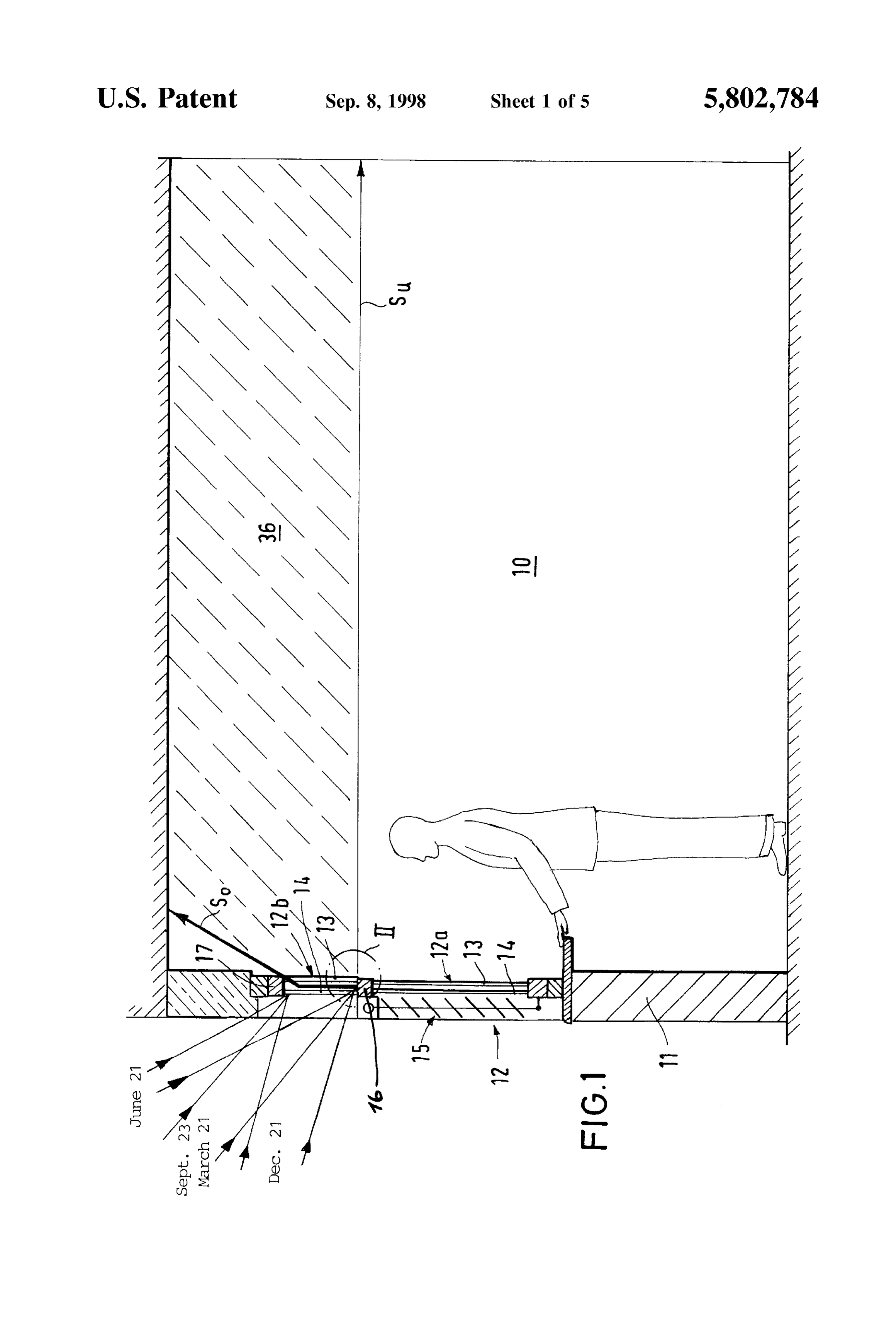
Stacked light-deflecting elements to fit and engage one above another. The light-deflecting elements are thereby adjusted DETAILED DESCRIPTION OF THE automatically to have an optimum aspect to the Sun when a INVENTION Stack is built up, resulting in an accurate construction of the AS seen in FIG. 1, a window 12, which can extend over device, which ensures the optimum light yield. part or over the entire length of a room 10, is disposed in an A Stack comprising a plurality of adjacent light-deflecting exterior wall 11 exposed to Sunlight Such as on the South Side elements, which are preferably adhesively bonded to each of the room 10. The window 12, preferably of hermetically other, can be disposed between two transparent panes of a Sealed insulating window in Such a way that the outlet faces of the light of two transparentglass, has a lower part 12a which consists deflecting elements are oriented towards the location of the from each other. A blind 1513isand panes 14 disposed lateral Spaced disposed on the outside of the room which is to be illuminated. For complete illumination window so that it can be shaded. The blind 15 can be raised of a room, the Stack can be disposed in the upper part or light of a window, the lower light of which is shaded when subject 15 as far as the middle frame bar 16 of the window, if daylight to direct Solar irradiation. For illumination of an individual is to enter also through the lower part 12a of the window 12, Workplace the Stack of light-deflecting elements can be when the Sky is overcast.
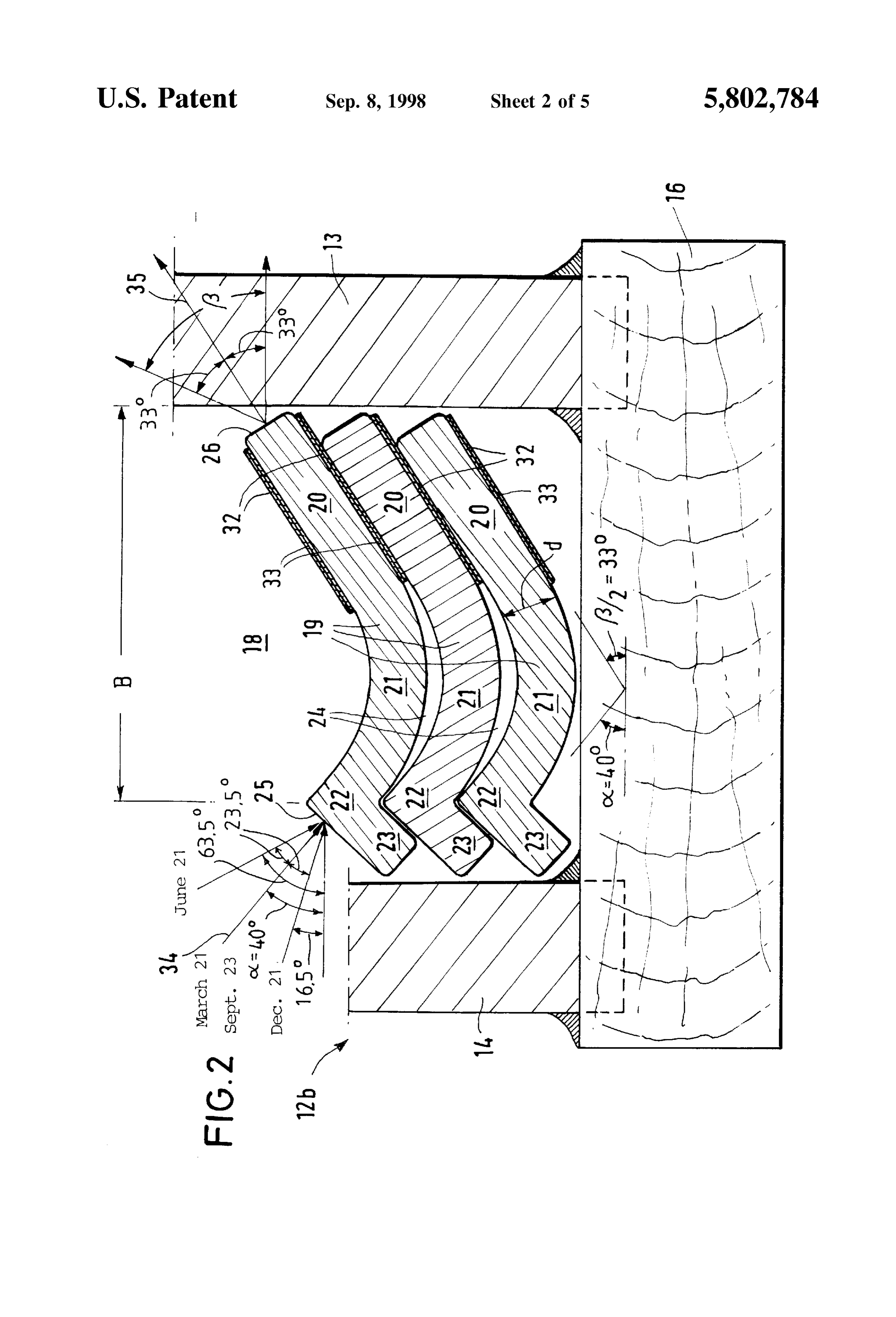
disposed in a high window or ceiling light So that the light The upper part 12b of the window 12 is likewise formed falls downwards onto a workplace. of insulating glazing, comprising an inner pane 13 and an By installing a Stack of light-deflecting elements between outer pane 14, extending between the middle frame bar 16 the panes of a hermetically Sealed window, for example of and the top frame bar 17. In the example illustrated, the a window with insulating glazing, the light-deflecting ele upper panes are at a spacing from each other of about 10 ments are protected from becoming Soiled from UV radia mm, So that an air gap 18 is formed between the two tion and from atmospheric influences; this has a positive transparent panes 13 and 14. A plurality of mutually adjacent effect on the operational reliability and useful life of the 25 light-deflecting elements 19 are stacked one above the other light-deflecting elements. within the air gap 18. The light-deflecting elements extend In order to prevent different levels of brightness at dif over the entire length of the window 12 and in croSS Section ferent locations in the room during the course of a day, have the shape illustrated in FIG. 2.
uniform distribution of the direction of the emerging Solar Each of the light-deflecting elements 19 consists of a rays can be provided at the outlet face by providing light Solid, transparent material; in the embodiment illustrated a Scattering means or material Over the outlet. A profiled transparent Synthetic thermoplastic material in the glassy dispersion lens made of transparent material can also be State is used, polycarbonate (PC), having an optical refrac disposed behind the outlet face of the light-deflecting ele tive index of n =1.586.
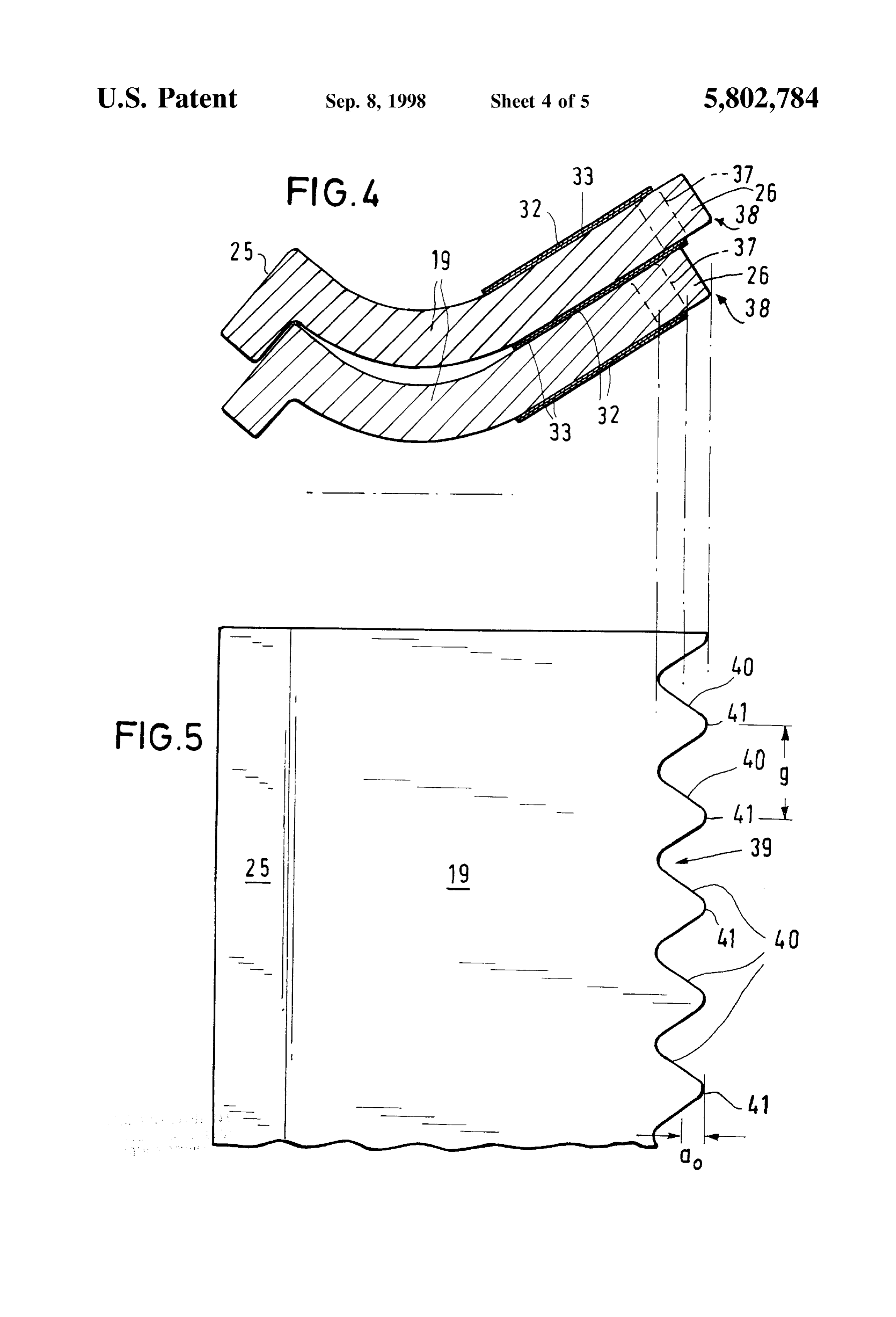
ment in the direction of the rays to effect Such scattering. As can be seen from FIGS. 2 and 3, the light-deflecting It is particularly advantageous to integrally construct the 35 elements 19 are elongated thin plates having a length outlet face with a Sine wave contour, the contour having substantially that of the width of the window and a substan rectilinear, parallel waves on its ray emergence Side, where tially constant thickness d over their entire width B. Each the wavelength g corresponds approximately to 3.64 times light-deflecting element 19 comprises a Substantially recti the amplitude ao and the wave crests run perpendicularly to linear inner end 20, a middle 21, which is curved trans the longitudinal edges of the light-deflecting element. A 40 versely to the longitudinal axis of the light-deflecting construction of the light Scattering means Such as this results element, and an outer end 22. The Outer end 22 has a in a particularly uniform distribution of the light over the projection 23 which extends at right angles to the ends. The entire day. light-deflecting elements 19 rest on top of each other with a Further features and advantages of the invention follow positive fit of their inner ends 20 and engage one above from the description given below and from the drawings, in 45 another with their projections 23. The curvature of the which preferred embodiments of the invention are illustrated Section 21 is more pronounced on its top face than on its by way of examples. bottom face, thus defining a compound curve creating air BRIEF DESCRIPTION OF THE DRAWINGS gaps 24 between the adjacent light-deflecting elements 19, Stacked one on top of another in the region of their mid
In the drawings: 50
Sections 21.
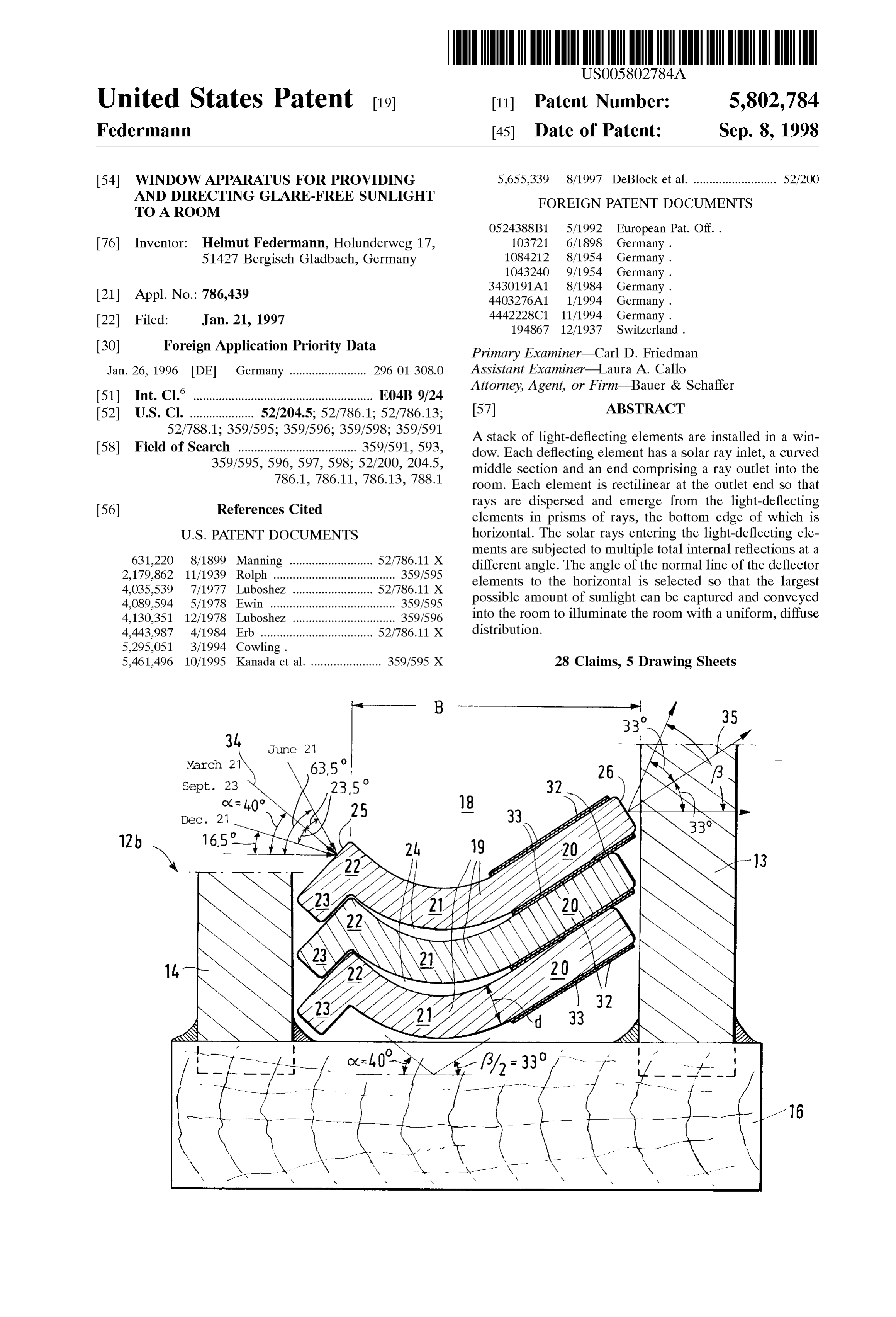
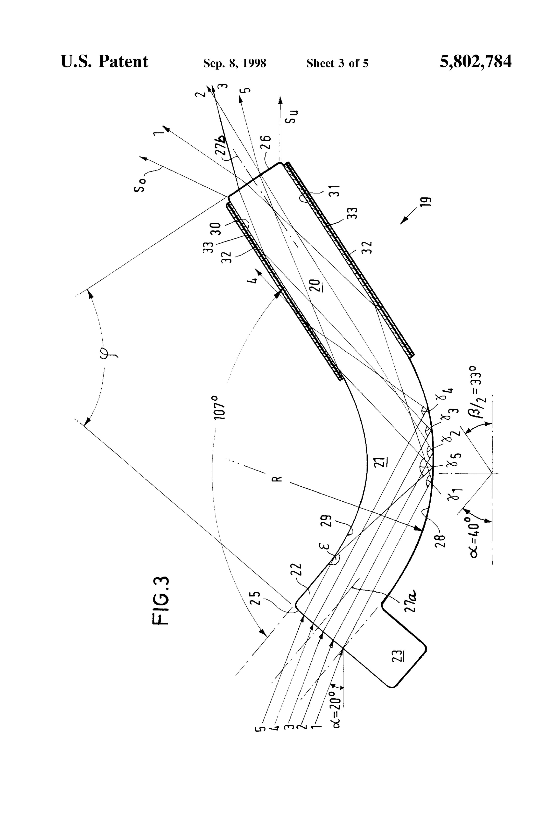
FIG. 1 is a Schematic croSS Sectional illustration of a AS can be seen in more detail from FIG. 3, the outer ends room, which is to be uniformly illuminated with a device 22 form an inlet face 25 for the Solar rays, which are incident according to the present invention; thereon in parallel planes. Only some of the rays 25 are FIG. 2 illustrates the device according to the invention, in illustrated in FIG. 3, being denoted by reference numerals 1, area II of FIG. 1, on a considerably enlarged Scale, 55 2, 3, 4, and 5. The rectilinear inner end 20 forms an outlet FIG. 3 is a vertical cross section through one of the face 26 at its end.
light-deflecting elements illustrated in FIG. 2, in which the The curvature of the mid-section 21 is selected so that the beam path of Solar rays incident at an angle of elevation of central plane 27a perpendicular to the outer inlet face 25 and 20 is illustrated on a scale which is further enlarged the central plane 27b perpendicular to the inner outlet face compared with that of FIG. 2. 60 26 (i.e. also faces 25 and 26) form an angle p with each FIG. 4 is a vertical cross section through two light other, the value of which depends on the latitude of the place deflecting elements of a Stack of Such elements showing of installation. In the example of the embodiment which is light Scattering elements at their outlet faces, illustrated here, this angle p is about 73. FIG. 5 is a partial plan view of the stack of FIG. 4; AS Seen from the example of FIG. 2, it may be assumed FIG. 6 is a partial vertical Section through a room pro 65 that when the beam path of the Solar rays 1, 2, 3, 4, and 5, vided with a roof light or high window, in which a floor area which are incident in parallel planes, impinge on the outer is illuminated by a device according to the invention; and face 25 of the polycarbonate light-deflecting element 19 at

Page 10
an angle of incidence C=20 to the horizontal and travel into at the respective guiding interface 30, 31 which leave the the interior. At the interface 25 between the air and poly outlet face 26 within the cone of light or in a prism of light carbonate material, they are refracted towards the vertical which has an aperture angle of approximate f=66. Accord and impinge, in the region of the mid-Section 21, on the ing to the invention, an aperture angle Such as this can be curved lower face 28, which is also described hereinafter as achieved if the “functional layer” has a refractive index the “guiding interface' of the light-deflecting element. At n=1.491. The “functional layer” at the guiding interfaces 30 this guiding interface between the optically more dense and 31, therefore, cannot be air.
polycarbonate material and the air gap 24, each impinging AS has already been explained above, the Stacked light Solar ray 1, 2, 3, 4 is completely reflected within the element deflecting elements 19 rest with their end parts 20 one on 19 at a different angle, Y, Y-, y-, and Y, since the Solar rays another. They may thus be joined with an adhesive 32 which 1, 2, 3, 4 which enter in Superimposed parallel planes forms the “functional layer”. The adhesive layer 32 is impinge on the guiding interface 28 at different angles at situated between the planar top faces 30 and bottom faces 31 adjacent points. of the end 21. Preferably, an acrylic-based (acrylate) adhe While the solar rays 1 to 4 travel after they enter the Sive bonding agent having an optical refractive indeX deflecting element 19, rectilinearly as far as the lower 15 n=1.491 coated on a sheet-like Supporting means 33 imper peripheral face 28, the Solar rays 5 which are incident in the vious to light Such as a thin, black film of Synthetic material uppermost plane first impinge on the upper curved face 29 is used. This black film of synthetic material forms an after they enter the light-deflecting element 19. These upper absorption layer in which the light rays which are decoupled rays 5 are reflected at an angle e and are directed down from the inner end part 20 at the guiding interfaces 30 and wardly towards the opposite, lower face 28, where they too 31 thereof are absorbed so that they will not stray and will are also totally reflected internally at an angle of Ys. not enter adjacent light-deflecting elements. It is preferable that the radius of curvature R of the lower It can be seen that for the light rays 1, 2, 3, and 5, which guiding interface 28, at which the Solar rays are reflected in are reflected at the guiding interfaces 30 and 31 and which the interior of the light-deflecting element be as large as reach the outlet face 26, a numerical aperture NA=Sin B/2 possible. In the present case, the mid-Section 21 is curved in 25 gives the form of a circular arc and adjoins the end parts 20 and 22 tangentially. The mid-Section may also be curved in the NA= nt. n : 0.54, form of another form of curve.
As can be seen from FIG. 3, the rays 1, 2, 3, 4 and 5, which are reflected from the guiding interface 28 are trans which corresponds to an aperture angle of Bs2.33 =66. mitted into the rectilinear inner end part 20, where they In order to ensure that Solar rays only reach the top third impinge on its planar top face 30 or its planar bottom face of the room 10, as illustrated in FIG. 1, the lowermost Solar 31, which are likewise "guiding interfaces”. In contrast to rays S. emerging from the outlet face 26 must be caused to the mid-section, in which all the Solar rays 1 to 5 are travel horizontally. Thus, the uppermost rays So of the prism reflected and are thereby deflected and transmitted, in the 35 of rays emerging from the outlet face 26 of the uppermost region of the rectilinear inner end part 20, only those rays 1, light-deflecting elements 19 in the stack will reach the 2, 3 and 5 are reflected and transmitted which impinge on the ceiling of the room at an angle of 66 to the horizontal So that guiding interfaces 30 and 31 at an angle which is greater almost the entire ceiling area of the room 10 is irradiated. than the critical angle for total internal reflection. RayS AS Seen in FIG. 2, the angle C. made between the perpen which impinge on the planar guiding interfaces 30 and 31 at 40 dicular line 34 on the admission face 25 and the horizontal a lesser angle, Such as the ray 4, are not reflected but emerge is determined for the respective place of installation accord laterally from the light-deflecting element and are lost. ing to the highest Solar altitude in the middle of the year, According to the present invention, it is intended that the namely according to the highest angle of elevation of the Sun incident Solar rays are to be directed into quite a defined part on March 21 or September 23, which at 50° latitude (e.g. in of the room 10. For example, with the embodiment illus 45 the city of Mainz, Germany) amounts to 40. On June 21 this trated in FIG. 1 the rays are to be deflected only into the top highest angle of elevation of the Sun is 23.5 higher, and on third of the room So that perSons working in the room cannot December 21 it is 23.5° lower. It follows from this that the be dazzled with light. Furthermore, as much light as possible highest Solar altitudes vary within an angular range of 47 is to enter this top third of the room to be diffusely reflected over the year, and within the course of the day, Starting in the from the ceiling and from the Surrounding walls of the room 50 morning, the Solar altitude at 50 latitude can reach an angle into the bottom part of the room. Consequently, the Solar of elevation of 63.5 to the horizontal at midday. Since the rays have to emerge from the outlet face of the elements 19 Sunlight at 50 of latitude has its highest luminous intensities in a conical array which is as large as possible. An angle of which can be used for indirect room lighting within the emergence B of 90 would be ideal but this can only be vertical angular range between 16.5 and 63.5 over the achieved with high loSS of light at the planar guiding 55 course of the year, the outer end part 22 of the light interfaces 30 and 31. If loss of light is to be substantially deflecting element 19 is disposed at an angle of 40 to the prevented and if the lowermost Solar raySS, of the prism of horizontal, which bisects the entire range of the angle of rays are to emerge and travel horizontally in the room, the elevation.
rectilinear end 20 of the light-deflecting element 19 should This angle, of course, has to be different at other places of be inclined at an angle B/2 to the horizontal So that the 60 installation if the maximum incidence of light there is to be aperture angle B falls between 60 and 72. In order to utilized over the year.
produce an aperture Such as this, it is necessary to provide It can be seen that with the construction and arrangement the guiding interfaces 30 and 31 of the rectilinear inner end of the light-deflecting elements 19 which has been described part 20 of the light-deflecting element 19 with a “functional it is possible to capture the largest possible amount of light layer', the refractive index n of which is matched to the 65 throughout the whole year, to Scatter the Solar rays which are refractive index n of the material of the light-deflecting incident in parallel on the outer end 22 by multiple total element 19 in such a way that only those rays are reflected internal reflections in the curved mid-section 21 and the
Page 11
rectilinear end 20 and to conduct this light in scattered form are possible without departing from the Scope of the inven but in a uniform distribution to a defined location 36 in a tion. For example, it is also possible for light-deflecting room 10 and thereby to fill the entire room with glare-free, elements according to the present invention to be fixedly diffused light. It can also be seen that the light-deflecting installed in a wall if no special windows are provided. elements 19 can easily be manufactured individually and can Moreover, the light-deflecting elements according to the be reliably Stacked one above another and can be accom invention can be installed not only in flat roofs but also in modated adhesively bonded in the air space 18 of a insu double-ridged roofs, and it is also possible for the light lating double-pane glass window where they are removed deflecting elements to be fashioned differently. For example, from environmental effects and from contamination So that providing a different curvature to the middle Section and their efficacy is not impaired even after extended periods of varying the angle between the admission face and the outlet face is possible in order to adapt the light-deflecting ele
In order to also achieve uniform illumination of the room ments to the respective place of installation, i.e. of the respective latitude and the path of the Sun thereof. Finally, 10 over the course of a day and to take into account the other Solid transparent materials can be used Such as glass or migration of the Sun in a horizontal direction from east via Synthetic materials similar to glass together with functional South to West, auxiliary light Scattering means 37 Such as 15 layers which are suitable therefor, provided that their refrac shown in FIGS. 4-5 may be provided. With the auxiliary tive indices can advantageously be matched to each other. means 37, the Solar rays which are incident in different In order to increase the light yield, it is also possible to directions over the course of a day can be distributed more provide at least the rectilinear inner end parts 20 of the uniformly at the outlet face 26 of the light-deflecting ele light-deflecting elements 19 with a reflection layer at their ments 19. This auxiliary light scattering means 37 horizon planar bottom faces, for example with a film of Synthetic tally fans out those Solar rays which are incident in parallel material which is vacuum-metallized on its outer face and and deflects them towards the middle of the room. The only to provide an absorption layer at the planar top face of auxiliary means 37 illustrated in FIGS. 4 and 5 is formed as the inner end part 20. It is thereby ensured that no light rays an integral part of the outlet face 26 itself, wherein the inner can emerge at the lower guiding interface in any event but longitudinal edge 38 of the light-deflecting elements 19 is 25 that rays which also impinge thereon at a Steeper angle are constructed with a sine wave surface 39 which has reflected towards the upper guiding interface. rectilinear, parallel waves 40, the wave crests 41 of which herein, Various modifications and changes have been disclosed run perpendicularly to the longitudinal edges 38 of the and others will be apparent to those skilled in this art. light-deflecting element 19. The wavelength g of the sine Therefore, it is to be understood that the present disclosure wave approximately corresponds to 3.64 times the ampli invention. of illustrating and not limiting of the present is by way tude ao. The Solar rays which are incident obliquely in the What is claimed is:
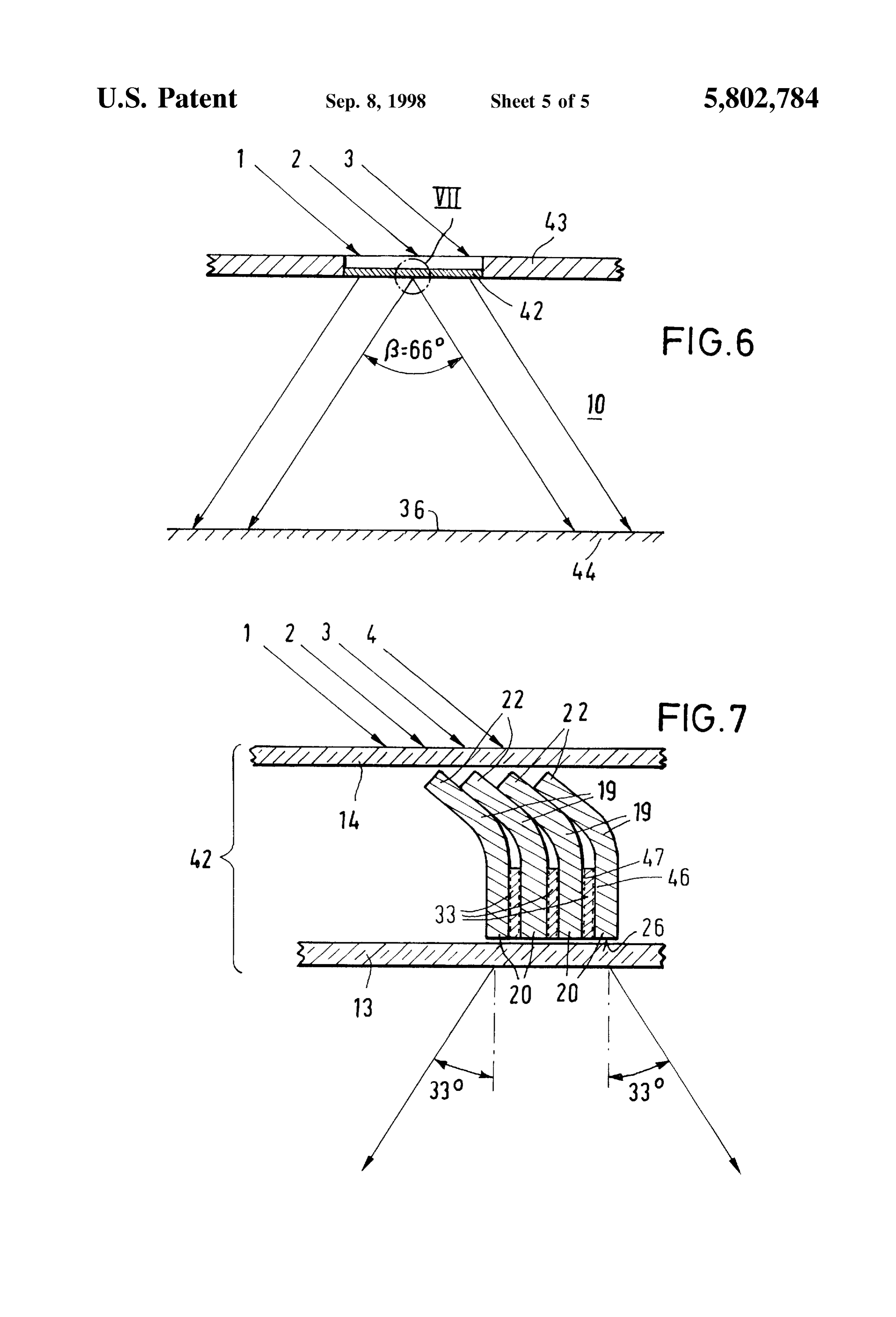
morning and afternoon are deflected towards the middle of 1. A window apparatus for providing glare-free diffused the room by a wave-like profile 39 of the outlet faces 26. Sunlight to a room, said apparatus comprising at least one This results in uniform illumination of the room 10 over the light-deflecting element having an inlet face adapted to be entire length thereof. 35 exposable to the Sun's rays, an outlet face adapted to be The same effect can also be achieved if a profiled disper exposable to the room to be lit and an intermediate Section Sion lens made of transparent material is disposed behind the for guiding and dispersing the Sun's rays to and through Said outlet face 26 of the light-deflecting element 19 in the outlet face toward a Selected location in the room, the Said direction of the rayS. However, an embodiment Such as this inlet face and Said outlet face being disposed at an angle to is not illustrated in the drawings. 40 each other and the intermediate Section being curved and FIGS. 6 and 7 illustrate another embodiment of the being formed rectilinearly at least at its end adjoining the invention, in which the light-deflecting elements 19 are outlet face to have mutually opposing peripheral faces disposed between two glass panes 13 and 14 in a Skylight 42. forming a guide path for Said rayS.
These elements direct the Solar rayS 1, 2, 3 falling on a flat 2. The apparatus according to claim 1, wherein the end of roof 43 onto a location on the floor 44, i.e. of a factory bay 45 Said light deflecting element is coated with a functional layer 45 in order to obtain uniform illumination there over the of light refractive material having a refractive index matched entire day. to the refractive index of Said light deflecting element So that In this embodiment, the inner ends 20 of the light only those rays which are internally reflected within said end deflecting elements 19 are disposed with their outlet faces 26 leave the outlet face shaped within an aperture angle directly above the inner glass pane 13 of the Skylight 42, and 50 between 60 to 72.
the elongated outer ends 22, which are also rectilinear, are 3. The apparatus according to claim 2, wherein the shape adjacent to each other. In this embodiment, the inner end of the rays leaving the outlet face are prismatic. parts 20 are at a Somewhat greater spacing from each other, 4. The apparatus according to claim 2, wherein the and it is necessary to provide light-absorbing, sheet-like Shaping of the rays leaving the outlet face is conical. Supporting plates 33 between them. These Supporting plates 55 5. The apparatus according to claim 2, including a layer bear an adhesive 32 forming the “functional layer” on their of light absorbing material disposed on the Surface of Said mutually opposite faces 46 and 47 So that the adjacent light refractive layer.
elements 19 can be joined by their end parts 20. Solar rays 6. The apparatus according to claim 5, wherein Said light which impinge on the guiding interfaces at an angle which absorbing material is applied in a layer to be impervious to is less than the critical angle for total internal reflection are 60 light.
deflected into the absorption plates 33 as described in detail 7. The apparatus according to claim 5, wherein Said light earlier and are absorbed there, whilst the multiple-reflected absorbing material in a layer to light attenuating. light rays emerging from the outlet face 26 are directed onto 8. The apparatus according to claim 5, wherein Said light the floor 36 of the factory bay in a cone of light with an absorbing material layer comprises a color filter. aperture angle of 66. 65 9. The apparatus according to claim 1, including a plu The invention is not restricted to the examples illustrated rality of light-deflecting elements fixedly Stacked one upon and described. Rather, numerous modification and additions the other.
Page 12
10. The apparatus according to claim 9, wherein a trans 22. The apparatus according to claim 19, wherein the light parent film is interposed between each of the Stacked light Scattering and distribution means has a Sine wave face with deflecting elements, Said film having adhesive on each rectilinear, parallel waves emerging from the outlet face, the Surface to fixedly Support Said deflecting elements. wavelength of Said Same wave being approximately 3.64 11. The apparatus according to claim 10, wherein Said film times the amplitude and the wave crests, Said Sine wave is made of reflective material. running perpendicularly to the longitudinal edges of the 12. The apparatus according to claim 10, wherein the end light-deflecting element.
of the light-deflecting element has a planar bottom face and 23. The apparatus according to claim 9, wherein the light a planar top face and the planar bottom face is provided with deflecting elements are formed So that the intermediate a reflective layer and the planar top face is provided with a Sections of adjacently Stacked deflecting elements are sepa light absorbing layer. rated from each other by an air gap therebetween. 13. The apparatus according to claim 12, wherein the 24. The apparatus according to claim 23, wherein the ends absorbing layer is a sheet Supporting means which is imper of the light deflecting elements include projections extend vious to light, Said Supporting means bears adhesive on each ing at right angles to the light deflecting elements So that Surface by which adjacent light-deflecting elements in Said 15 adjacent light-deflecting elements engage one another in Stack are joined to each other. Said Stack.
14. The apparatus according to claim 12, wherein the 25. The apparatus according to claim 24, wherein the reflective layer is a transparent film of Synthetic material projections extending at the inlet face of each of Said which is vacuum-coated with aluminum on the Surface of deflecting elements are planar. the film remote from the light-deflecting element. 26. The apparatus according to claim 9, wherein the 15. The apparatus according to claim 12, wherein the light-deflecting elements are joined by means of an light-deflecting element consists of a Synthetic thermoplastic adhesive, the adhesive being a layer of light-refractive material in a glassy State. material.
16. The apparatus according to claim 15, wherein the 27. The apparatus according to claim 1, wherein the light-deflecting element consists of polycarbonate. 25 light-deflecting element is an elongated thin plate of Sub 17. The apparatus according to claim 15, wherein the Stantially uniform thickneSS having a longitudinal edge adhesive is an acrylic based (acrylate) adhesive bonding forming the inlet face and another planar longitudinal edge agent. forming the outlet face, the intermediate Section being 18. The apparatus according to claim 12, wherein Said curved transversely to the longitudinal axis of the light deflecting elements are disposed within a pair of hermeti deflecting element.
cally Sealed parallel window panes. 28. The apparatus according to claim 27, when installed 19. The apparatus according to claim 12, wherein the in the wall of a building is arranged So that the inlet face of outlet face is provided with means for Scattering the light the light-deflecting element forms an angle with the and uniformly distributing the light over the course of the horizontal, Said angle being calculated as the maximum day. 35 angle of elevation of the Sun at the annual average Solar 20. The apparatus according to claim 19, wherein said altitude at the site where the building is placed, and that the Scattering and distributing means is integrally formed with outlet face of the light-deflecting element forms an angle Said outlet face. with the horizontal calculated to correspond to the maximum 21. The apparatus according to claim 19, wherein Said half angle of the light rays emerging from the outlet face. Scattering and distributing means comprises a profiled dis 40 persion lens. k k k k k
Provenance
- Collection
- Cited prior art
- Original PDF
- patentimages.storage.googleapis.com →
- Filed
- 1997-01-21
- Pages
- 12
- Method
- pdftotext (the PDF's own text layer) + pdftoppm 300dpi page scans
- Source
- Google Patents bibliographic record
- Granted
- 1998-09-08
- Inventors
- Helmut Federmann
- Transcribed from
- patentimages.storage.googleapis.com →