patent · US1696003
Solar-heat-accumulating system
18 December 1928
Page 1
Drawing sheet — no readable text.
Page 2
Drawing sheet — no readable text.
Page 3
Patented Dec. 18, 1928. 1,696,003
UNITED STATES PATENT OFFICE.
wALTER. J. HARVEY, oF ToRoNTo, ONTARIo, CANADA.
soLAR-HEAT-ACCUMIULATING sYSTEM.
Application filed October 21, 1924. Serial No. 744,997.
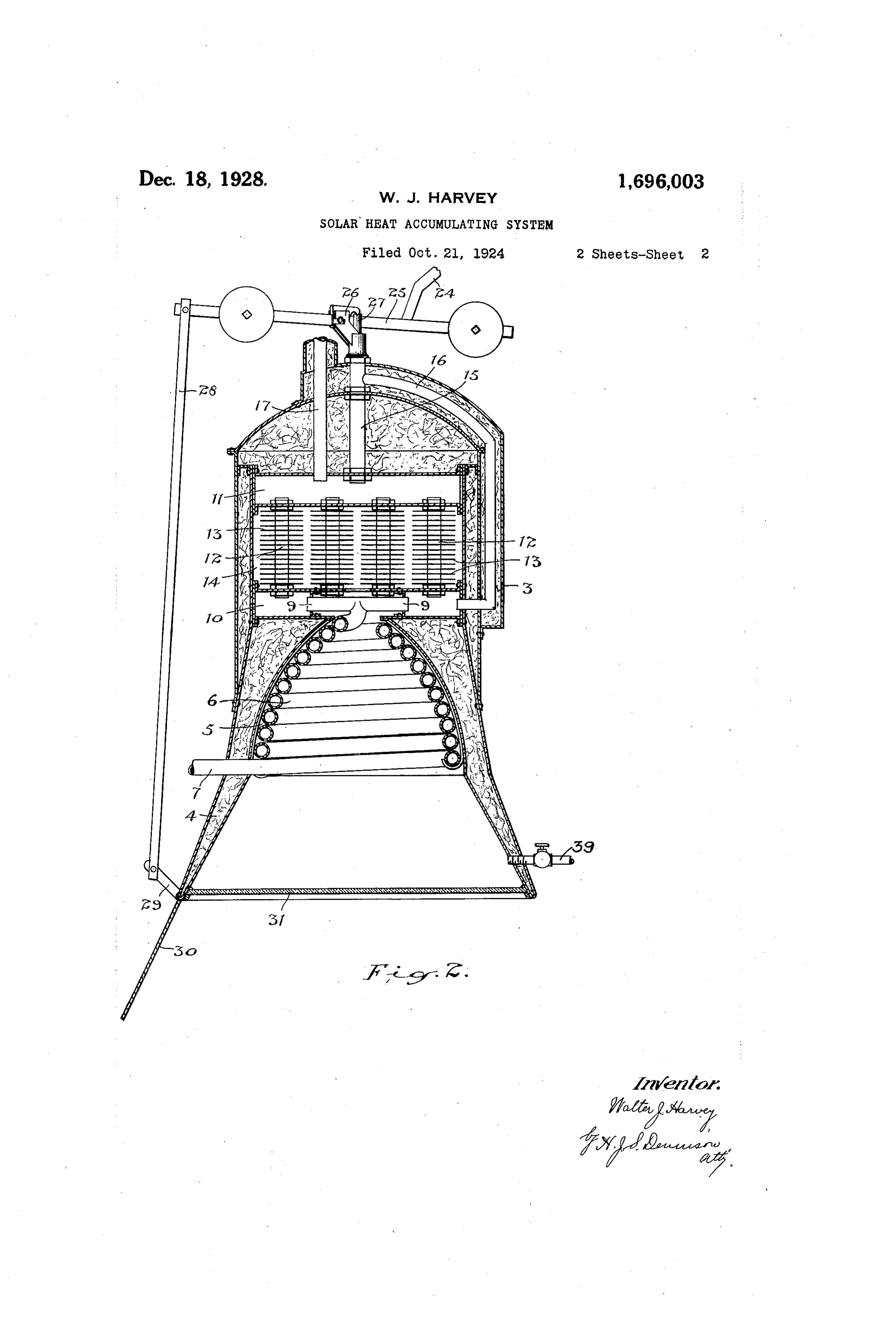
The principal objects of this invention are, connected this chamber with an annular chamber 10 and is connected with a chamber to accumulate and store the heat of the Sun's rays for commercial heating purposes, and 11 arranged thereabove by a plurality of to devise a simple and economical form of tubes 12.
The tubes 12 are shown provided with a automatic device for accomplishing the de plurality of heat absorbing discs 13 within sired object. the chamber 14 enclosing the tubes and the The principal features of the invention consist in the novel arrangement of means heat reflected into the transmitting device after heating the coil 6 is further absorbed for concentrating the Sun's rays with a
O means for transferring the heat energy of by the discs 13 and the tubes 12. the rays to a circulating storage fluid. A tube 15 leads upwardly from the top of In the accompanying drawings, Figure 1 the A chamber 11 and contains a thermostat.
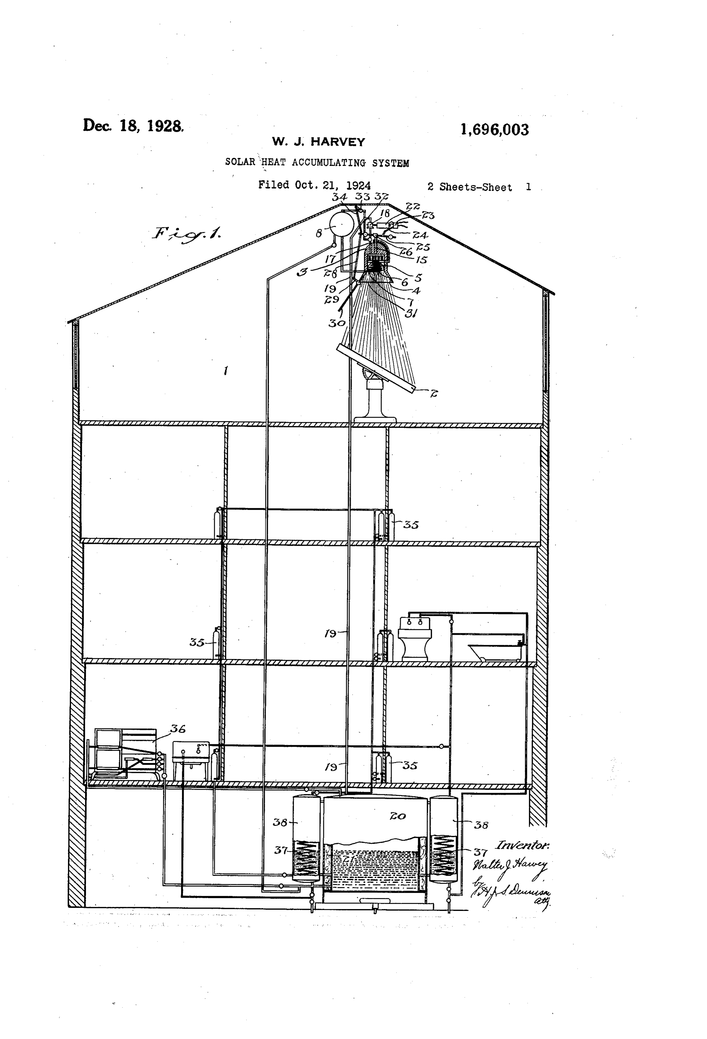
circulating tube 16 leads from the top of is a vertical sectional diagram of a heatin the tube 15 back to the chamber 10 sothat installation for a house.
5 Figure 2 is an enlarged vertical sectional there will be a constant circulation of the fluid medium for transmitting the heat view through the concentrating heater.
The active heat of the Sun's rays is of through the tube 15 carrying the thermostat. i course a well known fact and many devices chamber 11 andtube
Anoutflow 17 leads from the upper i have been conceived for concentrating the pump 18 whichis connected forces the to a circulating 75 heated fluid 20 rays so that the heat may be utilized for in stance, by the direct application of the rays medium through a conduit 19to a storage re ceiver 20 which is here shown arranged in toheating a boiler.
The present invention contemplates the the basement of the building and which is enclosed within an insulating casing 21.
utilization of the heat of the rays to heat a The pump 18 is of any suitable design op 80 25 medium which will retaina high temperature for a considerable period of time and which cated erated by any suitable form of motor indi will dispense the accumulated heat as may be motor in Figure 1 by the numeral 22. This canbe controlled byany desirable form desired for various purposes.
In the method of utilizing the Sun's heat of switch mechanism and the switch 23, the 30 illustrated herein, the diagram shown in Fig details of which are not shown, is connected ure 1 illustrates a house equipment. On the bar with an arm 24 extending from the pivoted upper floor of the house is arranged a room 1 the top 25 carried on the bracket 26 mounted on which is open to receive the rays of the sun is actuated of the transmitting device and which through glazed walls and roof and within The bar 25 by has the thermostat connected rodits27.outer end 90
this room is arranged a suitable form of re rod 28, the lower end of the rod being con flecting device 2 whichisso constructed as to anected to the arm 29 of the shutter 30, which reflect the Sun's rays to a fixed point through is pivotally out the day. The construction of this re the apron 4. supported at the lower rim of i flecting device is notherein shown as differ The apron 4 is preferably provided with a 40 ent forms may be devised and such construc shield 31 of quartz through which the re tion does not form part of the present in flected rays from the reflector 2 are directed vention.
Arranged above the reflecting device 2 is and the shutter is adapted to close over the quartz plate in the event of the heat becom the heatreceiving and transmitting device ing too intense.
45 3, which is here shown in the form of a hood having its walls formed of heat insulating theWhen bar the thermostat rod expands it tilts 25 on its pivot and through the rod or refractory material. This hood is formed with a circular converging apron 4 leadingto 28Aitsbranch swings the shutter. a chamber 5 of concave form. Opening flow pipe 17 pipe and 32 is connected to the out 105 leads to the top tank 8 and 50 downwardly and within the chamber 5 is ar is provided with ranged a tubular spiral coil 6 havingits in is connected by a link 34 witha valve 33. The valve 33 let end 7at the bottom connected with a tank the bar 25 and 8 arranged above the device 3. is so adjusted that when the thermostat ex The upper end of the coil 6 is preferably p ands to a predetermined point it will open 0 branched with laterally arranged leads 9 the valve 33 and allow the flow of the fluid
Page 4
medium to the tank 8 and thus provide a which means ràay be in the form of an oil local relief.
Oil of a high flash point is the preferred burner,
The a gasburner oran electric heater.
equipment shown is of course merely 45 fluid medium for receiving and storing the 5 heaù and as the Sun's raysare reflected from diagrammatic and the construction of the ap paratus is also largely diagrammaticas it the surface of the reflector 2 into the con may be altered in detailsto a considerable ex cave chamber 5 they are absorbed by the coil tent without departing from the spirit of the 6 and the oil contained therein flows up invention. 50 wardlyinto the chamber 10 through the tubes VVhat I claimas my invention is:- 0 12 into the chamber 14 and from thence 1. In a solar heat accumulating system, a through the outflow tube 17 from which it is diurnal reflector adapted to direct the Sun's pumped to the storage receiver 20. rays to a fixed point, a receiver adapted to A temperature in the neighborhood of 700° contain
Fmay be attained by the oil but in the eventi culatingaconduit fluidheat absorbing medium, a cir -55 of the heat being so intense as to raise the a helically shapedconnected with said receiver, temperature of the oil in the heater coil above said conduit and arranged atcoilsaid tubular introduced in fixed point, a predetermined point the shutter 30 is oper a chamber connected with the upper ated by the thermostatto deflect the rays from said coil, tubes leading upwardly fromendsaid of the reflector and also to open the local relief chamber, an annular chamber connected with 60 20 through the branch pipe 32.
In the diagram illustrated in Figure 1, from the upper ends of said tubes, a pipe leading various pipesare connected to the receiver of thethe upper chamber and forming part circulating conduit, a pump arranged 20 and oil may be taken therefrom at high in said upper pipe, and means for operating 65 temperature to the variousheating appliances said pump to effect the circulation of said throughout the house, such as the radiators heat absorbing fluid.
35 or the stove 36. 2. In a solarheat accumulating system, an The return circulation carries the oil back insulated receiver adapted to contain a fluid to the receiver at a lowpoint. heat absorbing medium, a circulating conduit VVater heaters 37 are shown in the form of connected with said receiver, a heat exchange 70 i 30 coils passing through tanks 38through which device connected with said circulating con the hot oil is circulated and the water from duit, a diurnal reflector adapted to concen these coils is carried to the various heating trate the sum's rayson said heat exchange de appliances throughout the building. vice, a shutter adapted to be interposed be 75 It may be found desirable to exhaust the tween the reflector and saidheat exchange de air from the chamber 5 and a pipe 39 is pro vice for controlling the reflectedrays, a ther vided for this purpose. . . mostat arranged in said heat exchange de In the use of this device the storage me vice, means operatively connecting saidther dium will retain a high temperature for a mostat with said shutter for operating the 80
considerable period but in the event of pro latter, and means for circulating the fluid tracted dull weather when the Sun's rays are medium through said conduit and receiver. obscured a supplementary heating means is provided beneath the storage receiver 20 WALTER J. HARVEY.
Provenance
- Collection
- Cited prior art
- Original PDF
- patentimages.storage.googleapis.com →
- Filed
- 1924-10-21
- Pages
- 4
- Method
- pdftotext (the PDF's own text layer) + pdftoppm 300dpi page scans
- Source
- Google Patents bibliographic record
- Granted
- 1928-12-18
- Inventors
- Walter J Harvey
- Transcribed from
- patentimages.storage.googleapis.com →