patent · US4434785
Heat accumulator
6 March 1984
Page 1 — bibliographic record
United States Patent (19) (11) 4,434,785 Knudsen 45) Mar. 6, 1984 54) HEAT ACCUMULATOR 4,267,881 5/1981 Byerly ................................. 126/436 4,286,651 9/1981 Steiger .................................. 165/45 76 Inventor: Niels K. Knudsen, Rolighedsvej 13, 4,301,965. 1 1/1981 Ritter .................................. 126/427 DK-8722 Hedensted, Denmark FOREIGN PATENT DOCUMENTS 21 Appl. No.: 431,725 3018337 11/1980 Fed. Rep. of Germany ........ 165/45 22 Filed: Sep. 27, 1982 2419470 1 1/1979 France .................................. 165/45 2470938 6/1981 France ...... 165/45
Related U.S. Application Data 2495741 6/1982 France .............. ... 65/45
doned. Primary Examiner-Samuel Scott
Assistant Examiner-G. Anderson (30) Foreign Application Priority Data Attorney, Agent, or Firm-Lewis H. Eslinger Sep. 6, 1979 (DK) Denmark ............................. 3720/79 57 ABSTRACT 51) Int. Cl.......................... F24H 7/00; F28D 00/00 An underground heat accumulator of the low tempera 52 U.S. C. ...................................... 126/400; 165/45; ture type for storing solar energy from a solar collector
58) Field of Search ............... 126/400, 430, 435, 436; (8) by means of a plurality of buried double pipes with 165/45, 18 an outer pipe (3) and an inner pipe (5) has said pipes conically disposed, extending from a central well (1) (56) References Cited with a cover (2) near the surface of the ground.
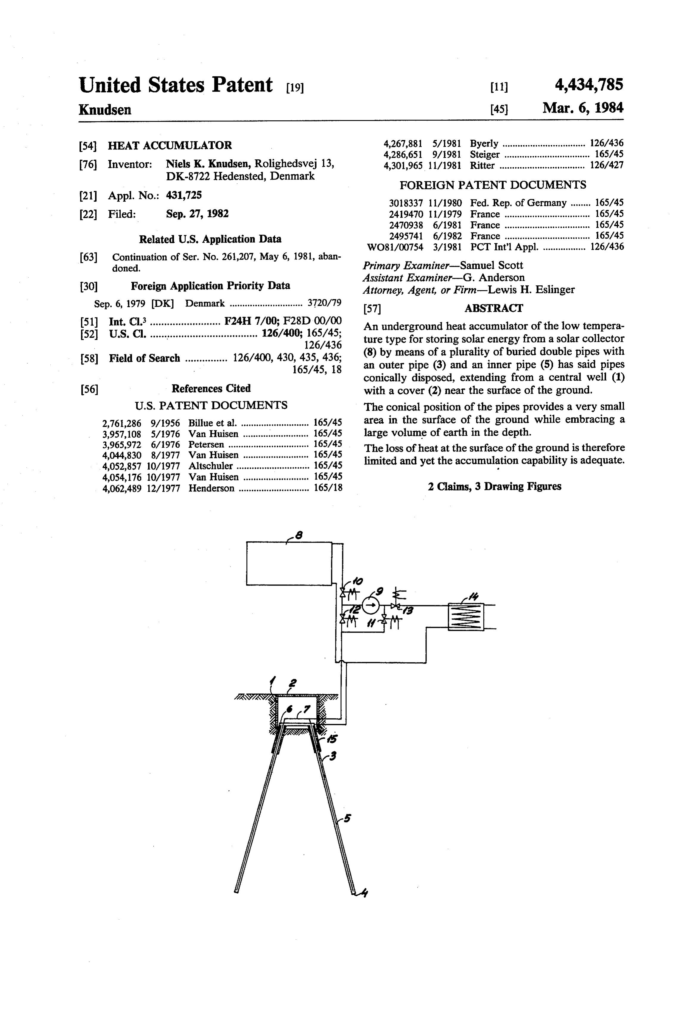
2,761,286 9/1956 Billue et al. ........................... 165/45 area in the surface of the ground while embracing a 3,957,108 5/1976 Van Huisen . ... 165/45 large volume of earth in the depth.
3,965,972 6/1976 Petersen ........... ... 165/45 The loss of heat at the surface of the ground is therefore 4,044,830 8/1977 Van Huisen .......................... 165/45 limited and yet the accumulation capability is adequate. 4,052,857 10/1977 Altschuler ............................. 165/45 4,054,176 10/1977 Van Huisen .......................... 165/45 4,062,489 12/1977 Henderson ............................ 165/18 2 Claims, 3 Drawing Figures
Page 2
Drawing sheet — no readable text.
Page 3
Drawing sheet — no readable text.
Page 4
surface of the ground and consequent disturbance of
HEAT ACCUMULATOR nature's own temperature.
According to the invention the capacity of the heat
This is a continuation of application Ser. No. accumulator may advantageously be dimensioned by 06/261,207, filed May 6, 1981 now abandoned. 5 adapting the physical size of the accumulator so as to The invention relates to an underground heat accu provide equilibrium, on an annual basis, between the mulator of the low temperature type, with buried verti accumulation capability and consumption of heat by cally disposed double pipes for storing solar energy for determination of the number and length of the double residential heating. pipes from one or more central wells. Accumulators for storing solar energy have either an 10 The original temperature of the earth provides an insulated water tank or direct accumulation in the additional energy store which can be used following a ground about buried pipes which may be covered by a period of few sunny days. In the following year the heat insulating material at the surface of the ground. In efficiency of the solar collector will increase because of systems where solar energy is stored in an underground the lower flow temperature from the accumulator. heat accumulator of the low temperature type with 15 The desired consumption of heat and the required vertically disposed double pipes, the solar energy is fed solar collector area adapted to the accumulator in such from the solar collector to the bottom of the outer pipe a manner that the temperature of the double pipes at the through the inner pipe, and the heat stored in the heat top near the bottom of the central well does not differ accumulator is given off from the bottom of the outer much from the original temperature of the earth in long pipe through the inner pipe to the heat system through 20 periods, but only at the end of the accumulation period the evaporator of a heat pump. The pipes may be in in the autumn may occur a slight increase in tempera clined from a circular area of larger diameter than the ture. During subsequent consumption the top of the storage area and be covered by an insulating layer double pipes rapidly gives off its heat to thereby shorten which also insulates the connections to the pipes. the period of increase in temperature. The duration of Such methods require much and expensive digging in 25 the period is the time to be used when determining the order for pipes and insulation or other defining coating length of the heat insulating jacket from the bottom of to be fitted, and the costs involved prevent solar energy the central well.
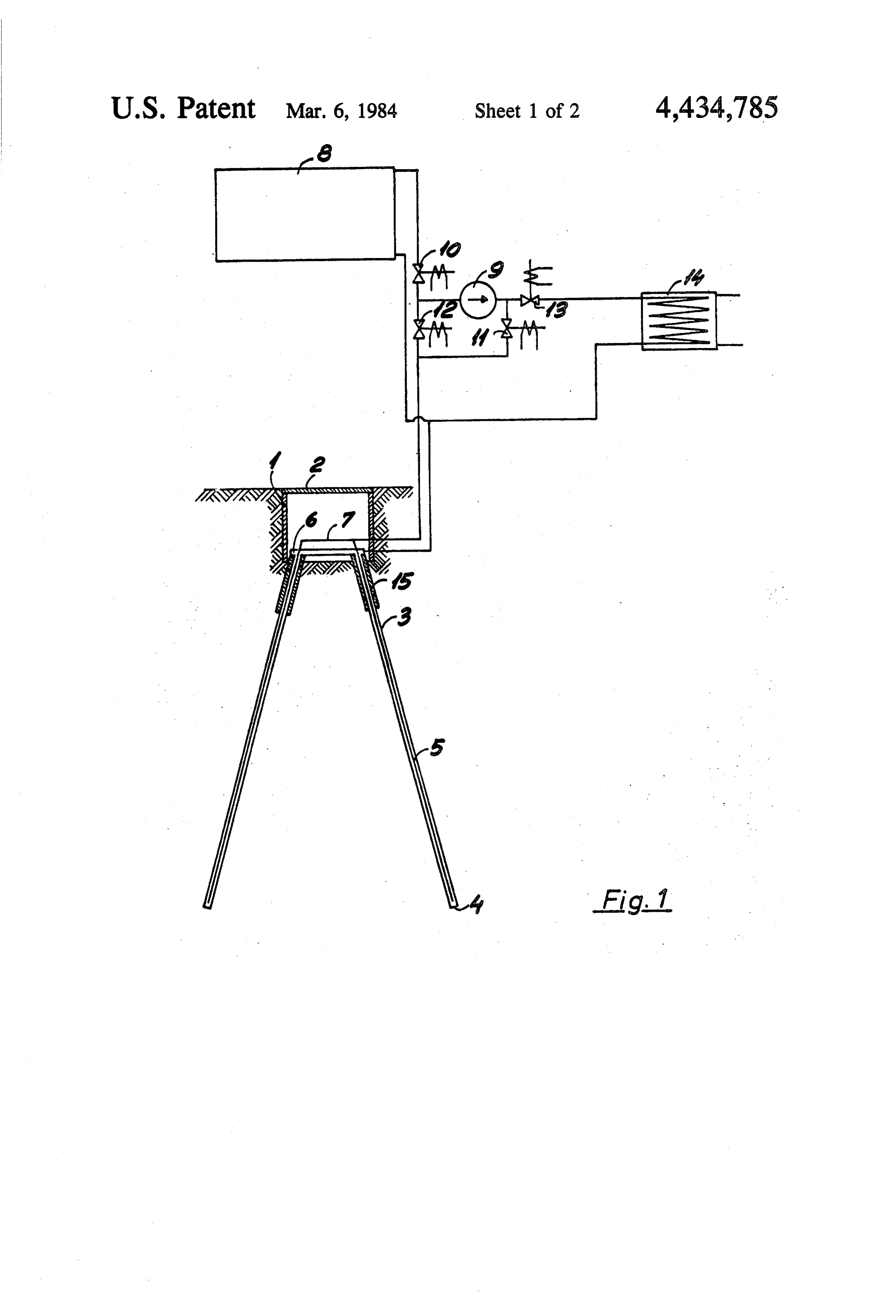
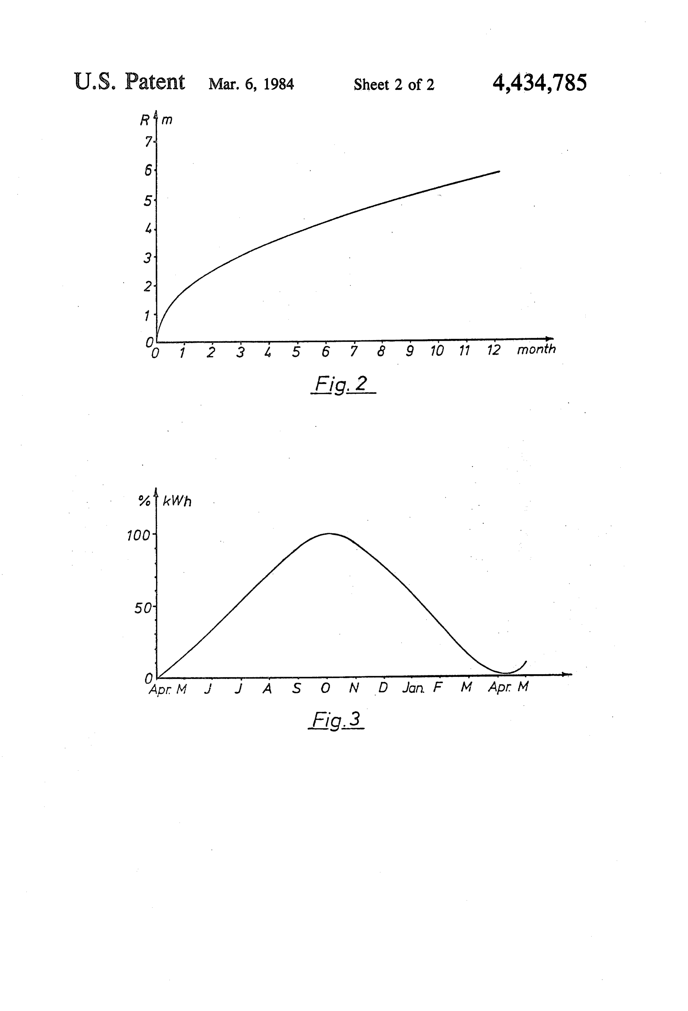
from being used for ordinary residential heating. The A heat accumulator of the invention is shown in the accumulation capability and efficiency often turn out to drawing in which be much too poor at increasing temperatures in accumu 30 FIG. 1 is a diagrammatic, vertical section of the accu lators having a too limited accumulation volume so that mulator with associated pipe connections in diagram, an increase in the mean temperature of the solar collec FIG. 2 shows a curve illustrating the diffusion of the tor results in a significantly poorer capture of heat. accumulated heat in the ground, and Therefore the area of the solar collector must be very FIG.3 shows a curve for a period from April to April large and correspondingly expensive. 35 with accumulation and subsequent consumption in per The heat accumulator of the invention is character cent kWh of the heat requirement. ized in that the pipes are vertically, conically inclined The heat accumulator comprises a central well 1 with with a common geometric vertex near the surface of the a cover 2 at the surface of the ground. From the bottom ground. of the central well are dug an outer pipe 3 with a bottom The very small area near the surface of the ground 4, and an inner pipe 5 extending down to the bottom 4 minimizes the loss of heat, and at the same time the of the outer pipe 3. For sufficient energy to be stored, inclined position of the pipes embraces a very large several such double pipes must be fitted which are con quantity of earth as accumulation volume. nected in parallel from a distribution pipe 6 to the outer The conical mounting of the pipes allows rational pipes 3 and another connection pipe 7 to the inner pipe operation when installing the accumulator and provides 45 5. The distribution pipes 6 and 7 are connected to a solar a very great accumulation capability, optimizing the collector 8 from which heat is transported by an anti efficiency of the solar collector and the associated heat freeze liquid by means of a pump 9 having a valve 10 pump. Consequently, it is therefore economically and and 11 opened for flow to the pipe 7 which carries heat technically possible to use solar energy in practice for to the inner pipes 5 and the bottom 4 of the outer pipes ordinary residential heating. 50 3. On its way up through the pipes 3 heat is given off to The central well of the heat accumulator may be the surrounding earth which according to calculations reduced according to the invention because the upper can store a considerable amount of heat which is very portion of the outer pipe below the surface of the slowly passed out to the circumjacent earth, for which ground is formed with a tubular heat insulating jacket at reason the loss of heat to the surroundings is of mini the bottom of the central well. 55 mum importance.
Calculations show a correlation between diffusion of When heat is received from the accumulator the heat in the ground and the time spent, whereas the valves 10 and 11 are closed, while a valve 12 and 13 temperature does not affect the extent of diffusion but opens and the pump 9 passes the heat to the evaporator only the amount of heat. Diffusion to the surface of the 14 of a heat pump, the heat being transported from the ground may thus be prevented by digging a central well 60 outer pipe 3 through the inner pipe 5 to the connecting so deep and wide that the pipes only extend into the pipe 7 and through the valve 12.
ground at the depth calculated, but much work and To save digging to the size of the central well 1, a large costs can be saved by using a much smaller central heat insulating jacket 15 is fitted on the upper portion of well and instead insulating the pipes in the ground to the the outer pipe 3.
desired depth. 65 Digging for the central well 1 can also be varied by The loss of heat from the accumulator to the surface digging the double pipes correspondingly deeper into of the ground must be minimized to ensure efficiency the ground, but costs make it advantageous to insulate and to prevent adverse variations in temperature in the the upper portion of the outer pipe 3 instead.
Page 5
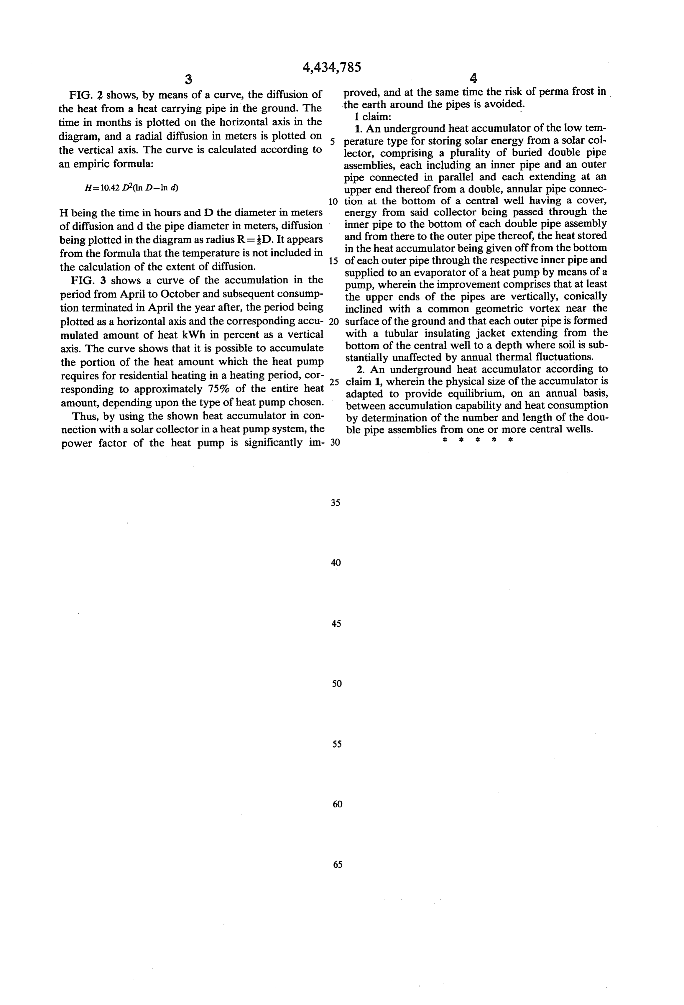
FIG. 2 shows, by means of a curve, the diffusion of proved, and at the same time the risk of permafrost in the heat from a heat carrying pipe in the ground. The theI earth claim:
around the pipes is avoided.
time in months is plotted on the horizontal axis in the 1. An underground heat accumulator of the low tem diagram, and a radial diffusion in meters is plotted on perature type for storing solar energy from a solar col the vertical axis. The curve is calculated according to lector, comprising a plurality of buried double pipe an empiric formula: assemblies, each including an inner pipe and an outer pipe connected in parallel and each extending at an
H=1042 D(ln D-lnd) upper end thereof from a double, annular pipe connec 10 tion at the bottom of a central well having a cover,
H being the time in hours and D the diameter in meters energy from said collector being passed through the of diffusion and d the pipe diameter in meters, diffusion inner pipe to the bottom of each double pipe assembly being plotted in the diagram as radius R= D. It appears and from there to the outer pipe thereof, the heat stored from the formula that the temperature is not included in 15 in
the heat accumulator being given off from the bottom each outer pipe through the respective inner pipe and the calculation of the extent of diffusion. supplied to an evaporator of a heat pump by means of a FIG. 3 shows a curve of the accumulation in the pump, wherein the improvement comprises that at least period from April to October and subsequent consump the upper ends of the pipes are vertically, conically tion terminated in April the year after, the period being inclined with a common geometric vortex near the plotted as a horizontal axis and the corresponding accu 20 surface of the ground and that each outer pipe is formed mulated amount of heat kWh in percent as a vertical with a tubular insulating jacket extending from the axis. The curve shows that it is possible to accumulate bottom of the central well to a depth where soil is sub the portion of the heat amount which the heat pump stantially 2. An unaffected by annual thermal fluctuations.
underground heat accumulator according to requires for residential heating in a heating period, cor 25 claim 1, wherein the physical size of the accumulator is responding to approximately 75% of the entire heat adapted to provide equilibrium, on an annual basis, amount, depending upon the type of heat pump chosen. between accumulation capability and heat consumption Thus, by using the shown heat accumulator in con by determination of the number and length of the dou nection with a solar collector in a heat pump system, the ble pipe assemblies from one or more se central wells.
power factor of the heat pump is significantly im 30
Provenance
- Collection
- Cited prior art
- Original PDF
- patentimages.storage.googleapis.com →
- Filed
- 1982-09-27
- Pages
- 5
- Method
- pdftotext (the PDF's own text layer) + pdftoppm 300dpi page scans
- Source
- Google Patents bibliographic record
- Granted
- 1984-03-06
- Inventors
- Niels K. Knudsen
- Transcribed from
- patentimages.storage.googleapis.com →