patent · US4267881
Heat storage sink
19 May 1981
Page 1 — bibliographic record
United
Byerly
States Patent (19) (11) 4,267,881
(54) HEAT STORAGESINK 57 ABSTRACT 76 Inventor: Cecil W. Byerly, R.R. 2, Box 917, A storage system for heat and cold exchange with a Waukee, Iowa 50263 fluid from a solar collector. The system comprises a large block of earth material which is defined at its (21) Appl. No.: 958,674 outer perimeter by a trench. The block of earth material (22 Filed: Nov. 8, 1978 has an outer zone of vertically downwardly extending channels into the block of earth material and an associ 51) Int. Cl. .............................................. F28D 21/00 ated inner zone of vertically downwardly extending 52 U.S.C. ....................................... 165/45; 126/436 channels into the block of earth material. Each of the 58) Field of Search ....................... 165/2, 45; 62/260; channels holds a conduit for passage of heat exchange 126/436, 430 fluid to provide heat exchange between the fluid and (56) References Cited the block of earth material. The earth is used for storage of heat from a solar collector. The invention also relates
3,339,629 9/1967 Hervey .................................. 165/45 heat which is withdrawn from the system is selectively 4,024,910 5/1977 Werner ................................. 165/45 withdrawn from the outer zone of vertical channels in order to provide more efficient heat withdrawal and
Primary Examiner-Donald F. Norton storage.
Attorney, Agent, or Firm-Zarley, McKee, Thomte,
Voorhees & Sease 4 Claims, 4 Drawing Figures
:2 AZZZZZZZZZZZZZZZZZZZZ
Page 2
Drawing sheet — no readable text.
Page 3
always to the outer zone. In this manner heat loss is
HEAT STORAGE SINK minimized and storage efficiency is increased. BACKGROUND OF THE INVENTION DETAILED DESCRIPTION OF THE
INVENTION
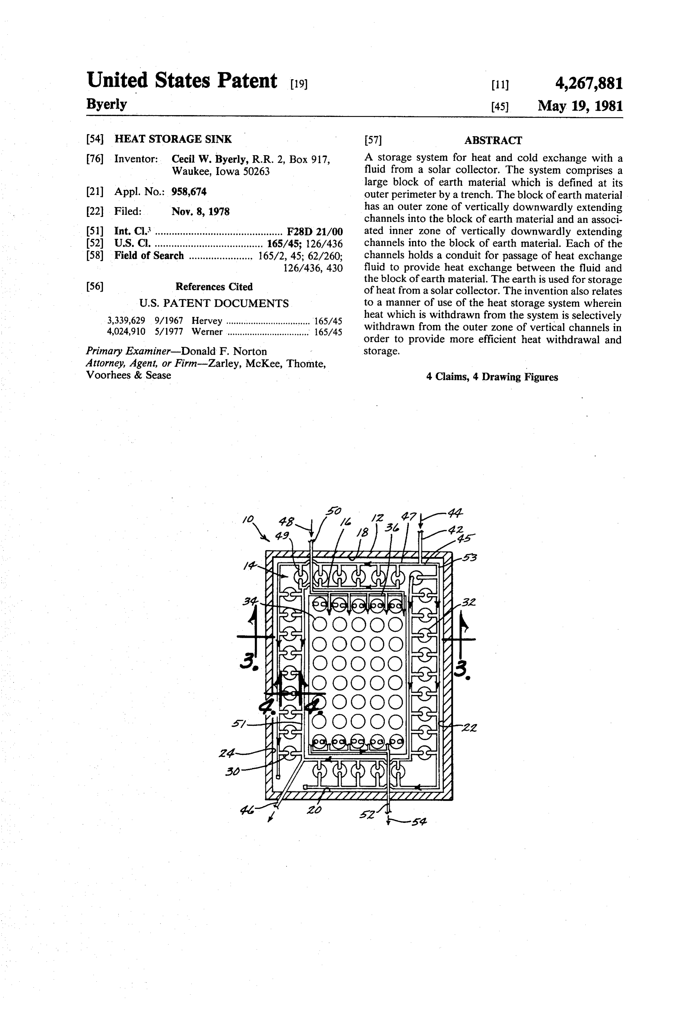
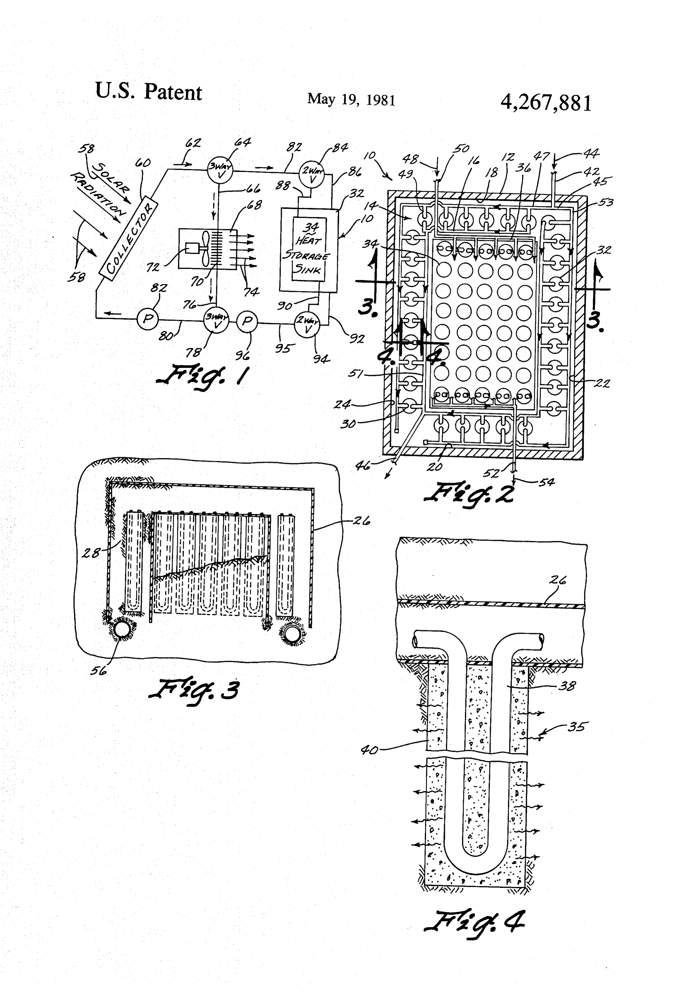
This invention relates to a storage system for heat and 5 Looking first at FIGS. 2, 3 and 4, the heat storage cold which utilizes the natural storage capabilities of the sink, soil. The system is primarily adapted for use with solar ging areferred to generally as 10, is constructed by dig collectors of the type which provide for heat exchange block oflarge perimeter trench 12 which defines a large earth material 14 having a top surface 16 and in the collector between solar radiation and a heat ex 10 vertical side walls 18, 20, 22 and 24. In order to provide change fluid passing through the collector. an insulative barrier, side walls 18, 20, 22 and 24 and the One of the problems with solar heat collection sys outer wall, defined by trench 12, are covered with a tems is that when potential collection is greatest, need is moisture impervious material, such as a vinyl coating none or minimal and no economical use of the surplus heat has been available, so as to have summer collected 15 26 isItshown 26. is, of course, to be understood that vinyl coating as exemplary only and any moisture imper heat available for winter use. Expensive storage struc vious sheet like material can be used, for example poly tures and more expensive insulation materials have ethylene sheeting, or the like. Importantly, trench 12 is, made such storing generally uneconomical. after covering its side walls with vinyl coating 26, filled This invention relates primarily to a heat storage sink with dry particulate earth material 28. Dry particulate and method which utilizes the natural heat storage 20 earth material 28 is important in that it provides an value of the soil. More particularly, the natural heat effective insulative barrier to prevent heat loss out storage value of soil is utilized in a manner which pro wardly from earth block 14. For example, the K value motes greater heating efficiency by continual selective of dry earth is about 0.032 and for example urethane withdrawal of heat, from a perimeter zone, which is foam has a K value of about 0.011. Both of these are described hereinafter. 25 measured on a per foot basis. Accordingly, the primary object of this invention is Extending downwardly into earth material block 14 to provide a new and efficient heat storage sink so that are a plurality of channels, or bores, 30. As can be seen the entire annual heat requirement may be supplied by in FIG. 2, the channel bores 30 are arranged in two the system at low cost. groupings. A first grouping, designated for illustrative Another object of this invention is to provide a new 30 purposes as 32, defines an outer zone and a second series and efficient heat storage sink which is economical of of channel bores represented at 34 defines an inner-zone, manufacture in that it utilizes as the primary storage which for illustrative purposes, is shown with an inner sink earth material. zone boundary 36.
Yet another object of this invention is to provide a Each of vertical bores 30, both in inner zone 34 and method of heat storage, and withdrawal from earth 35 outer zone 32, are filled with a heat exchange member material such that the storage capabilities of the earth which comprises a U-shaped conduit 38 embedded in can be most efficiently maximized to minimize heat loss. concrete 40, with, of course, the concrete being shaped The method of accomplishing each of the above ob for matingly fitting within bore 30.
jects as well as others will become apparent from the 40 Each of the heat exchange members 35 (see FIG. 4) in detailed description of the invention. the outer zone 32 are connected in parallel by suitable conduit and associated couplings which, since its use is
BRIEF DESCRIPTION OF THE DRAWINGS well known and does not form a part of this invention it FIG. 1 is a schematic view showing how the heat isthat only depicted schematically. However, it is important heat exchange members 35be connected in parallel, storage sink of this invention fits within an overall solar 45 as opposed to series, in order to obtain maximum heat collection heating system. transfer efficiency. Heat exchange fluid entering outer FIG. 2 is a plan view of the heat storage sink showing zone inlet 42 as depicted by arrow 44, splits at T inter schematically flow paths through the system.
FIG.3 is an elevated sectional view along line 3-3 of section 45 into two equal flow streams. The first stream enters line 47. Cross overs 49 carry a portion of the flow
FIG. 4 is an elevated sectional view showing in detail itthrough each heat exchanger 35 in outer zone 32 where
one of the channels employed in the invention. enters line 51, and from there to return line 46 for return to the collector.
SUMMARY OF THE INVENTION In like manner the second flow stream from T inter section 45 flows into line 53, through corresponding
The invention relates to a heat storage sink which 55 cross overs 49 to return line 55 and back to return line employs a large block of earthen material having a top 46 where its flow joins with the first stream for return to surface, vertical side walls which are defined by a pe the collector. As can be seen, the total flow path for rimeter trench, an outer zone of vertical channels ex each of the split portions is equal, and since the flow tending into the block of earth material, an inner zone of pipes of each are of the same dimensions, total resis vertical channels extending into the block of earth ma- 60 tance is equal which allows for uniform and equal flow terial with each of said inner and outer channels holding through both paths.
a conduit for passage of heat exchange fluid there In like fashion, each of the heat exchange members 35 through in order to provide heat exchange between the of inner zone 34 are connected in parallel fashion so that fluid and a block of earth material. heat exchange fluid passing into inner zone 34 as indi The method of the invention provides for selective 65 cated by directional arrow 48 may enter through en withdrawal of heat, initially from the perimeter or outer trance conduit 50, pass in parallel fashion through each zone of vertical channels so that heat will be transferred of heat exchange members 35 of inner zone 34 and from the inner hotter zone of the block of earth material thence outwardly through inner zone exit conduit 52 as
Page 4
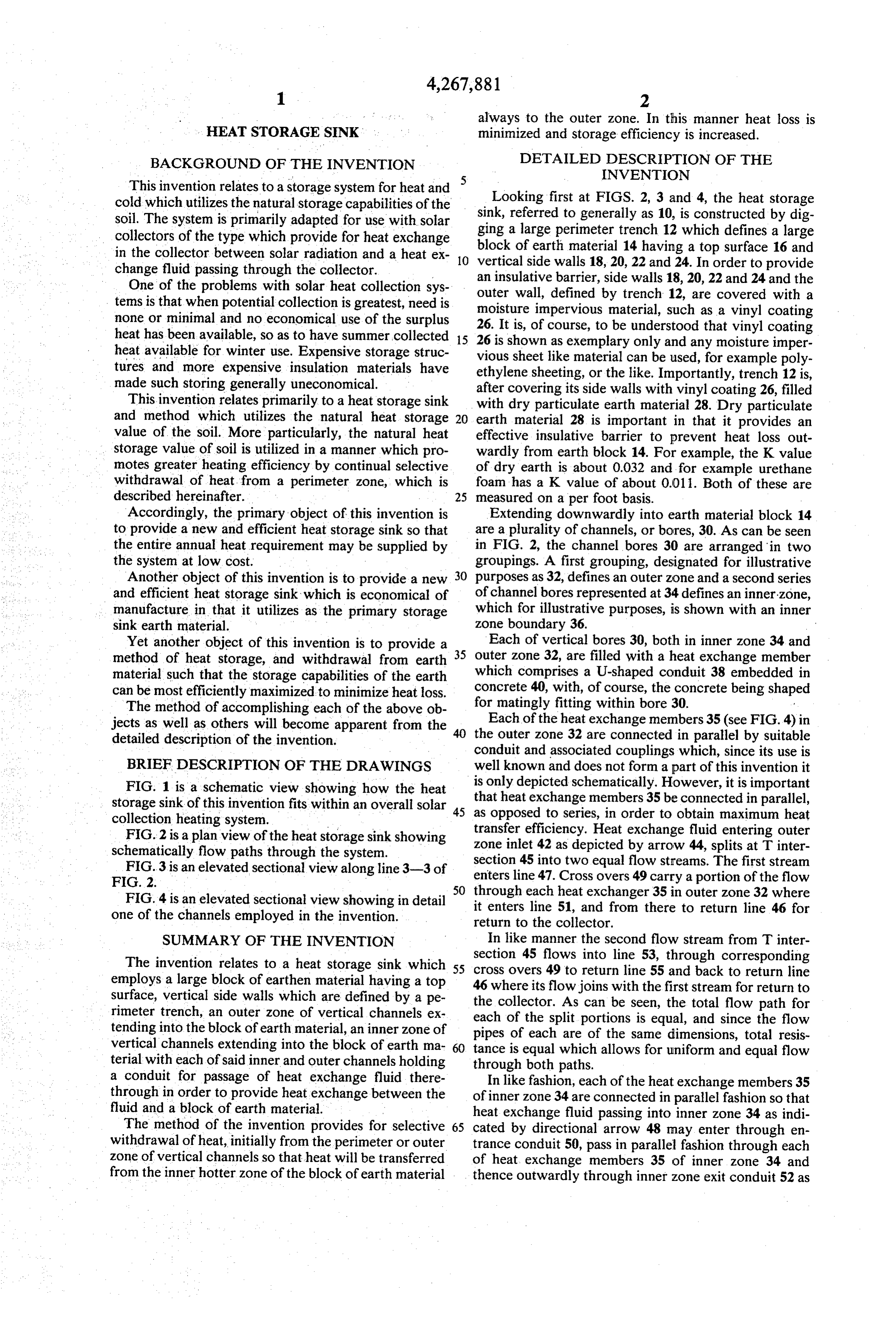
indicated by directional arrow 54. Inner Zone 34 is con rectional flow settings of each of the three way and two nected in identical flow patterns as shown for outer way valves are well known and do not form a part of zone 32, but for sake of conciseness on the entrance, and this invention and will not be described herein. It can, exit lines are schematically illustrated. however, be seen from the schematic shown in FIG. 1, The piping, or conduit members for passage of the that hot heat exchange fluid may be selectively diverted heat exchange fluid, may be made of any suitable heat into the home, back to the collector, or alternatively exchange metal, such as steel, aluminum, copper tubing, from the collector to the heat storage sink 10, and or the like. The only important criteria is that it be a within heat storage sink 10 selectively directed to the suitable heat exchanging metal. outer Zone 32 or the inner Zone 34. In like manner, It therefore can be seen that heat exchange fluid can O withdrawal from heat storage sink 10 can be selectively be passed, at the user's option, into either peripheral made from either inner zone 34 or outer zone 32 at the zone 32 or inner zone 34, and likewise may be selec user's option.
tively withdrawn from either inner zone 34 or outer An important aspect of this invention is that it has Zone 32. been found critical in every instance to provide, when After complete installation of heat sink 10 in the man 15 the system is operating in the heat storage mode, for ner herein previously described, for insulative purposes transfer of hot heat exchange fluid into the inner zone the top surface 16 is completely covered with dry par 34 of the heat storage sink 10, and when heat is passed ticulate earth material, generally from two to four feet from the stored position in heat storage sink 10 through in thickness, in order to provide an insulative, cheap and three way valve 78 and line 70 into the existing building inexpensive heat transfer barrier. This prevents out 20 structure 68 to always withdraw heat selectively in the ward heat loss to the atmosphere. first instance from outer zone 32. Only after the heating As seen in FIG. 3, at the bottom of perimeter trench demand cannot be met by stored heat from outer zone 12, if desired, the trench may be suitably tiled in order 32 is heat then withdrawn from inner zone 34. The to drain away moisture. Drain tiles 56, may have an importance of selective withdrawal on a first basis from associated sump pump in the event that the heat sink 10 25 outer zone 34, and selective storage on a first basis in is constructed in an area of a high water table. inner zone 34 is for the following reason. A temperature Looking now at FIG. 1, the operation of heat sink 10 gradient will always be maintained in this manner be in an overall solar collection system for use with a tween inner zone 34 and outer zone 32, with inner zone building structure, will be shown schematically. 34 being the hottest. The greatest potential for heat loss Solar radiation, depicted by arrows 58 hits solar col 30 is from outer zone 32 and thus stored heat is initially lector 60. Solar collector 60 may be of any desired removed therefrom before significant heat loss can oc construction, the only criteria being that it be a solar cur. In addition, outer zone 32 itself acts as a somewhat collector which employs a heat transfer fluid. Such insulative barrier to prevent outward heat loss via con collectors are well known and do not form a part of this vection from the hotter inner zone 34. In this manner, invention so will not be described in detail herein. The 35 heat loss is minimized.
heat exchange fluid which may be used in such collec As can be appreciated, if one desires the heat sink 10 tor 60 may be any heat transfer medium such as water, can be used as cold storage for effective cooling trans water glycol mixtures, or the like. Heat exchange fluid fer. Thus, at the user's option, such a system may be passes through solar collector 60, in the direction de used for home cooling.
picted by arrow 62 into a three-way diverting valve of 40 It can therefore be seen that numerous advantage conventional construction 64. If heating is desired, the exist from the use of this system. It stores surplus heat hot fluid is directed from valve 64 into line 66 and into from the solar collector in the summer and early fall for the building structure, depicted as block 68. Within the use in winter months when the collector is unable to heating space to be conditioned, represented by block supply its daily heat needs. The system utilizes an undis 68, a conventional heat exchange means depicted at 70 45 turbed block of soil as a heat sink without expensive is shown and blower fan 72 is used to blow warmed air construction. The temperature gradient maintained into the heating structure and pass it therethrough as within the block of earth material 14 allows for two represented by direction arrow 74. The now cool heat zone temperature storage in the inner zone and the exchange fluid passes out of the building structure 68 outer zone and this increases the collector efficiency via line 76 to a second three way valve 78 and from 50 while at the same time reduces perimeter heat losses there back via line 80 to solar collector 60. Pump 82 from the heat sink. Dry soil, which is kept dry by vinyl represented on line 80 is, of course, shown to provide barrier 26 acts as an effective and cheap insulation, both the power source for driving of the heat transfer fluid. on the sides of the block of earth material 14 and on its The mode of operation just described represents the top surface. The drain tile 56 around the perimeter of situation where the collected solar heat is all used for 55 the block of earth material 14 effectively directs surplus heating demand within building structure 68. water away from the soil, allowing it to maintain its dry However, in times when heating is not needed, such state and its effective heat storage capacity in that state. as summer days, the heat exchange fluid passes through Thus, as can be seen, an inexpensive heat storage sink three way valve 64, into line 82 and a first two way and method of use of the same has been provided. valve 84. From two way valve 84, depending upon 60 What is claimed is:
which lines are open or closed, the hot heat exchange 1. A storage system for heat and cold and exchange fluid may be passed into peripheral zone 32 via line 86, with a fluid from a solar collector, comprising, or alternatively into inner zone 34 via line 88. In like a large block of earth material having a top surface, manner, withdrawal from the heat storage sink 10 may and vertical side walls, said side walls being defined be selectively made from inner zone 34 via exit line 90, 65 by a perimeter trench adjacent said side walls, said or from outer zone 32 via exit line 92. Lines 90 and 92 perimeter trench being lined with moisture imper both lead to two way valve 94, line 95 and pump 96. vious material and filled with dry, particulate earth Appropriate opening and closing mechanisms, for di material,
Page 5
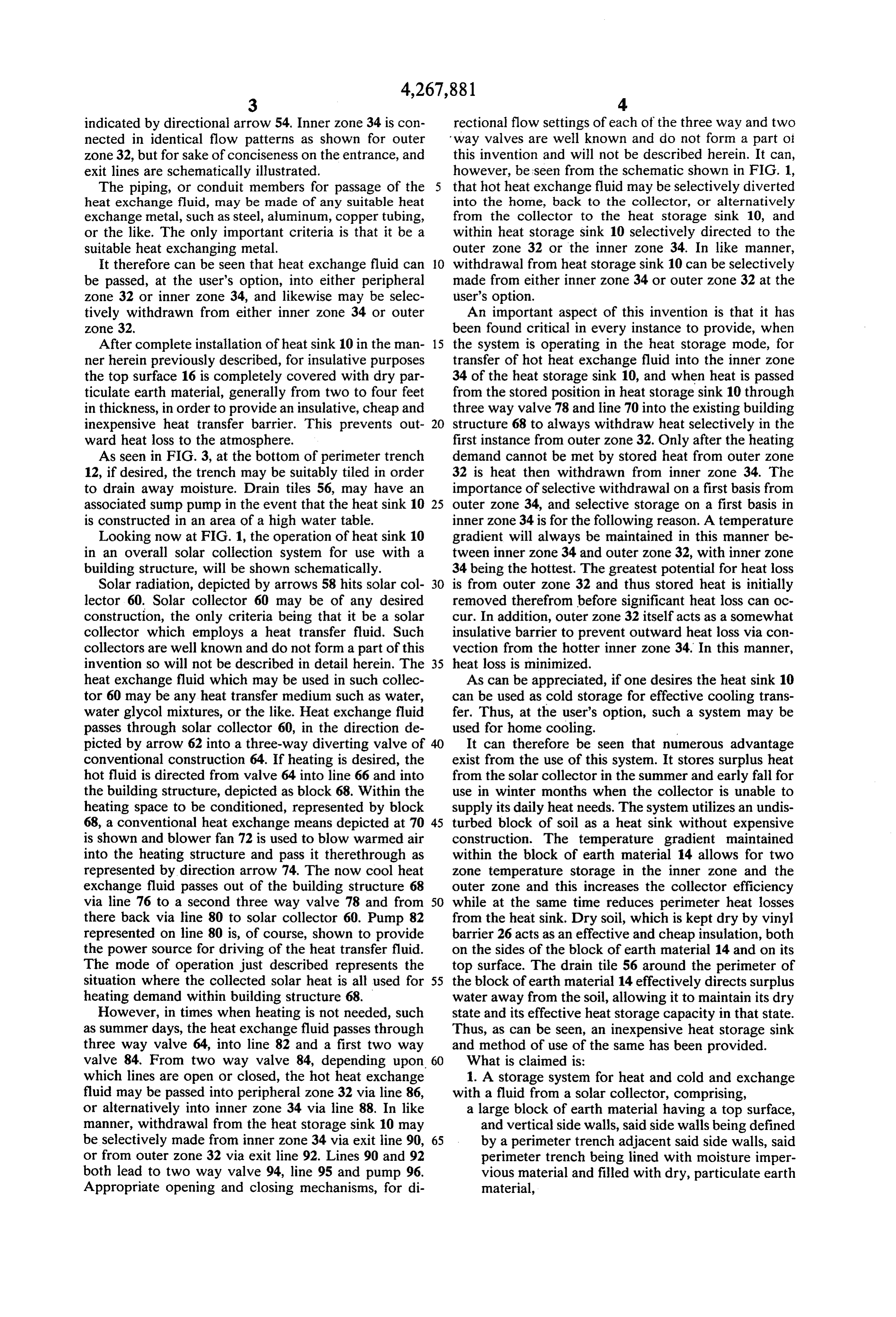
an outer zone of vertical channels extending into said 2. The storage system of claim 1 wherein the top surface of said block of earth material is covered with block of earth material, and dry particulate soil.
an inner zone of vertical channels extending into said 3. The storage system of claim 1 wherein the bottom block of earth material, of said trench is tiled to provide selective drainage of and filling each of said channels, a U-shaped conduit water away from said block of earth material. 4. The storage system of claim 1 wherein each of said embedded in concrete material and connected for outer zone and inner zones are further defined as having parallel passage of heat exchange fluid with the a fluid inlet which splits the flow into two co-equal flow other U-shaped conduits of said zone to provide O streams, with each of said streams providing uniform and equal flow to about one-half of the conduits of said heat exchange between said fluid and said block of ZOne.
earth material. sk k k sk
Provenance
- Collection
- Cited prior art
- Original PDF
- patentimages.storage.googleapis.com →
- Filed
- 1978-11-08
- Pages
- 5
- Method
- pdftotext (the PDF's own text layer) + pdftoppm 300dpi page scans
- Source
- Google Patents bibliographic record
- Granted
- 1981-05-19
- Inventors
- Cecil W. Byerly
- Transcribed from
- patentimages.storage.googleapis.com →