patent · US5184669
Heat accumulator with chemical solid matter/gas storage reactions
9 February 1993
Page 1 — bibliographic record
United States Patent (19) 11 Patent Number: 5,184,669 Tamme et al. (45) Date of Patent: Feb. 9, 1993 (54) HEAT ACCUMULATOR WITH CHEMICAL (56) References Cited SOLID MATTER/GAS STORAGE U.S. PATENT DOCUMENTS
REACTIONS
75 Inventors: Rainer Tamme, Ostfildern; Herbert 4,099,558 7/1978 Bricard et al. ........................ 165/10 Kanwischer, Stuttgart, both of Fed. 4,227,375 10/1980 Tompkins ............................. 62/27 Rep. of Germany 4,403,643 9/1983 Minto ............................. 165A104.2
(73) Assignee: Deutsche Forschungsanstalt fuer 4,484,617 11/1984 Sizmann ......................... 65/104.2 Luft- und Raumfahrt e.V., Fed. Rep. 4,535,837 8/1985 Ishii et al. .
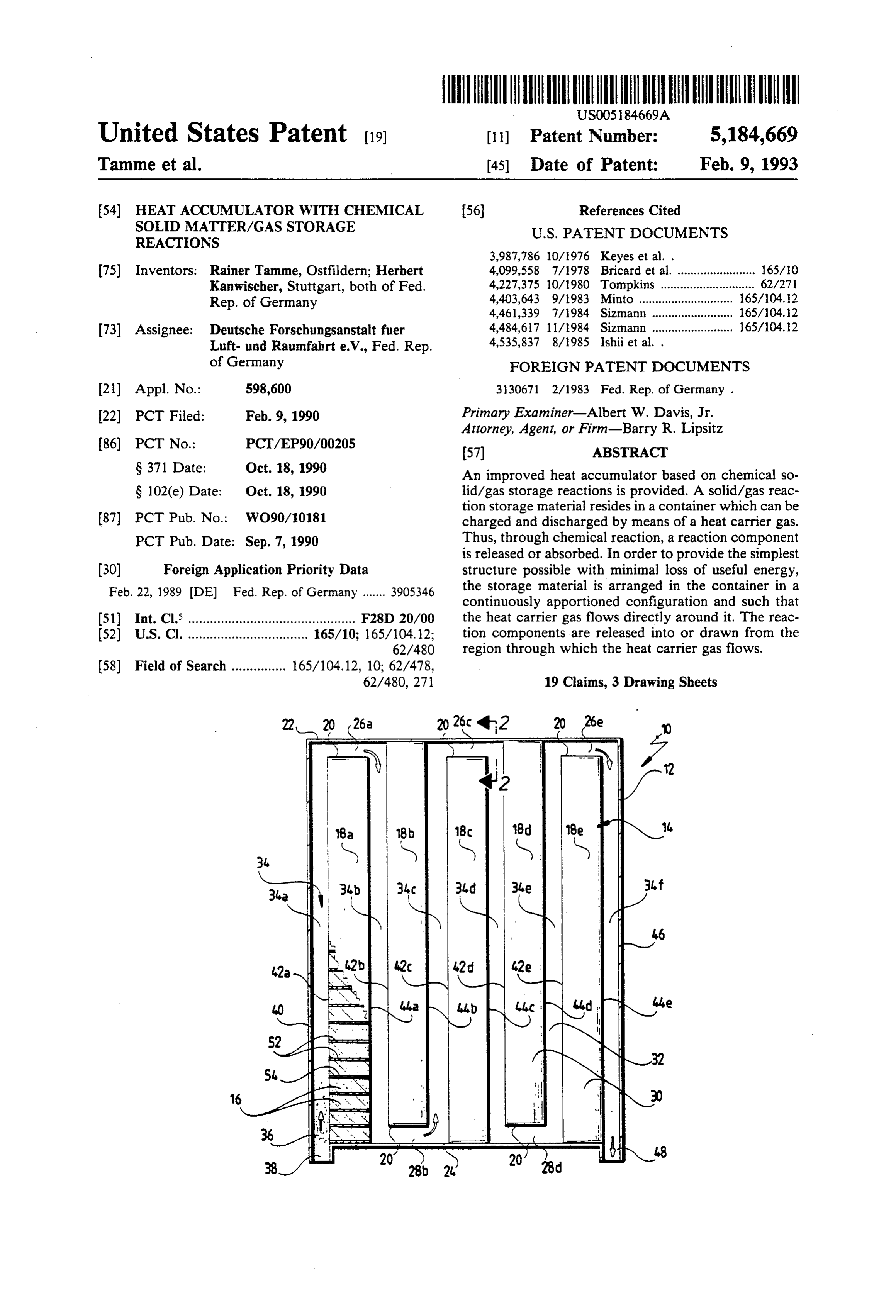
of Germany FOREIGN PATENT DOCUMENTS 2) Appl. No.: 598,600 3130671 2/1983 Fed. Rep. of Germany . 22 PCT Filed: Feb. 9, 1990 Primary Examiner-Albert W. Davis, Jr. Attorney, Agent, or Firm-Barry R. Lipsitz 86) PCT No.: PCT/EP90/00205 (57) ABSTRACT S 371 Date: Oct. 18, 1990 An improved heat accumulator based on chemical so S 102(e) Date: Oct. 18, 1990 lid/gas storage reactions is provided. A solid/gas reac tion storage material resides in a container which can be (87) PCT Pub. No.: WO90/10181 charged and discharged by means of a heat carrier gas. PCT Pub. Date: Sep. 7, 1990 Thus, through chemical reaction, a reaction component is released or absorbed. In order to provide the simplest (30) Foreign Application Priority Data structure possible with minimal loss of useful energy, Feb. 22, 1989 (DE) Fed. Rep. of Germany ....... 3905.346 the storage material is arranged in the container in a continuously apportioned configuration and such that 51) Int. Cl. .............................................. F28 D2O/OO the heat carrier gas flows directly around it. The reac 52) U.S.C. ................................. 165/10; 165/104.12; tion components are released into or drawn from the 62/480 region through which the heat carrier gas flows.
62/480, 271 19 Claims, 3 Drawing Sheets
Page 2
Drawing sheet — no readable text.
Page 3
Drawing sheet — no readable text.
Page 4
Drawing sheet — no readable text.
Page 5
the heat carrier gas, provision is made for the support
HEAT ACCUMULATOR WITH CHEMICAL SOLD structure to comprise adjacent compartments separated MATTER/GAS STORAGE REACTIONS by walls with the storage material arranged therein in the configuration in which it is divided into portions.
The invention relates to a heat accumulator operating 5 These compartments which may, for example, be ar with chemical solid matter/gas storage reactions and ranged in honeycomb-like or similar design, enable the comprising a solid matter/gas reaction storage material storage material to be arranged in a very expedient arranged in a container and being chargeable and dis manner such that the heat carrier gas flows around it. chargeable by means of a heat carrier gas, thereby re It has proven particularly advantageous for the con spectively releasing and taking in a reaction component 10 partments to be adapted for the heat carrier gas to flow by chemical reaction. through them so the exchange of the reaction compo In such accumulators with chemical storage reactions nent does not take place by diffusion in one direction of hitherto design, a heat carrier circuit was provided only, but in several directions.
for the charging and discharging of the accumulator but The simplest structural solution for such compart transportation of the reaction component was separate 5 ments makes provision for the compartments to have from the heat carrier gas circuit. These solutions all openings on opposite sides thereof which are then filled have the disadvantage that they involve high losses of either completely or at least partially with the storage useful energy, additional supplementary energy, consid material.
erable material expenditure and, finally, also a reduced Above all, when the support structure includes sev filling factor so such chemical accumulators are, in the 20 eral elements comprising compartments, the surface of end, economically uninteresting. the storage material exposed to the heat carrier gas can The object underlying the invention is, therefore, to be enlarged in a very favorable way. so improve a heat accumulator with chemical solid It is particularly expedient for the elements to have matter/gas storage reactions that it is economically the heat carrier gas flow around them and for it to interesting, i.e., in particular, that it can be implemented 25 thereby contact them on all sides thereof. with as low structural expenditure as possible and, in A preferred solution makes provision for the ele addition, exhibits low losses of useful energy. ments to be arranged in spaced relation to one another This object is accomplished in accordance with the in the container so they form between them channels invention with a heat accumulator of the kind described through which the heat carrier gas then flows. at the beginning by the storage material being perma 30 One possibility for these channels to have the heat nently arranged in the container in a configuration in carrier gas flow through them makes provision for the which it is divided into portions with the heat carrier elements to form labyrinth-like channels for the heat gas flowing directly around it, and the storage material carrier gas between them so as to obtain an effective giving off the reaction component into and taking it in exchange of the reaction component between the heat from the space through which the heat carrier gas 35 carrier gas and the storage material with as large a flows. surface as possible. It is particularly advantageous for In this way, above all, the loss of useful energy re the elements to have the heat carrier gas flow around ferred to at the beginning was avoided. In addition, a them one after the other so that with a predetermined solution was provided which is very simple from a flow velocity of the heat carrier gas, the period of time structural viewpoint and also allows a high filling fac during which an exchange of the reaction component tO. can take place between the heat carrier gas and the A zeolite accumulator with a flow occurring directly storage medium is as long as possible. around the storage material is known from DE-A-31 30 As an alternative to this, it is, however, also possible 671. However, the zeolite accumulators are adsorp for the elements to have the heat carrier gas flow tion/desorption accumulators and not chemical accu 45 around them parallel to one another. mulators. In the description of the embodiments so far, nothing The characteristic features of chemical accumulators was said about how the support structure is to be advan are significant changes in mass and volume during the tageously designed. In an advantageous embodiment, it respective charging and discharging reaction. For ex is conceivable for the support structure to be made of ample, the changes in volume lie in the order of magni 50 ceramic material, preferably of a honeycomb ceramic tude of between 25 and 55%. This is accompanied by a material.
change in the physical properties of the storage mate As an alternative to this, it is, however, also possible rial. A granulated material as used in zeolite accumula for the support structure to be made of metal. tors, would, if used as cut material, be compacted into a Nor have any details been given so far regarding the block after a few cycles. 55 storage material. Provision is preferably made for the Therefore, in order to ensure an effective exchange of storage material to have such properties that the reac the reaction component with the heat carrier gas, provi tion component can condense at room temperature so it sion is advantageously made for the storage material can be removed from the heat carrier gas in a simple disposed in a configuration in which it is divided into way.
portions to be arranged in a support structure which is Particularly preferred embodiments make provision open towards the heat carrier gas. This support struc for the storage material to comprise alkaline oxides or ture offers the possibility of arranging the storage mate alkaline earth oxides in the charged state or alkaline rial such that it exhibits as large a surface as possible hydroxides or alkaline-earth hydroxides in the dis towards the heat carrier gas and hence an effective charged state so the reaction component given off to the exchange of the reaction component is possible even 65 heat carrier gas or taken in from the latter is water. with very great changes in volume and properties. In the variants of the inventive heat accumulator In a structurally particularly simple and advanta presented so far, it was not explained how the heat geous variant of such a support structure open towards accumulator is to be advantageously designed so as to
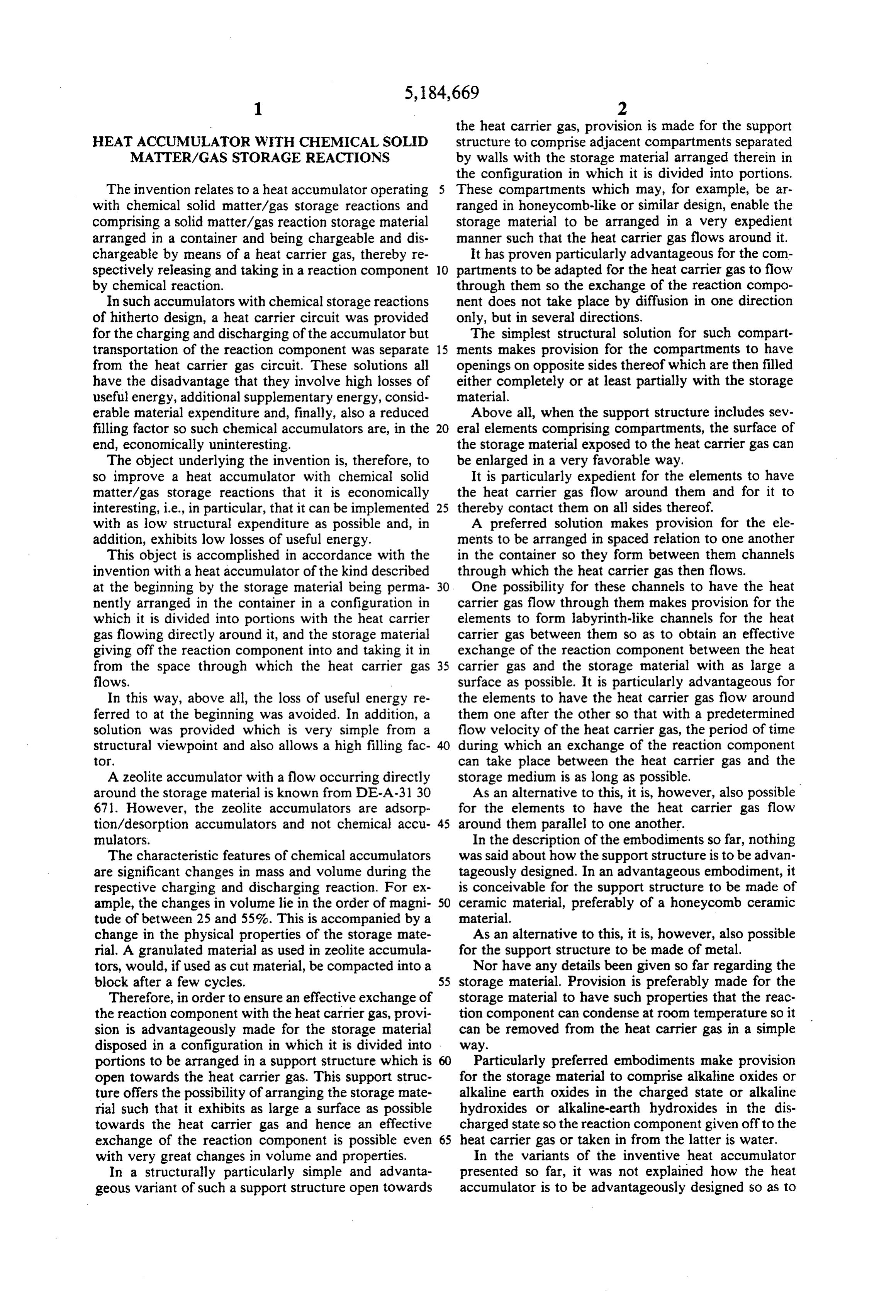
Page 6
remove the reaction component from or feed it to the 44b of element 18b and the end face 42c of element 18c heat carrier gas. as far as a gap 26c, then again a channel 34d as far as a A preferred embodiment makes provision for the heat gap 28d and from this a channel 34e as far as a gap 26e, carrier gas emerging from the container during the from which a last section 34f then leads between the charging of the storage material to be conducted via a end wall 46 opposite the end wall 40 and the end face condenser for the reaction component so that the reac 44e to a second connection 48. tion component can be removed in a simple way with As may be seen, in particular, from FIG. 2, the ele the condenser. ments 18a to e are constructed so as to comprise a plu It is, furthermore, advantageous for the heat carrier rality of parallel walls 50 and a plurality of walls 52 gas fed to the container during the discharging of the O extending perpendicularly to the walls 50, thereby to storage material to flow through a supply device for the gether forming compartments 54 of right parallelepiped reaction component arranged ahead of the container so shape which are open towards the end faces 42 and 44, the reaction component, for example, in gaseous form, in FIG. 2 42c and 44c. The storage material 16 is then can be added via this supply device to the heat carrier arranged in these compartments 54, thereby preferably gas which then transports it into the container. 15 filling the compartments 54 partially or completely. As an alternative to the last-mentioned design of the Hence an exchange of the reaction component to be heat accumulator, it is, however, also conceivable to given off into or taken in from the heat carrier gas 36 provide a supply device with which the reaction com can take place between the heat carrier gas 36 flowing ponent is introducible into the container during the through the channel 34 and the storage material 56 via discharging, i.e., for example, the condensed reaction 20 the end faces 42 and 44 of elements 18. component is introduced into the container itself in the A second embodiment of the inventive heat accumu form of a spray. lator, designated in its entirety 60, illustrated in FIG. 3, To avoid heat carrier gas losses, it is particularly likewise comprises a storage container 62 in which advantageous within the scope of the present invention there is arranged a support structure 64 which likewise for the heat carrier gas to be conducted in a circuit and 25 includes a plurality of elements 68 arranged parallel to for the reaction component to be removable from and one another for accommodating the solid matter stor addable to the heat carrier gas in this circuit. age material 66.
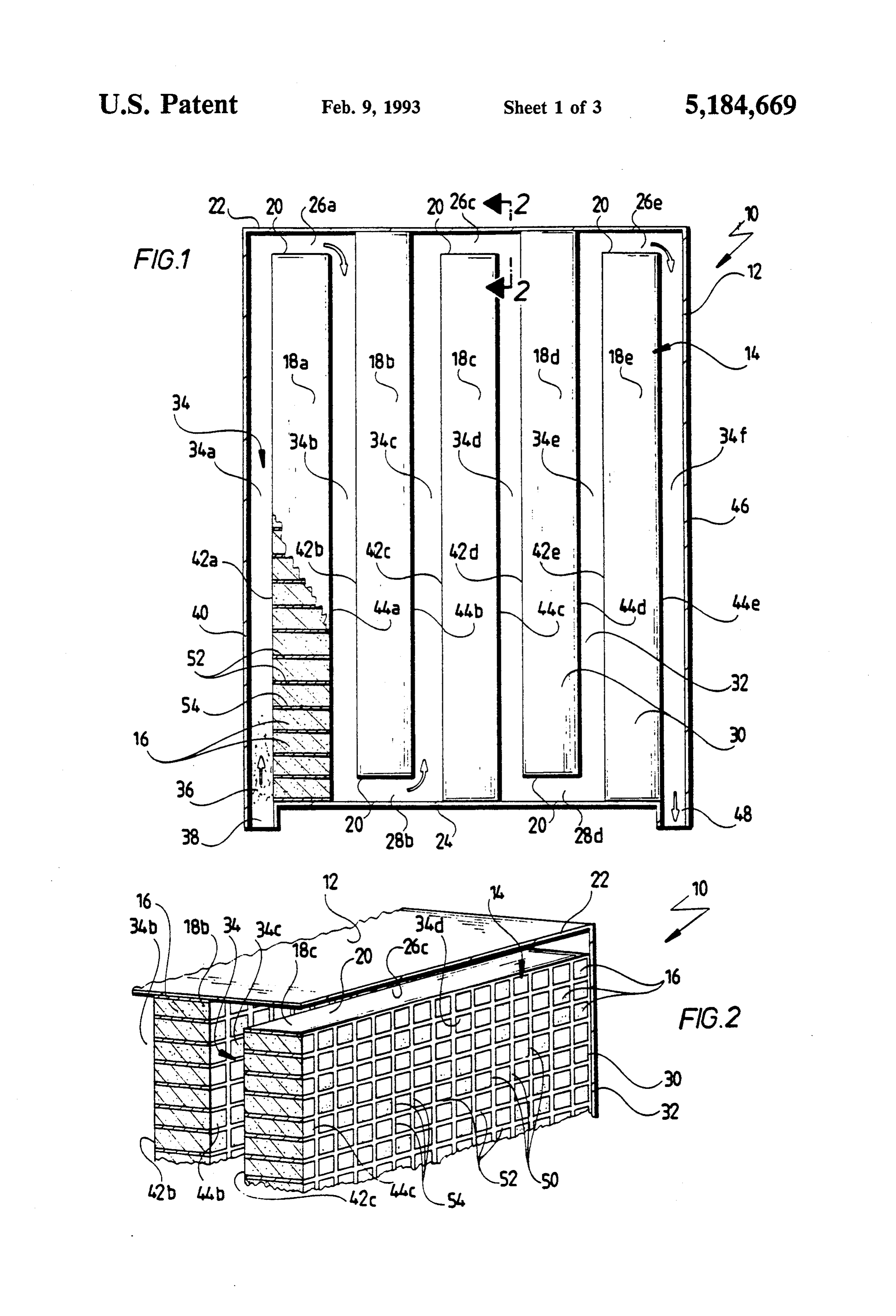
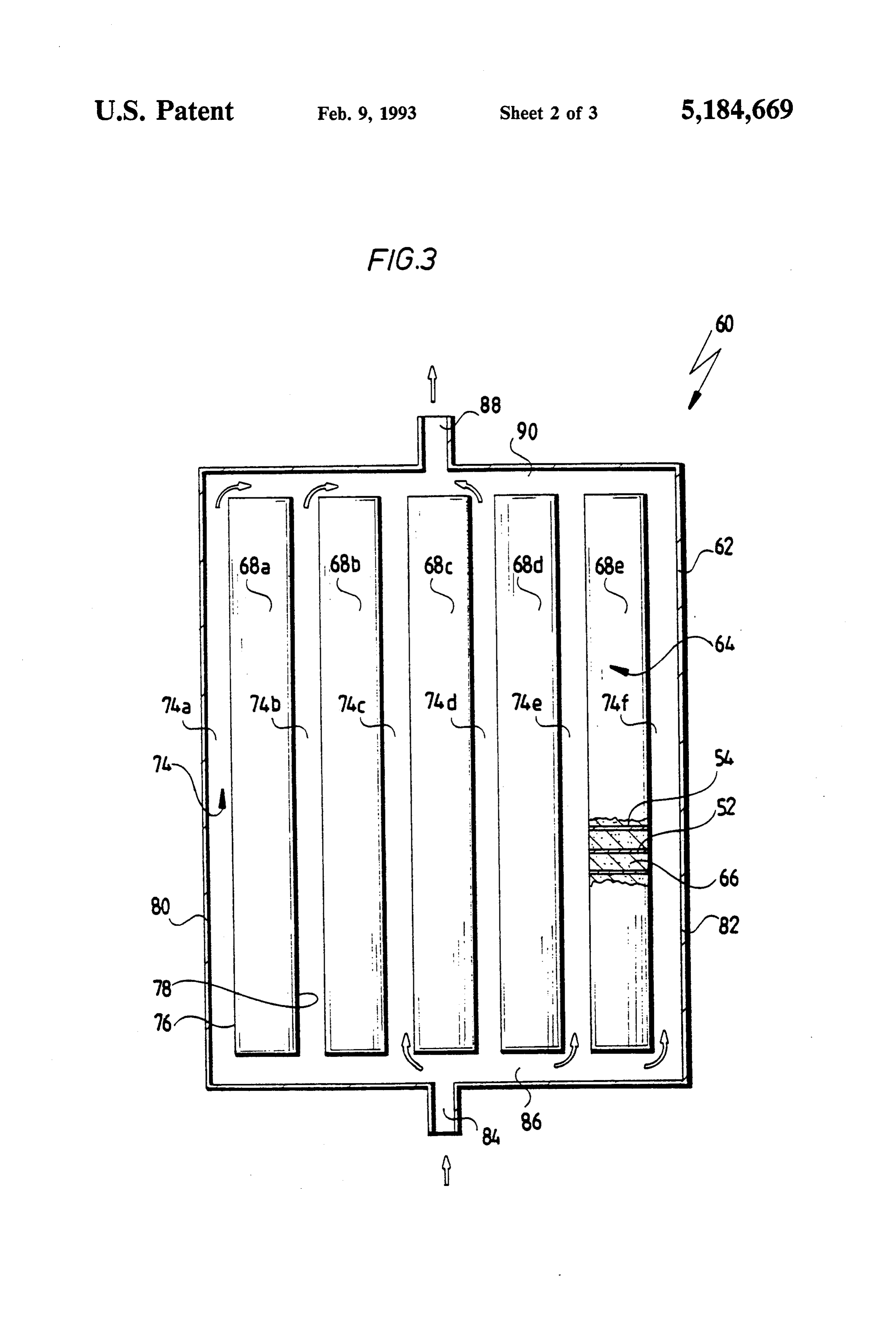
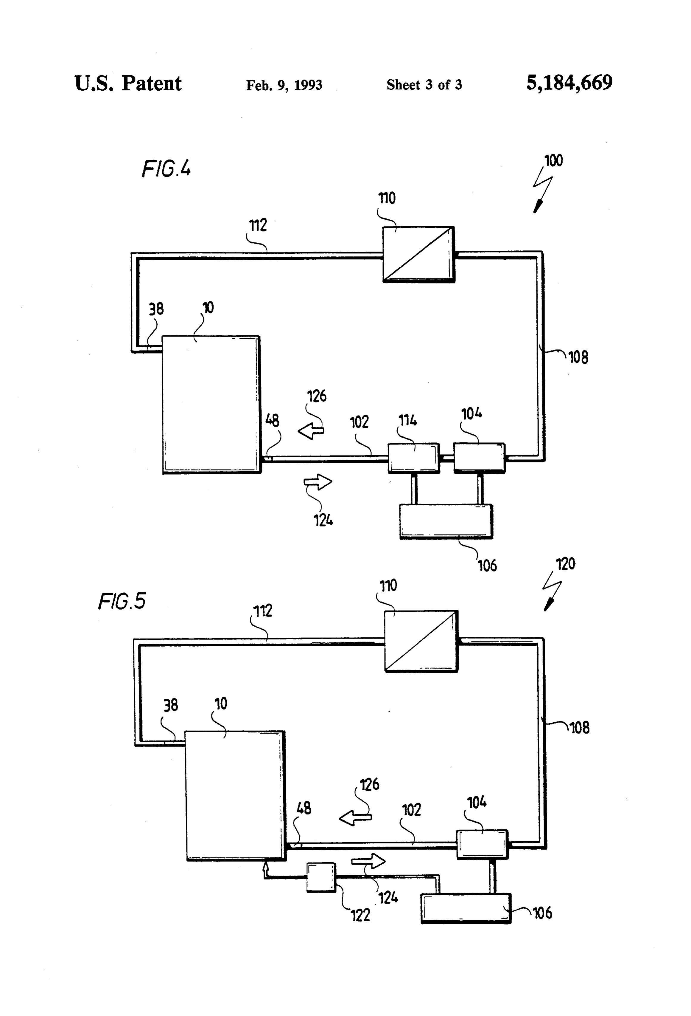
Further features and advantages of the inventive In contrast with the first embodiment, the elements solution are the subject matter of the following descrip 68a to e are arranged in such spaced relation to one tion and the drawings of several embodiments. The 30 another that they form a plurality of parallel channels drawings show: 74a tof which are delimited by the end faces 76 and 78 FIG. 1 a first embodiment of an inventive heat accu of the elements 68a and e and in the case of elements 68a mulator; and e also by the end walls 80 and 82 and lead from a FIG. 2 a perspective illustration of a partial section first transverse channel 86 connected to a first connec through the heat accumulator according to FIG. 1; 35 tion 84 to a second transverse channel 90 connected to FIG. 3 a second embodiment of an inventive heat a second connection 88.
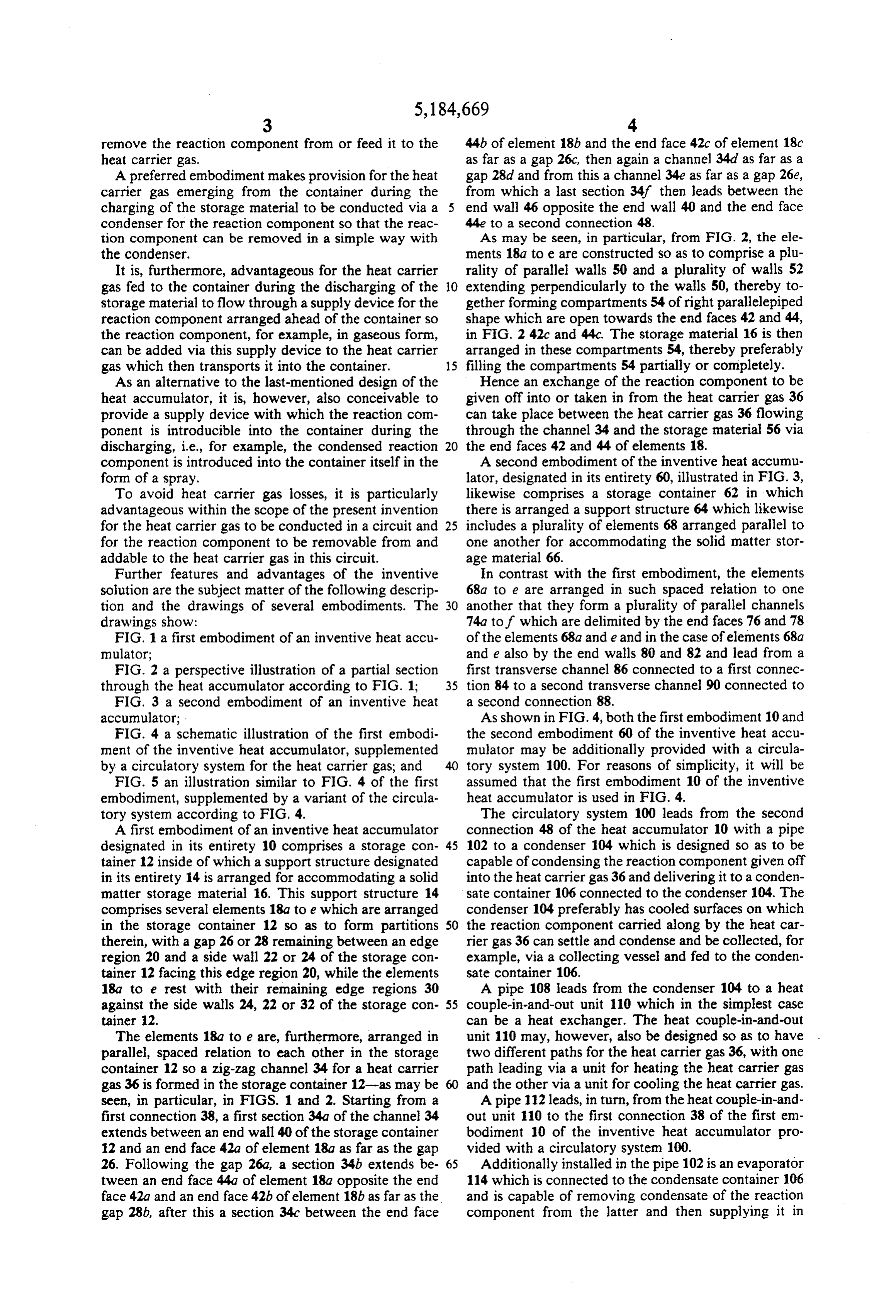
accumulator; As shown in FIG. 4, both the first embodiment 10 and FIG. 4 a schematic illustration of the first embodi the second embodiment 60 of the inventive heat accu ment of the inventive heat accumulator, supplemented mulator may be additionally provided with a circula by a circulatory system for the heat carrier gas; and tory system 100. For reasons of simplicity, it will be FIG. 5 an illustration similar to FIG. 4 of the first assumed that the first embodiment 10 of the inventive embodiment, supplemented by a variant of the circula heat accumulator is used in FIG. 4. tory system according to FIG. 4. The circulatory system 100 leads from the second A first embodiment of an inventive heat accumulator connection 48 of the heat accumulator 10 with a pipe designated in its entirety 10 comprises a storage con 45 102 to a condenser 104 which is designed so as to be tainer 12 inside of which a support structure designated capable of condensing the reaction component given off in its entirety 14 is arranged for accommodating a solid into the heat carrier gas 36 and delivering it to a conden matter storage material 16. This support structure 14 sate container 106 connected to the condenser 104. The comprises several elements 18a to e which are arranged condenser 104 preferably has cooled surfaces on which in the storage container 12 so as to form partitions 50 the reaction component carried along by the heat car therein, with a gap 26 or 28 remaining between an edge rier gas 36 can settle and condense and be collected, for region 20 and a side wall 22 or 24 of the storage con example, via a collecting vessel and fed to the conden tainer 12 facing this edge region 20, while the elements sate container 106.
18a to e rest with their remaining edge regions 30 A pipe 108 leads from the condenser 104 to a heat against the side walls 24, 22 or 32 of the storage con 55 couple-in-and-out unit 110 which in the simplest case tainer 12. can be a heat exchanger. The heat couple-in-and-out The elements 18a to e are, furthermore, arranged in unit 110 may, however, also be designed so as to have parallel, spaced relation to each other in the storage two different paths for the heat carrier gas 36, with one container 12 so a zig-zag channel 34 for a heat carrier path leading via a unit for heating the heat carrier gas gas 36 is formed in the storage container 12-as may be 60 and the other via a unit for cooling the heat carrier gas. seen, in particular, in FIGS. 1 and 2. Starting from a A pipe 112 leads, in turn, from the heat couple-in-and first connection 38, a first section 34a of the channel 34 out unit 110 to the first connection 38 of the first em extends between an end wall 40 of the storage container bodiment 10 of the inventive heat accumulator pro 12 and an end face 42a of element 18a as far as the gap vided with a circulatory system 100. 26. Following the gap 26a, a section 34b extends be 65 Additionally installed in the pipe 102 is an evaporator tween an end face 44a of element 18a opposite the end 114 which is connected to the condensate container 106 face 42a and an end face 42b of element 18b as far as the and is capable of removing condensate of the reaction gap 28b, after this a section 34c between the end face component from the latter and then supplying it in
Page 7
evaporated form to the heat carrier gas 36 flowing in With the circulatory system 120, circulation of the the pipe 102. heat carrier gas likewise takes place in the direction of In a combination of the first embodiment 10 of an arrow 126 during the discharging of the storage mate inventive heat accumulator with a variant 120 of the rial 16, i.e., in the direction opposite to direction 124, circulatory system 100, the difference over the latter with the condensate injector 122 introducing the con resides in provision of a condensate injector 122 instead densed reaction component directly into the storage of the evaporator 114 for removing condensate of the container, for example, in the form of a spray which is reaction component from the condensate container 106 then, in turn, distributed by the heat carrier gas 36 and injecting it directly into the storage container 12, through the storage container 12 and reacts with the for example, in the form of a spray. Such condensate O storage material via the end faces 42 and 44 of elements injection can be carried out either exclusively in the 18 so the storage material 16 heats up again. The devel region of the connection 48 or at several points along oping heat is likewise conducted by the heat carrier gas the channel 34, i.e., in particular, in the region of the 36 via the pipe 112 to the heat couple-in-and-out unit gaps 26 and 28 in order to achieve uniform distribution 110 in which the heat energy is then removed from the of the condensate in the storage container 12. 15 heat carrier gas.
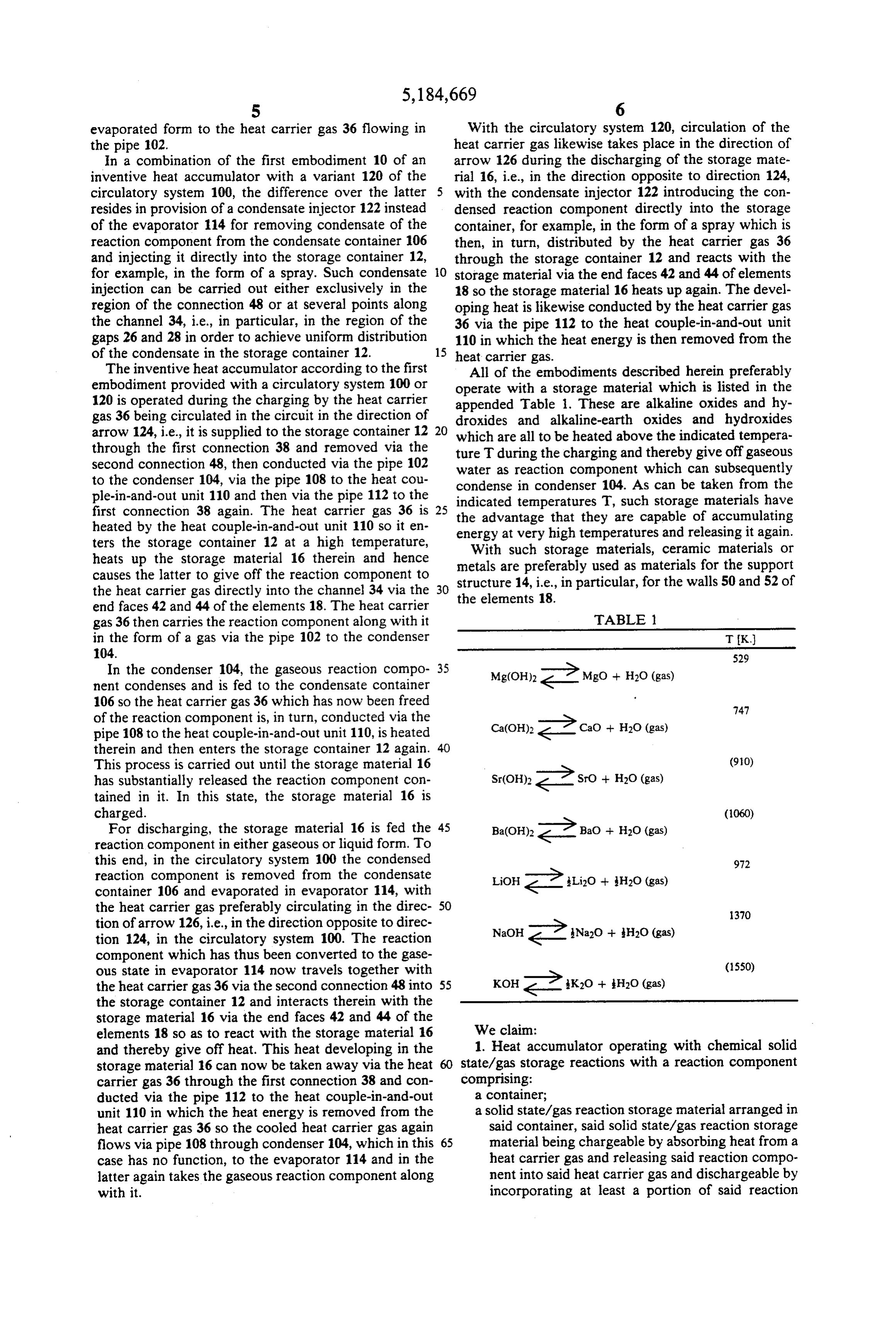
The inventive heat accumulator according to the first All of the embodiments described herein preferably embodiment provided with a circulatory system 100 or operate with a storage material which is listed in the 120 is operated during the charging by the heat carrier appended Table i. These are alkaline oxides and hy gas 36 being circulated in the circuit in the direction of droxides and alkaline-earth oxides and hydroxides arrow 124, i.e., it is supplied to the storage container 12 20 which are all to be heated above the indicated tempera through the first connection 38 and removed via the ture T during the charging and thereby give off gaseous second connection 48, then conducted via the pipe 102 water as reaction component which can subsequently to the condenser 104, via the pipe 108 to the heat cou condense in condenser 104. As can be taken from the ple-in-and-out unit 110 and then via the pipe 112 to the indicated temperatures T, such storage materials have first connection 38 again. The heat carrier gas 36 is 25 the advantage that they are capable of accumulating heated by the heat couple-in-and-out unit 110 so it en energy at very high temperatures and releasing it again. ters the storage container 12 at a high temperature, With such storage materials, ceramic materials or heats up the storage material 16 therein and hence metals are preferably used as materials for the support causes the latter to give off the reaction component to structure 14, i.e., in particular, for the walls 50 and 52 of the heat carrier gas directly into the channel 34 via the 30 the elements 18.
end faces 42 and 44 of the elements 18. The heat carrier gas 36 then carries the reaction component along with it TABLE 1 in the form of a gas via the pipe 102 to the condenser T K.)
In the condenser 104, the gaseous reaction compo 35 Mg(OH)2 2Mgo + H2O (gas) 529 nent condenses and is fed to the condensate container 106 so the heat carrier gas 36 which has now been freed of the reaction component is, in turn, conducted via the Ca(OH)2 - ?cao + H2O (gas) 747 pipe 108 to the heat couple-in-and-out unit 110, is heated therein and then enters the storage container 12 again.
This process is carried out until the storage material 16 has substantially released the reaction component con Sr(OH)2 2 SrO + H2O (gas) (910) tained in it. In this state, the storage material 16 is charged.
For discharging, the storage material 16 is fed the 45 Ba(OH)2 2 Bao + H2O (gas) (1060) reaction component in either gaseous or liquid form. To this end, in the circulatory system 100 the condensed reaction component is removed from the condensate LiOH - ? Li2O + H2O (gas) 972 container 106 and evaporated in evaporator 114, with the heat carrier gas preferably circulating in the direc 50 tion of arrow 126, i.e., in the direction opposite to direc NaOH - ? Na2O + H2O (gas) 370 tion 124, in the circulatory system 100. The reaction component which has thus been converted to the gase ous state in evaporator 114 now travels together with KOH 2 K2O + H2O (gas) (1550) the heat carrier gas 36 via the second connection 48 into 55 the storage container 12 and interacts therein with the storage material 16 via the end faces 42 and 44 of the elements 18 so as to react with the storage material 16 We claim:
and thereby give off heat. This heat developing in the 1. Heat accumulator operating with chemical solid storage material 16 can now be taken away via the heat 60 state/gas storage reactions with a reaction component carrier gas 36 through the first connection 38 and con comprising:
ducted via the pipe 112 to the heat couple-in-and-out a container;
unit 110 in which the heat energy is renoved from the a solid state/gas reaction storage material arranged in heat carrier gas 36 so the cooled heat carrier gas again said container, said solid state/gas reaction storage flows via pipe 108 through condenser 104, which in this 65 material being chargeable by absorbing heat from a case has no function, to the evaporator 114 and in the heat carrier gas and releasing said reaction compo latter again takes the gaseous reaction component along nent into said heat carrier gas and dischargeable by with it. incorporating at least a portion of said reaction
Page 8
component introduced into said container and re such that said reaction component can condense at leasing heat into said heat carrier gas; room temperature.
a support structure within said container, said support 14. Heat accumulator as defined in claim 1, character structure comprising separate compartments that ized in that said storage material comprises alkaline are open towards said heat carrier gas; oxides or alkaline-earth oxides in the charged state and said storage material being permanently arranged in alkaline hydroxides or alkaline-earth hydroxides in the said separate components and divided by into por discharged
state.
accumulator as defined in claim 1, character tions within said compartments; and said heat carrier gas flowing directly around said 10 tainer during the charging ofgassaid ized in that said heat carrier exiting from said con storage material is portions of said storage material for releasing said conducted via a condenser for said reaction component. reaction component into and having said reaction component incorporated from the space through ized in that said heat carrier gas fed to said character 16. Heat accumulator as defined in claim 1, container which said heat carrier gas flows. during the discharging of said storage material flows 2. Heat accumulator as defined in claim 1, character 15 through a supply device for said reaction component ized in that said open support structure comprises adja arranged ahead of said container.
cent compartments separated by walls and said storage 17. Heat accumulator as defined in claim 1, character material is arranged in said compartments in said config ized in that a supply device is provided for introducing uration in which it is divided into portions. said reaction component into said container during the 3. Heat accumulator as defined in claim 2, character 20 discharging of said storage material. ized in that said compartments are adapted to have said 18. Heat accumulator as defined in claim 1, character heat carrier gas flow through them. ized in that said heat carrier gas is supplied in a circuit, 4. Heat accumulator as defined in claim 2, character and in that said reaction component can be removed ized in that said compartments (54) have openings on from and fed to said heat carrier gas in this circuit. opposite sides thereof. 25 19. Heat accumulator operating with chemical solid 5. Heat accumulator as defined in claim 2, character state/gas storage reactions with a reaction component ized in that said support structure includes several ele comprising:
ments comprising compartments. a container;
6. Heat accumulator as defined in claim 5, character a solid state/gas reaction storage material arranged in ized in that said elements have said heat carrier gas flow 30 said container, said solid state/gas reaction storage around them. material being chargeable by absorbing heat from a 7. Heat accumulator as defined in claim 6, character heat carrier gas and releasing said reaction compo ized in that said elements are arranged in spaced relation nent into said heat carrier gas and dischargeable by to one another in said container. incorporating at least a portion of said reaction 8. Heat accumulator as defined in claim 7, character 35 component introduced into said container and re ized in that said elements form between them labyrinth leasing heat into said heat carrier gas; like channels for said heat carrier gas. a support structure within said container, said support structure comprising separate compartments that 9. Heat accumulator as defined in claim 8, character are open towards said heat carrier gas; ized in that said elements have said heat carrier gas flow said storage material being permanently arranged in around them one after the other. aid separate compartments and divided into por 10. Heat accumulator as defined in claim 7, character tions within said compartments; ized in that said elements have said heat carrier gas flow said portions being arranged in planes above each around them parallel to one another. other with several separated portions being ar 11. Heat accumulator as defined in claim 1, character 45 ranged on said planes; and ized in that said support structure is made of ceramic said heat carrier gas flowing directly around said material. portions of said storage material for releasing said 12. Heat accumulator as defined in claim 1, character reaction component into and having said reaction ized in that said support structure is made of metal. component incorporated from the space through 13. Heat accumulator as defined in claim 1, character SO which said heat kcarrier
gasr flows.
ized in that the properties of said storage material are
Page 9
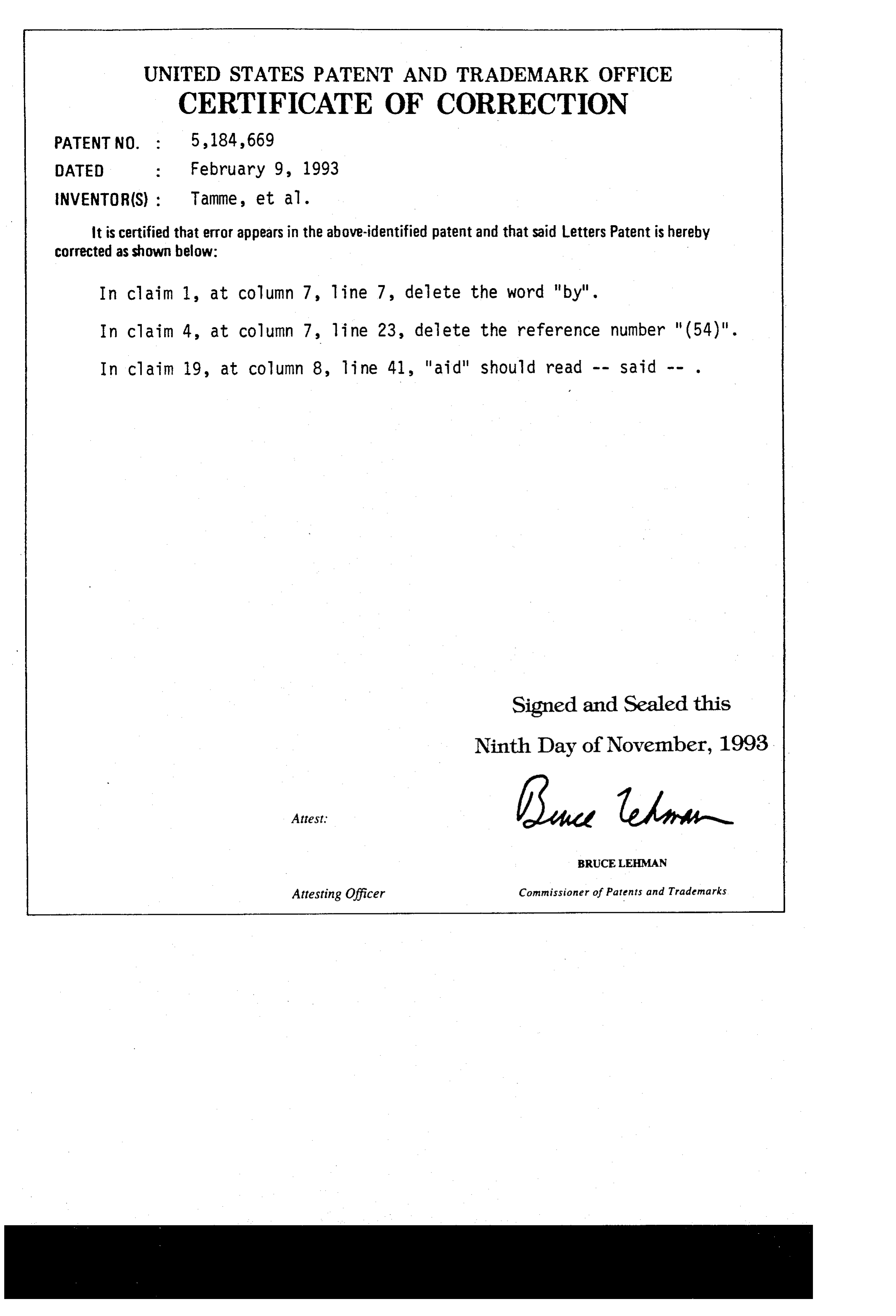
UNITED STATES PATENT AND TRADEMARK OFFICE
CERTIFICATE OF CORRECTION
NVENTOR(S) : Tamme, et al.
it is certified that error appears in the above-identified patent and that said Letters Patent is hereby corrected as shown below:
In claim 1, at column 7, line 7, delete the Word "by". In claim 4, at column 7, line 23, delete the reference number "(54)". In claim 19, at Column 8, line 41, "aid" should read -- Said -- .
Signed and Sealed this
Ninth Day of November, 1993
BRUCE LEHMAN
Attesting Officer Connissioner of Patents and Trademarks
Provenance
- Collection
- Cited prior art
- Original PDF
- patentimages.storage.googleapis.com →
- Filed
- 1990-02-09
- Pages
- 9
- Method
- pdftotext (the PDF's own text layer) + pdftoppm 300dpi page scans
- Source
- Google Patents bibliographic record
- Granted
- 1993-02-09
- Inventors
- Rainer Tamme; Herbert Kanwischer; Deutsches Zentrum fuer Luft und Raumfahrt eV
- Transcribed from
- patentimages.storage.googleapis.com →