patent · US4850424
Heat accumulator
25 July 1989
Page 1 — bibliographic record
United States Patent (19) 11 Patent Number: 4,850,424 Mitani et al. 45 Date of Patent: Jul. 25, 1989 (54) HEAT ACCUMULATOR FOREIGN PATENT DOCUMENTS 75 Inventors: Akio Mitani; Koji Kashima; Hiroichi 96854 7/1980 Japan ..................................... 165/10 Yamaguchi, all of Yokohama, Japan
Primary Examiner-Albert W. Davis, Jr.
73 Assignee: Kabushiki Kaisha Toshiba, Kawasaki, Attorney, Agent, or Firm-Cushman, Darby & Cushman Japan 57 ABSTRACT 21 Appl. No.: 149,078 A heat accumulator includes a heat storage tank and a latent heat accumulating material which fills the tank.
22 Filed: Jan. 27, 1988 The heat accumulating material remains in a stable su 30 Foreign Application Priority Data percooled condition at temperatures lower than a pre determined phase transformation temperature, and is
Jan. 31, 1987 JPl, Japan .................................. 62-21046 released from the supercooled condition by a releasing 51 Int. Cl.' .............................................. F28D 20/00 device. The releasing device includes a holding mem 52 U.S.C. ........................................ 165/10; 165/12; ber, which is mounted on the storage tank such that it is
capable of touching the accumulating material and 58) Field of Search ...................... 165/104.11, 10, 13, which holds a seed material. A driving mechanism 165/12; 126/263 drives the holding member so that the seed material comes into contact with the heat accmulating material (56) References Cited for a predetermined period of time, releasing the latter
from its supercooled condition.
2,289,425 7/1942 Hogan ................................. 26/263 13 Claims, 4 Drawing Sheets
SUPERCOOLING
8 COMMAND
REEASING
CONTROL
CRCUIT
DRVNG
POWER
SOURCE
HEATER
44242 ZZZZZZZZ277 s POWER
SOURCE
Page 2
Drawing sheet — no readable text.
Page 3
Drawing sheet — no readable text.
Page 4
Drawing sheet — no readable text.
Page 5
Drawing sheet — no readable text.
Page 6
ing material from its supercooled condition but without
HEAT ACCUMULATOR causing degradation of the physical properties of the accumulating material.
BACKGROUND OF THE INVENTION To achieve the above object, a heat accumulator This invention relates to a heat accumulator and more according to this invention comprises a heat storage particularly to a heat accumulator using a latent heat tank; a latent heat accumulating material filled in the accumulating material which holds a stable super heat storage tank and capable of holding a stable super cooled condition attemperatures lower than the phase cooled condition attemperatures lower than a predeter transformation temperature. mined phase transformation temperature; and releasing Heat accumulators, for storing heat energy and re O means for releasing the heat accumulating material from leasing it for use when required, fall into two categories: supercooled condition, the releasing means having a one type uses a sensible heat accumulating material, holding member provided at the heat storage tank in a while the other type uses a latent heat accumulating manner capable of contacting the heat accumulating material. A typical latent heat accumulating material material, a seed material made of the same kind of mate discharges heat energy in accordance with a phase 15 rial as the latent heat accumulating material and held by transformation thereof and has a heat accumulating the holding member, and driving means for driving the density of about three to five times that of sensible heat holding member to bring the seed material into contact accumulating material. As a result, heat accumulators with said heat accumulating material for a predeter using a latent heat accumulating material have an ad mined period of time.
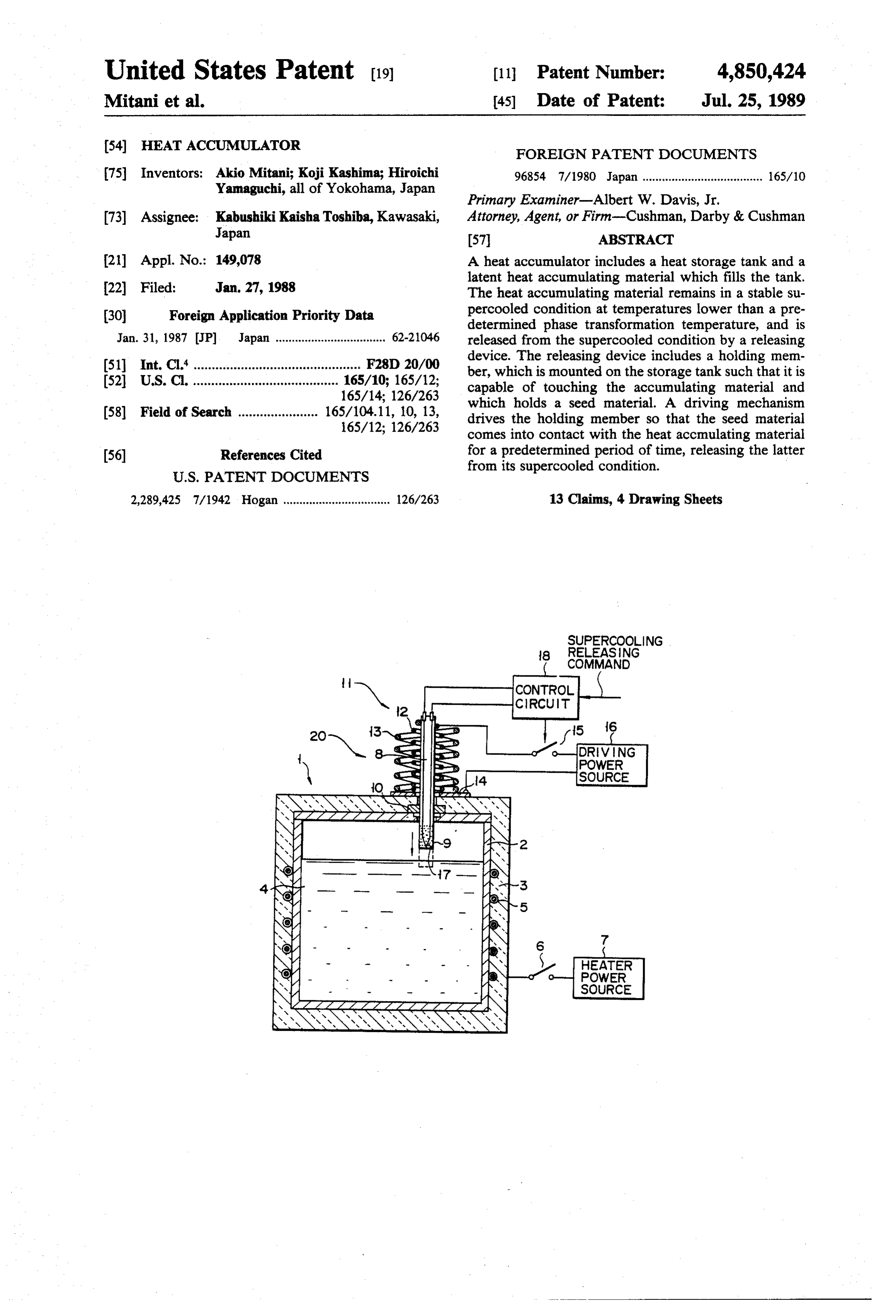
vantage in that they can be constructed in a compact 20 form. BRIEF DESCRIPTION OF THE DRAWINGS A well-known type of latent heat accumulating mate FIGS. 1 through 3 are views and a graph of a heat rial is made of a substance which does not solidify and accumulator according to an embodiment of this inven holds a stable supercooled condition at temperatures tion; in which lower than the phase transformation temperature; for 25 FIG. 1 is a sectional view showing the whole of the example, a sodium acetate-base hydrate. This material heat discharges its latent heat when it is released from super a headaccumulator, portion of a
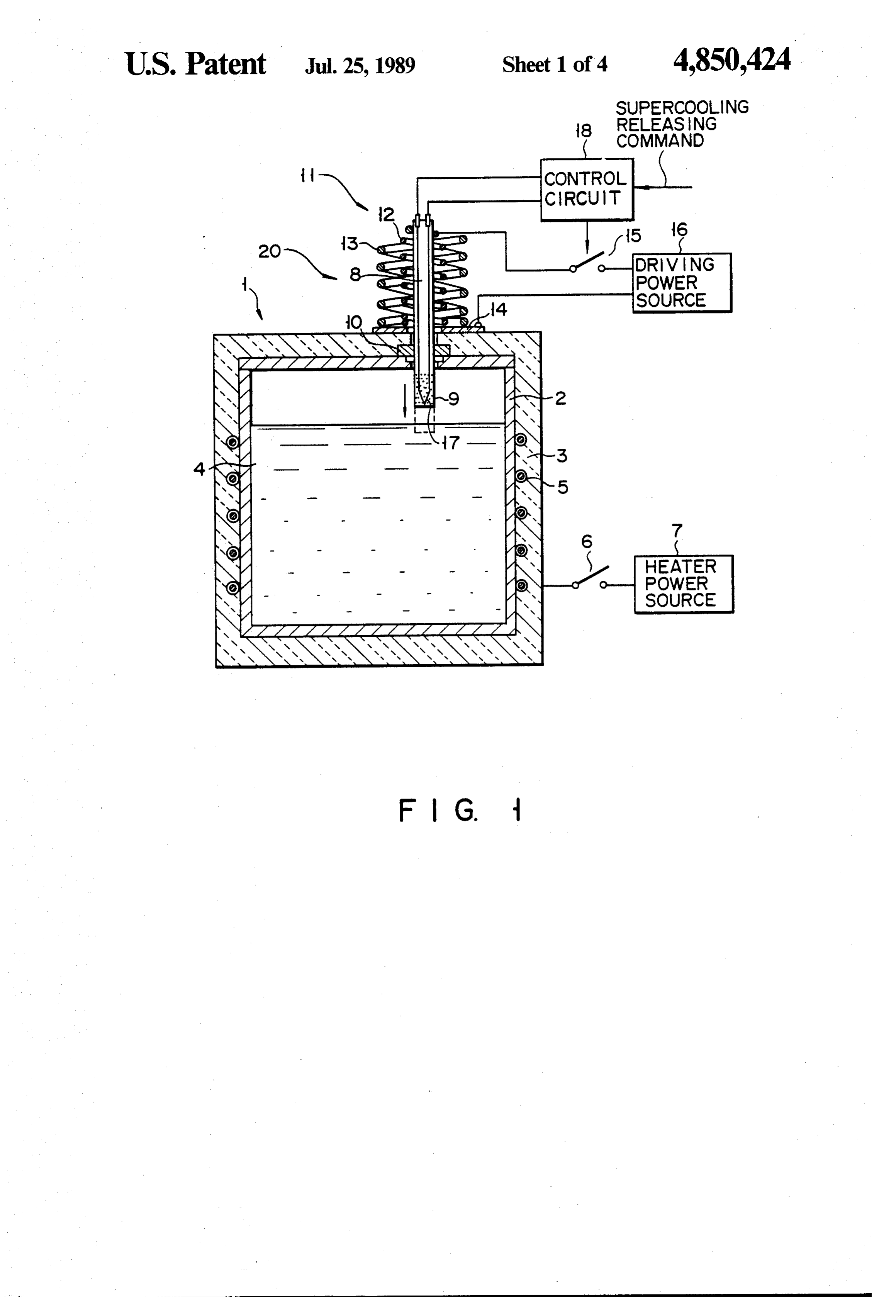
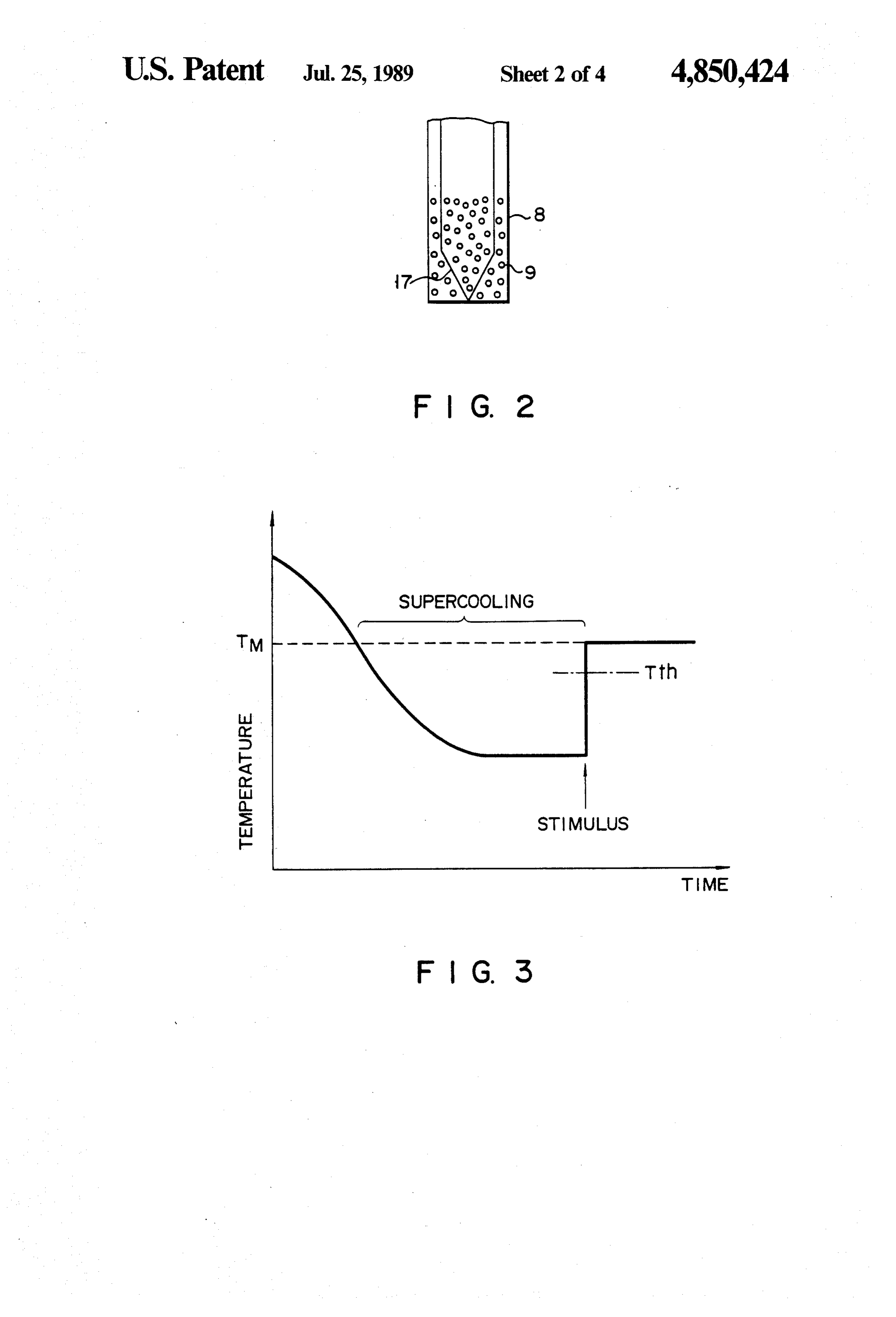
FIG. 2 is an enlarged view showing hold member, and FIG. 3 is a graph cooled condition and transformed from the liquid phase showing the heating and cooling characteristics of a to the solid phase. Using this method, heat energy can latent heat accumulating material; be obtained from this heat accumulating material any 30
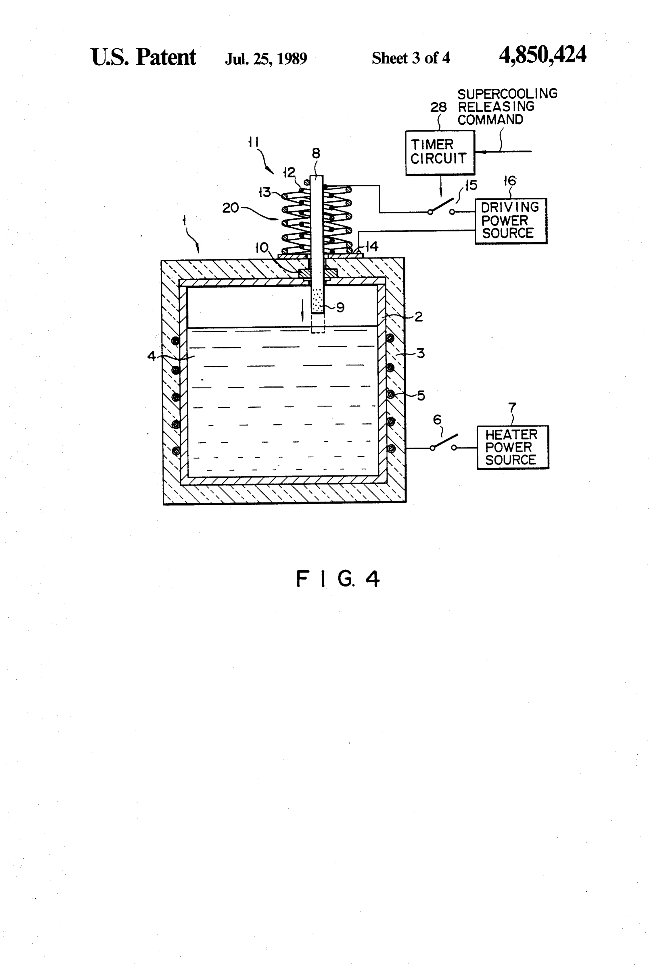
FIG. 4 is a sectional view showing the whole of a time it is required. heat accumulator according to another embodiment of To release this type of latent heat accumulating mate rial from the supercooled condition, all that is normally theFIG.
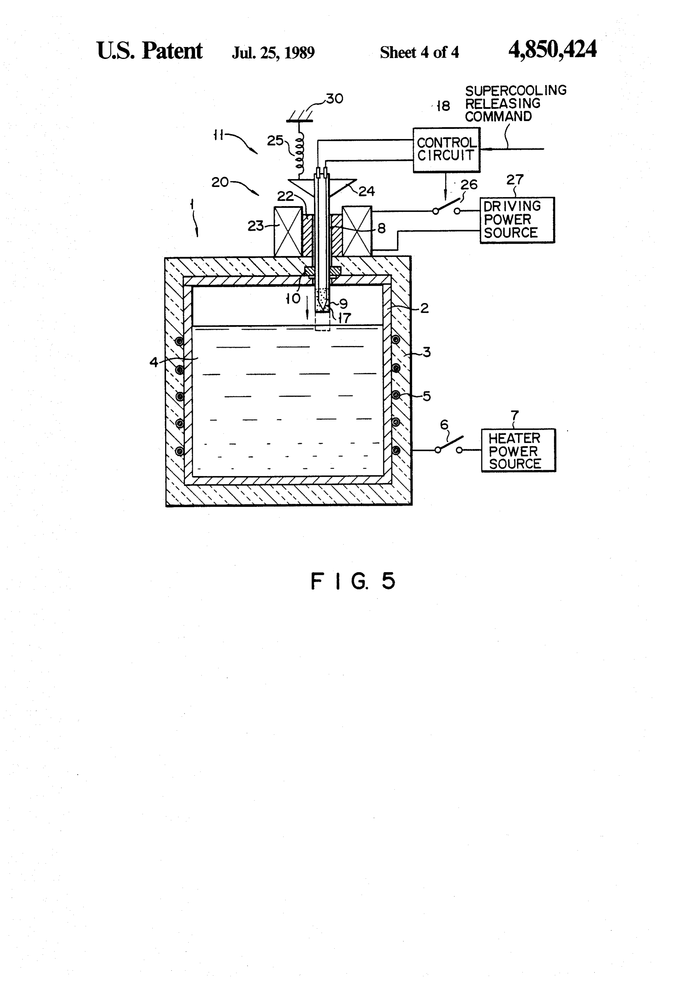
invention; and 5 is a sectional view showing the whole of a necessary is to give an adequate stimulus to the latent heat accumulating material in supercooled condition. 35 mentheat accumulator according to still another embodi These supercooling release methods giving a stimulus of the invention.
include (1) touching the heat accumulating material DETAILED DESCRIPTION OF THE with a sharp metal rod, (2) applying a voltage to the PREFERRED EMBODIMENTS heat accumulating material via an electrode, and (3) Preferred embodiments of this invention will now be adding a seed material to the heat accumulating mate rial. described in detail with reference to the accompanying In the case of methods (1) and (2), however, the form drawings.
ing mechanism of a nucleus necessary for a release from As is shown in FIG. 1, a heat accumulator has heat the supercooled condition has not been fully clarified. storage tank 1 which comprises metal container 2 con In fact, with these methods, the heat accumulating ma 45 taining latent heat accumulating material 4, an electric terial sometimes cannot be released from supercooled heater, e.g., sheath heater 5, wound around the metal condition even if it is given a stimulus and therefore, container, for heating accumulating material 4, and heat they lack reliability. insulating vessel 3 surrounding the outer surface of On the other hand, method (3), which adds a nucleus container 2 and heater 5. Heater 5 is connected through necessary for the termination of supercooling, does 50 switch 6 to heater power source 7. A practical example ensure certain release from the supercooled condition. of latent heat accumulating material is a solution of However, the seed material added to the heat accumu sodium acetate tri-hydrate with 1-2% of xanthan gum lating material gradually accumulates therein, and even added as a thickener.
tually causes a separation of its phases, with the result The heat accumulator is equipped with supercooling that the heat accumulating material can no longer re 55 releasing device 20 for releasing accumulating material main in a stable supercooled condition. 4 from supercooled condition by bringing a seed mate As described above, among the conventional super rial into contact with accumulating material 4. Releas cooling releasing methods, those which give a mechani ing device 20 has rod-like holding member 8 holding cal or electrical stimulus lack reliability, while use of seed material 9. Holding member 8 is mounted on heat those which entail addition of a seed material result in 60 storage tank 1 in a manner that it can move perpendicu degradation of the physical properties of the heat accu larly to the liquid surface of heat accumulating material mulating material. 4 and its lower end can come into contact with the heat SUMMARY OF THE INVENTION accumulating material. As is shown in FIGS. 1 and 2, holding member 8 is formed of a porous material, such
The present invention has been conceived in consid 65 as a polymeric material, and holds powdery seed mate eration of the above situation and has as its object to rial 9 (sodium acetate tri-hydrate) in the pores of its provide a heat accumulator the use of which ensures lower end portion. This holding member is formed, for with certainty the releasing of a latent heat accumulat example, by melting a thermoplastic resin, mixing the
Page 7
resin with a powdery seed material, and Solidifying the dipped about 1 to 2 mm in heat accumulating material 4. mixture. Provided between holding member 8 and heat As a result, seed material 9 held at the lower end portion storage tank 1 is seal 10 which seals off the inside of the of holding member 8 comes into contact with heat accu heat storage tank airtightly. mulating material 4, and the touched part of the heat In holding member 8, there is provided temperature 5 accumulating material is immediately released from the sensor 17 as a detecting means for detecting a contact of supercooled condition, thus beginning to solidify. At the holding member with heat accumulating material 4. the same time, the release from supercooling propagates Sensor 17 consists of a thermocouple, one end extends from the part touched by seed material 9 to the whole of to the lower end of holding member 8 and the other end heat accumulating material 4. When solidifying, heat protrudes outside from the upper end of the holding O accumulating material 4 radiates the latent heat which member and is connected through a lead wire to control has been stored therein.
circuit 18. As heat accumulating material 4 radiates the latent Supercooling releasing device 20 has driving means heat, for driving holding member 8 vertically. This driving placeditsin holding temperature rises. Temperature sensor 17 member 8 detects a temperature rise means includes bias spring 13 and another spring 12 15 of heat accumulating material 4 and outputs a detection which is made of a shape memory alloy. The upper ends signal to control circuit 18. According to a detection of springs 12 and 13 are fixed to holding member 8. The signal from sensor 17, control circuit 18 finds that seed lower end of spring 12 is in contact with and fixed to material 9 is in contact with heat accumulating material electrode 14 secured to the upper surface of heat stor 4. More specifically, as is shown in FIG. 3, when heat age tank 1, and the lower end of bias spring 13 is fixed 20 accumulating directly to the upper surface of tank 1. The upper end of condition by thematerial 4 is released from supercooled spring 12 is connected through switch 15 to one end of lus, the temperature of with contact heat seed material 9 as a stimu accumulating material 4 driving power source 16 and the lower end is connected rises and reaches the phase transformation temperature through electrode 14 to the other end of driving power TM. Control circuit 18 finds that seed material 9 has source 16. Switch 15 is under on-off control by control 25 touched heat accumulating material 4 based on the fact circuit 18,
Latent head accumulating material 4 filled in heat that the temperature detected by sensor 17 exceeds a specified temperature Tth lower than the phase trans storage tank 1 has the heating and cooling characteris formation temperature TM.
tics as indicated in FIG. 3. Heat accumulating material 4 becomes liquid when it is heated to a temperature 30 On finding seed material 9's touching heat accumulat above the phase transformation temperature (melting ing material 4, control circuit 18 turns off switch 15 to point) TM (about 59 C.). However, when the heat accu stop power supply to spring 12. Therefore, spring 12 decreases in temperature. When the shape memory mulating material is cooled from the molten state to a temperature below TM, it does not solidify even though effect of spring 12 goes off, spring 12 is caused to extend its temperature falls and passes the TM point and holds 35 by the urging force of spring 13. At the same time, a stable liquid state, that is, the supercooled condition holding member 8 is moved upward and thus separated until a temperature below TM, -10° C. for example, is from heat accumulating material 4.
reached. When supercooled heat accumulating material With the heat accumulator constructed as described 4 is given a stimulus by contact with seed material 9 above, the supercooled condition of the heat accumulat which will be described later, the part in contact with ing material is terminated by bringing seed material 9 the seed material is released from the supercooled con held by holding member 8 into contact with heat accu dition and the release from supercooled condition prop mulating material 4. This heat accumulator has ex agates to the whole body of the heat accumulating ma tremely high reliability compared with those heat accu terial. Consequently, heat accumulating material 4 radi mulators which terminates supercooling by a mechani ates heat. 45 cal or electrical stimulus. In this heat accumulator, Seed The operation of the thus constructed heat accumula material 9 to touch heat accumulating material 4 is held tor will be described. by holding member 8, so that it is possible to prevent the When heat accumulating material 4 is solid, it is problem that the heat accumulating material is deterio heated through container 2 to a temperature above the rated by the addition and accumulation of the seed phase transformation temperature TM by closing switch 50 material in the heat accumulating material. Further, 6 and supplying power to heater 5 or by some sort of holding member 8 is so constructed that it is withdrawn waste heat. As a result, heat accumulating material 4 from the heat accumulating material immediately after becomes liquid. Then, heat accumulating material 4 is material 4 is released from the supercooled condition. left to stand and cooled by the atmospheric air through Hence, even when heat accumulating material 4 solidi heat insulating layer 3. However, heat accumulating 55 fies quickly after the termination of supercooling, there material 4 is held by the effect of heat insulating layer 3 is no possibility that holding member 8 is arrested by the at a temperature higher than the critical supercooling heat accumulating material and the holding member can temperature. Therefore, heat accumulating material 4 is be pulled out smoothly. This makes it possible to pre supercooled and holds latent heat. vent seed material 9 itself and the heat accumulating When the latent heat stored in heat accumulating 60 material from deteriorating by the melting of seed mate material 4 is used, a supercooling releasing command is rial 9 by the heat radiated from heat accumulating mate given to control circuit 18. Then, control circuit 18 rial 4, resulting from the termination of supercooling. turns on switch 15 so as to cause driving power source Also, it is possible to prevent another problem that the 16 to supply power to spring 12, thereby heating the adhesion of the thickener in heat accumulating material spring. When being heated to a temperature above a 65 4 to seed material 9 impairs the stimulating action of the specified transformation temperature, spring 12 starts to seed material, that is to say, the seed material cannot contract by its shape memory effect. Consequently, touch the heat accumulating material. Therefore, it is holding member 8 lowers and its lower end portion is possible to subject the heat accumulating material to
Page 8
repeated execution of supercooling and its release over a piece containing a seed material may be fixed to the an extended period of time. head of the holding material.
In the above embodiment, driving power source 16 is Further, means for detecting the seed material's used to energize spring 12. A voltage of about 1.2V will contact with the heat accumulating material need not be suffice. An advantage resulting from this is that driving 5 a temperature sensor, but may be a pressure sensor. The power source 16 may be small and therefore, the whole contact detecting means has only to touch the heat unit of heat accumulator can be compact in size. accumulating material and may be mounted on the sur FIG. 4 shows a second embodiment of this invention. face of the holding member. In the third embodiment, In this embodiment, temperature sensor 17 used in the the control circuit may be replaced by a timer circuit first embodiment described above is excepted and timer 10 and the temperature sensor may be removed as in the circuit 28 is used in place of control circuit 18. Another second embodiment.
construction is the same as in the first embodiment and What is claimed is:
its detailed description will be omitted. 1. A heat accumulator comprising: According to the second embodiment of this inven a heat storage tank;
tion, when receiving a supercooling releasing com 15 a latent heat accumulating material filling the heat mand, timer circuit 28 keeps switch 15 turned on for a storage tank and capable of remaining in a stable given period of time and energizes spring 12 only for supercooled condition at temperatures lower than this period. Therefore, if a desired operation time of a specified phase transformation temperature; and timer circuit is selected, seed material 9 can be pulled releasing means for releasing the latent heat accumu automatically out of heat accumulating material 4 after 20 lating material from supercooled condition, the allowing the seed material to touch the heat accumulat releasing means having a holding member mounted ing material for a period of time necessary for releasing on said heat storage tank in a manner such as to be the heat accumulating material from the supercooled capable of touching said latent heat accumulating condition. This means that contact detecting means material, a seed material made of the same type of such as a temperature sensor is not necessary and the 25 material as said latent heat accumulating material manufacturing cost of heat accumulators can be re and held by said holding member, and driving duced. means for automatically moving said holding mem FIG. 5 shows a third embodiment of this invention. ber to bring the seed material into contact with said In this embodiment, driving means 11 for moving hold heat accumulating material for a predetermined ing member 8 differs in construction from that of the 30 period of time and automatically moving said hold first embodiment. That is to say, holding member 8 is ing member to separate said seed material from said inserted in tubular guide 22 secured to the top surface of heat accumulating material. heat storage tank 1, and the holding member moves 2. A heat accumulator according to claim 1, wherein vertically with being guided by this tubular guide. An said holder member is mounted on the heat storage tank nular electromagnet 23 is attached to the outer periph 35 to be movable in a direction almost perpendicular to the ery of tubular guide 22 and connected through switch liquid surface of the heat accumulating material, the 26 to driving power source 27. Fixed to the upper end holding member having a head part capable of touching portion of holding member 8 is magnetic piece 24 which the heat accumulating material, said head part holding is opposed to electromagnet 23. Magnetic piece 24 the seed material.
should preferably be a permanent magnet. Magnetic 40 3. A heat accumulator according to claim 2, wherein piece 24 is connected through return spring 25 to sup said holding member is formed of a porous material, and port 30. the seed material is held in a plurality of pores formed in In the third embodiment constructed as described the holding member.
above, when heat accumulating material 4 is released 4. A heat accumulator according to claim 2, wherein from the supercooled condition, control circuit 18 turns 45 said driving means includes a first urging member cou on switch 26 so that power is supplied to electromagnet pled to the holding member, for urging the holding 23 from driving power source 27. Hence, magnetic member to a no-contact position where the seed mate piece 24 is attracted by electromagnet 23 and moves rial is separated from the heat accumulating material, a downward with holding member 8. As a result, seed second urging member coupled to the holding member material 9 held by the lower end portion of holding 50 and formed of a shape memory alloy, for urging the member 8 touches heat accumulating member 4, thus holding member to a contact position where the seed releasing the heat accumulating material from the su material touches the heat accumulating material when percooled condition. As in the first embodiment, ac heated, heating means for heating the second urging cording to a detection result by temperature sensor 17, member, and a control circuit for controlling the opera control circuit 18 turns off switch 26, with the result 55 tion of the heating means.
that power supply to electromagnet 23 is stopped. Con 5. A heat accumulator according to claim 4, wherein sequently, holding member 8 and magnetic piece 24 are said heating means has a driving power source for sup raised by return spring 25. plying power to the second urging member. With the second embodiment constructed as set forth 6. A heat accumulator according to claim 4, wherein above, the same effect as in the first embodiment can be said driving means has contact detecting means for obtained. detecting contact between the seed material and the It is understood that the present invention is not lim heat accumulating material, and the control circuit ited to the above preferred embodiments, and that vari stops the operation of the heating means according to a ous changes and modifications may be effected therein detection signal from the contact detecting means. by one skilled in the art within the scope of this inven 65 7. A heat accumulator according to claim 6, wherein tion. said contact detecting means has a temperature sensor To take an example, the holding member and the seed for detecting the temperature of the heat accumulating material need not be formed in an integrated body, but material.
Page 9
8. A heat accumulator according to claim 4, wherein 12. A heat accumulator according to claim 4, wherein said control circuit has a timer for stopping the opera said control circuit has a timer for stopping the opera tion of the heating means after passage of a specified tion of the heating means after passage of a specified time from when the heating means starts to operate. time from when the heating means starts to operate. 9. A heat accumulator according to claim 2, wherein 5 13. A heat accumulator comprising: said driving means comprises an urging member cou a heat storage tank;
pled to the holding member, for urging the holding a latent heat accumulating material filling the heat member to a no-contact position where the seed mate storage tank and capable of remaining in a stable rial is separated from the heat accumulating material, a supercooled condition at temperatures lower than magnetic piece secured to the holding member, an elec 10 a specified phase transformation temperature; and tromagnet which, when energized, attracts the mag releasing means for releasing the latent accumulating netic piece, thereby moving the holding member to a material from a supercooled condition, the releas contact position where the seed material touches the ing means having a seed material made of the same heat accumulating material, a power applying means for type of material as the latent heat accumulating energizing the electromagnet, and a control circuit for 15 material, a holding member holding the seed mate controlling the operation of the power applying means. rial and supported by the heat storage tank to be 10. A heat accumulator according to claim 9, wherein movable between a contact position where the seed said driving means has contact detecting means for material touches the heat accumulating material detecting contact between the seed material and the and a no-contact position where the seed material is heat accumulating material, and the control circuit 20 separated from the heat accumulating material and stops the operation of the power applying means ac drive means including first moving means for mov cording to a detection signal from the contact detecting ing the holding number to the contact position, and e3S. second moving means for moving the holding 11. A heat accumulator according to claim 10, member to the non-contact position, and means for wherein said contact detecting means has a temperature 25 actuating first moving means and then actuating sensor for detecting the temperature of the heat accu the second moving means.
mulating material. k : x: k ck
Provenance
- Collection
- Cited prior art
- Original PDF
- patentimages.storage.googleapis.com →
- Filed
- 1988-01-27
- Pages
- 9
- Method
- pdftotext (the PDF's own text layer) + pdftoppm 300dpi page scans
- Source
- Google Patents bibliographic record
- Granted
- 1989-07-25
- Inventors
- Akio Mitani; Koji Kashima; Hiroichi Yamaguchi; Toshiba Corp
- Transcribed from
- patentimages.storage.googleapis.com →