patent · US1401035
Gas-generator
20 December 1921
Page 1
Drawing sheet — no readable text.
Page 2
MARTIN BOISEN, OF SANDUSKY, cHo.
401,03 Specification of letters eatent, Paterated Dec. 20, 1921. Application filed March 19, 1921. Serial No. 453,648.
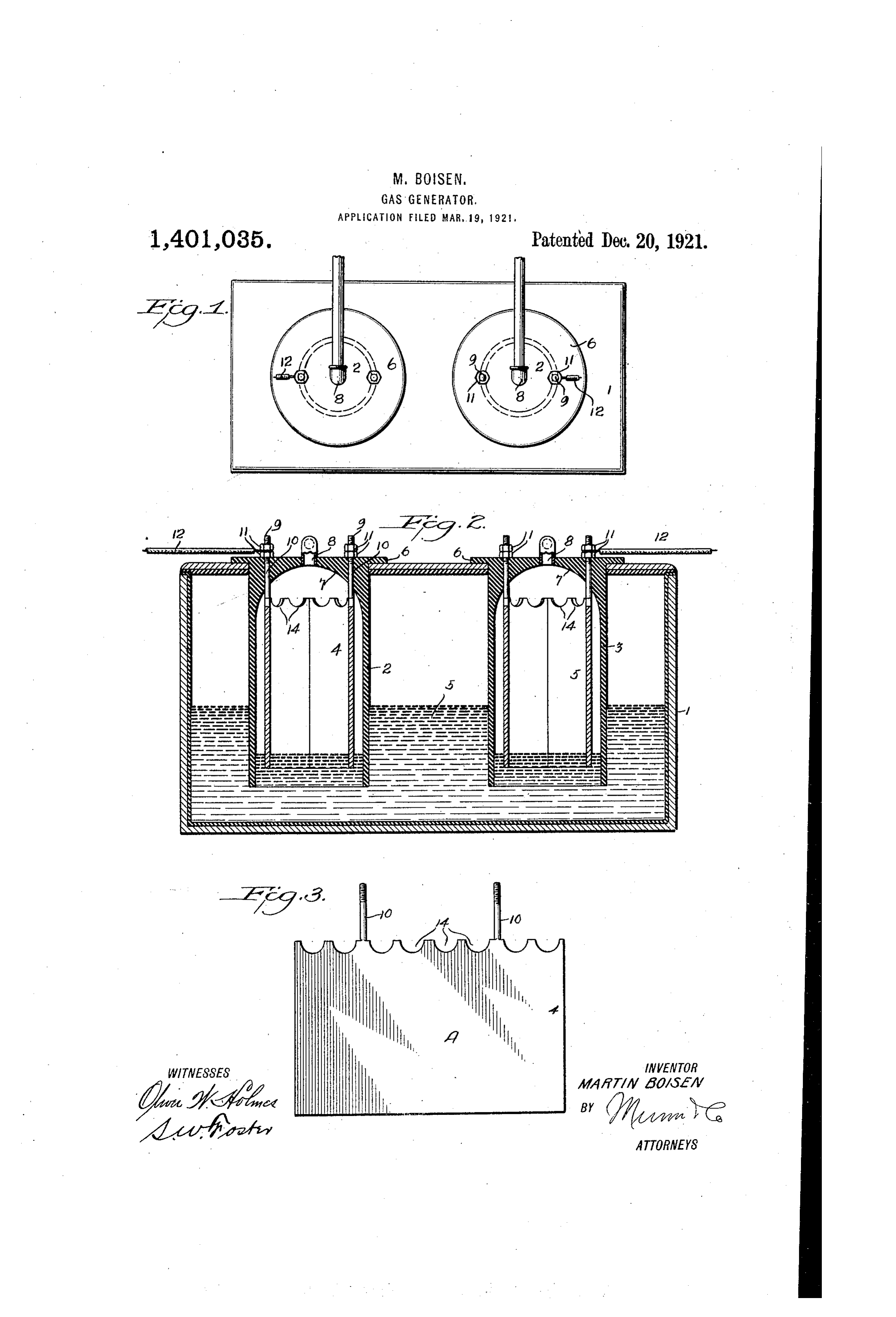
To all whom it; may concern. points of the cells so that the gases will nat Be it known that , MARTIN BoISEN, a cit urally flow into said outlets. izen of the United States, and a resident of The electrodes 4 and 5 are hollow or tu Sandusky, in the county of Erie and State bular in form and may be cylindrical or 60 of Ohio, have invented a new and improved other shape. These electrodes have each a Gas-Generator, of which the following is a pair of upwardly projecting binding posts full clear, and exact description. 9, which project through openings 10 in the This invention relates to improvements in cells 2 and 3 and are provided with nuts 11 gas generators, an object of the invention for securing electric wires 12 to the binding 10. being to provide an improved construction posts. ". and arrangement of apparatus for electri These binding posts are cemented or oth cally decomposing water to generate oxygen erwise secured in the openings 10 to render and hydrogen and direct these gases through the connection gastight, and it will be noted
Separate outlets to any desired containers that they support the upper ends of the elec 70 5 or point of use. - trodes spaced from the top of the cells, and A further object is to improve upon the said upper ends are preferably recessed or construction of generator disclosed in my corrugated, as shown at 14, to permit any copending application, Serial No. 394,168, gas which may accumulate in the cells and filed July 6, 1920, for improvements in gas outside of the electrodes to flow freely into 75 20 generators. and through the outlets S. With these and other objects in view the The lower ends of the electrodes are invention consists in certain novel features spaced above the lower ends of the cells of construction, and combinations and ar so that when the gas pressure in the cells rangements of parts as will be more fully reaches a predetermined degree. the Water 25 hereinafter described and pointed out in the in the lower ends of the cells will be forced 80 claims. downwardly below the lower ends of the In the accompanying drawings- . electrodes to stop further generation of gas Figure 1 is a top plan view of my im until the pressure is relieved, hence, the proved generator. - pressure of the gas generated is automati 85 30 Fig. 2 is an enlarged view in longitudinal cally maintained at the desired degree. The cells 3 are formed of any suitable in vertical section through the center of the sulating generator. material and the electrodes 4 and Fig. 3 is a plan view of a blank from 5 are preferably of sheet metal formed from which I form my improved electrodes. a blank A, such as indicated in Fig. 3. 35 1 represents my improved decomposing This blank is made with the integral bind 90 tank, in which I support a pair of cells 2 ing posts 9 or the latter may be fixed to and 3 and locate electrodes 4 and 5 in the the blank in any approved manner, and cells 2 and 3 respectively, the electrode 4 the blank is then curved or otherwise shaped constituting an anode and the electrode 5 a. to form a hollow or tubular electrode. 40 cathode, or vice versa. The electrode 4, constituting the anode, 95 The cells 2 are of insulating material of is preferably of nickel or other suitable general cylindrical form having open lower material, upon which oxygen has little or ends submerged in the water 5 in the tank. no effect. The cathode 5 is preferably of The upper ends of the cells 2 have annular aluminum or other suitable material, upon 45 flanges or other projections 6 resting on the which hydrogen has little or no effect. 100 upper face of the tank 1 and the connection. The ratio of the diameters of the elec between the cells and the tank is rendered trodes with relation to the cells, Would be gas tight in any approved manner. governed by both the ratio of the conduc While the upper outer surfaces of the tivity of the substances used as electrodes 50 cathode may or may not be flat as desired, and the ratio of the pressure of the gases 105 the inner surfaces of the upper ends of the on the water in the cells, thereby giving the cells are concave or dome-shaped, as indi same ratio of active surface exposed to the cated at 7, so as to direct the gases in the water at all times. --- -. cells into tubular outlets 8 located in the In using the term “tubular” or “hollow' center of the upper ends at the highest electrode and cell, it is obvious that these 10
Page 3
terms are employed in their broadest sense site sides of each electrode projected through 40 to include any shape of cross-section. the upper ends of the cells and supporting i provide two binding posts 9 on each the electrodes.
electrode not only because these binding 3. A gas generator, comprising a tank posts constitute a iiian support for the elec adapted to contain water, tubular cells of trodes, but in the event, that one of the insulating material suspended in the tank binding posts is broken or injured, the other and having their lower ends Submerged in can be used, and it is, of course, to be under the Water of the tank and having outlets stood that in most cases at least, but a single in their upper ends, and hollow electrodes 0 binding post. On each cathode will be in Supported in the cells and spaced from the electric circuit, with the Source of electricity, walls of the cells and from the upper ends 50 Various slight changes alight be made in of the cells, said cells having internally the generai form and arrangeinent of the concave or dome-shaped upper ends with parts described without, departing froxi the the outlets at the centers of the upper ends 15 invention, and hence i do :08, initiayself of4.theA cells. gas generator, coinprising a tank to the precise details set, forth, but consider myself at liberty to make Such changesSpirit and adapted to contain water, tubular celis of 5 5 alterations as fairly fall within the insulating material suspended in the tank and Scope of the appended claims. and having their lower ends submerged in 20 claim: - the water of the tank and having outlets i. A gas generator, comprising a tank in their tipper ends, hollow electrodes sup 60 adapted to contain water, tubular ceils of of ported in the cells and Spaced from the wails the cells and from the upper ends of insulating material suspended in and having their lower ends Stiki the cells, said cells having internally con the water of the tank and having 25 in their upper ends, and hollow electrodes outletscave or dome-shaped upper ends with the at the centers of the upper ends supported in the cells, spaced from the of the cells, and said electrodes having ser walls of the cells and from the upper ends rated upper ends.
5. A gas generator, comprising a tank,
30 2. A gas generator, comprising a tank cells in the tank, hollow electrode in the adapted to contain water, tubular cells of cells, said electrodes formed of sheet metal insulating material suspended in the tank blanks bent into tubular form, and bind 70 and having their lower ends submerged in ing posts fixed to the upper ends of the the water of the tank and having outlets electrodes and projected through openings 35 in their upper ends, hollow electrodes sup in the upper ends of the celis, said cells hav ported in the cells and spaced from the walls ing gas outlets in their upper ends. of the cells and from the upper ends of the cells, and a pair of binding posts on oppo MARTIN BOISEN.
Provenance
- Collection
- Cited prior art
- Original PDF
- patentimages.storage.googleapis.com →
- Filed
- 1921-03-19
- Pages
- 3
- Method
- pdftotext (the PDF's own text layer) + pdftoppm 300dpi page scans
- Source
- Google Patents bibliographic record
- Granted
- 1921-12-20
- Inventors
- Boisen Martin
- Transcribed from
- patentimages.storage.googleapis.com →