patent · US4416224
Internal combustion engine
22 November 1983
Page 1 — bibliographic record
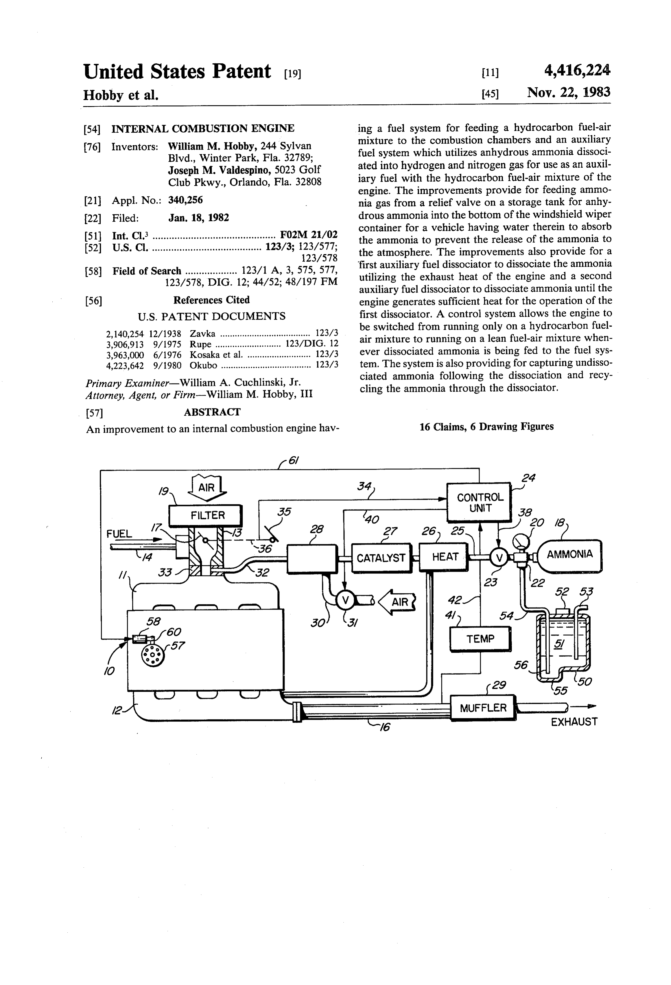
United States Patent (19) 11) 4,416,224 Hobby et al. 45) Nov. 22, 1983 54 INTERNAL COMBUSTION ENGINE ing a fuel system for feeding a hydrocarbon fuel-air mixture to the combustion chambers and an auxiliary 76) Inventors: William M. Hobby, 244 Sylvan fuel system which utilizes anhydrous ammonia dissoci Blvd., Winter Park, Fla. 32789; ated into hydrogen and nitrogen gas for use as an auxil Joseph M. Valdespino, 5023 Golf
Club Pkwy., Orlando, Fla. 32808 iary fuel with the hydrocarbon fuel-air mixture of the engine. The improvements provide for feeding ammo 21 Appl. No.: 340,256 nia gas from a relief valve on a storage tank for anhy 22 Filed: Jan. 18, 1982 drous ammonia into the bottom of the windshield wiper container for a vehicle having water therein to absorb 51 Int. Cl. ............................................. F02M 21/02 the ammonia to prevent the release of the ammonia to 52 U.S. Cl. ........................................ 123/3; 123/577; the atmosphere. The improvements also provide for a
58) Field of Search ................... 123/1 A, 3, 575, 577, first auxiliary fuel dissociator to dissociate the ammonia 123/578, DIG. 12; 44/52; 48/197 FM utilizing the exhaust heat of the engine and a second auxiliary fuel dissociator to dissociate ammonia until the 56) References Cited engine generates sufficient heat for the operation of the
2,140,254 12/1938 Zavka ..................................... 123/3 be switched from running only on a hydrocarbon fuel 3,906,913 9/1975 Rupe ...... ... 123/DIG. 12 air mixture to running on a lean fuel-air mixture when 3,963,000 6/1976 Kosaka et al. ... 123/3 ever dissociated ammonia is being fed to the fuel sys 4,223,642 9/1980 Okubo ..................................... 123/3 tem. The system is also providing for capturing undisso Primary Examiner-William A. Cuchlinski, Jr. ciated ammonia following the dissociation and recy Attorney, Agent, or Firm-William M. Hobby, III cling the ammonia through the dissociator.
An improvement to an internal combustion engine hav 16 Claims, 6 Drawing Figures
CONTROL
UNIT
Page 2
Drawing sheet — no readable text.
Page 3
Drawing sheet — no readable text.
Page 4
the conventionally fueled engine can be run very lean,
INTERNAL COMBUSTION ENGINE well below where the engine would normally misfire as the engine approaches the flammability limit of the fuel.
BACKGROUND OF THE INVENTION The normal flammability limit for hydrogen fuel-air 1. Field of the Invention mixtures occurs with a relatively high NOx formation The present invention relates to internal combustion rate and thereby imposes severe limitations on the lean engines and especially to improvements in internal com limit operation for the fuel. Since hydrogen exhibits a bustion engines having an auxiliary ammonia gas feed flammability limit well below that of conventional hy metering gas through a dissociation system into the drocarbon fuels, it is possible to reduce the NO simply combustion chambers along with the normal hydrocar 10 by using the hydrogen to change the fuel-air mixture to bon fuel-air mixture of the engine while leaning the a much lenaer mixture than would normally be allowed. engine below its normal operating fuel-air mixture. This The extension of the misfire limit to very lean equiva invention is an improvement over the invention in my lence ratios with hydrogen fuel also yields significant co-pending U.S. patent application for an Internal Com 15 increases in the thermodynamic efficiency of the com bustion Engine, Ser. No. 164,038, filed on June 30, 1980 bustion process, thereby allowing a substantial increase now abandoned. in the mileage obtained on a conventional internal com 2. Description of the Priot Art bustion fueled engine vehicle.
In the past, a variety of internal combustion engines The difficulties in using hydrogen either as the sole have been provided and typically these engines have a 20 fuel or in combination with a conventional internal system for feeding a hydrocarbon fuel, such as gasoline mixed with air into the combustion chamber for running combustion engine results from the hydrogen being a ubiquitous and very flammable gas, so that storage in the engine. Such engines typically also have an electri creases cal system which includes a generator or an alternator general the hazards of operating the engine and in the which may be connected through an electrical regulat 25 throughinefficiency electrolysis in generating the hydrogen such as on the vehicle.
ing circuit for charging a storage battery and for operat The present invention is directed toward the use of an ing the electrical components of the engine of the vehi ammonia gas used in combination with a conventional cle. Internal combustion engines sometimes have hy hydrocarbon fuel-air mixture to increase the efficiency drocarbon fuels mixed with air in a carburetor where the mixture is distributed into the combustion chambers of the engine and to reduce pollution in the engine. of the engine. It is also typical to feed the air to the 30 Ammonia has been mentioned as a constitutent of vari combustion chambers using a fuel injection system for ous types of fuels in the past, both for internal combus injecting fuel directly into the combustion chambers. tion engines and for jet propulsion. One such fuel is a The present invention can be adapted to operate with liquid mixture of ammonious nitrate in liquid ammonia either a carburetor or fuel injection system. which is a self-sustaining fuel combination requiring no A variety of hydrogen fueled engines have been sug 35 addition of an oxident such as air. Ammonia is also used gested in the past, including those using combinations of to manufacture hydrozene, a well known rocket fuel, hydrogen and oxygen, which in some cases are gener and while ammonia does not support combustion, it will ated in an electrolytic cell having an electrolyte includ burn when mixed with oxygen in air to give a variety of ing solutions of salts, acids or bases in water. The elec products, principally nitrogen and water. Mixtures of trolytic cell breaks the water down between hydrogen 40 nitrous oxide and ammonia in a rate of 3 to 2 will deto and oxygen through electrolysis and the hydrogen or nate with some violence yielding nitrogen and water. the hydrogen and oxygen in combination can then be One prior U.S. patent showing the use of ammonia as used to run the engine. The advantage of the hydrogen constituent in fuel for internal combustion engines can and oxygen as fuel is that it is an efficient fuel which be seen in the Drouilly U.S. Pat. No. 2,559,605, for a generates no pollution in that the combustion forms 45 fuel mixture for internal combustion engines. In this water in very minute quantities. Such engines, however, patent, ammonia gas is fed from one storage cylinder have not been brought into general use because of the into a pressure reducing chamber and a second bottle inefficiency in the generation of hydrogen and oxygen through electrolysis which takes far more power than containing ing gas, is an auxiliary gas, such as ethanized illuminat fed into a second expansion chamber and the can be generated from the hydrogen and oxygen used as 50 two gases are then fed into a mixing chamber, and from a fuel, even in high efficiency engines. the mixing chamber into a carburetor. This patent also It has also been suggested to use small amounts of discusses the use of carbomonoxide, methyl ether, ethyl hydrogen added to the hydrocarbon fuel-air mixture to ether, methyl amine and ethyl amine increase the efficiency or reduce the pollution of the with ammonia. In the patent to Meyer,inU.S. combination internal combustion engine. One prior patent, U.S. Pat. 1,671,158, a fuel for use in internal combustionPat. 55 No.
engines
No. 3,906,913, discusses in detail the advantages of the consists of a mixture of hydrocarbon distillates with use of small amounts of hydrogen with the hydrocarbon ether and a highly volatile basic material, which may be fuel-air mixture of a vehicle and points out that the advantages of reduced pollution and increased mileage ammonia. The mixture can then be used in internal combustion engines according to the patent. The patent result from running the engine much leaner than can to Brooks, U.S.
Pat. No. 1,748,507, shows a process of otherwise be accomplished because the misfire limit for reducing stable hydrocarbon oils in which ammonia or hydrocarbon fuels can be well exceeded. The carbon monoxide and NOx (oxides of nitrogen) emissions have certain alkaline compounds are mixed with light hydro carbon oils to prevent discoloration and sedimentation.
been found to decrease as the fuel-air ratio is made leaner and if the fuel-air ratio can be made sufficiently 65 In two of these U.S. patents, ammonia is used in small lean, it can be made substantially free of CO and NOx. amounts in a fuel mixture, which may then be used as a This patent shows a hydrogen generator and means to fuel in an internal combustion egine; while in the control the feed of the hydrogen to the engine so that Drouilly patent, expanded ammonia gas is mixed with
Page 5
another gas to form a gaseous fuel mixture for running valve for relieving excessive pressure in the tank by an internal combustion engine. releasing small amounts of auxiliary fuel therefrom. A Other prior U.S. patents utilizing ammonia as a fuel container, such as the windshield washer container of a include U.S. Pat. No. 3,150,645 which uses a method of vehicle, which is partially filled with a material, such as operating a compression ignition engine using ammonia 5 water, adapted to absorb the auxiliary fuel, is mounted as the primary fuel; U.S. Pat. No. 1,384,946 for a com ajdacent the internal combustion engine. A coupling posite motor fuel which uses reagents admixed with the fuel to neutralize or destory the corrosive products of line connects the pressure relief valve into the bottom explosive combustion in the engine cylinders, which the reliefofvalve portion the container so that escaping gas through will be absorbed in the material in the include among other reagents, ammonia. In U.S. Pat. 10 container rather than released into the atmosphere. In No. 4,223,642, a small amount of ammonia gas is ob the case of a windshield washer container, the coupling tained from ammonia bicarbonate or ammonia carbon ate for use in the internal combustion engine. In U.S. extends withdrawn to below the lowest level at which water is from the container so that the end of the
Pat. No. 2, 140,254 to Zafka, an internal combustion engine is operated on ammonia as a fuel by dissociating 15 tube is always covered with water. The engine is also a small portion of the ammonia into hydrogen and nitro improved by having a first auxiliary fuel dissociation gen, utilizing exhaust heat, and then adding the dissoci system for dissociating the auxiliary fuel, such as ammo ated gas back into the ammonia gas to run the engine. nia, into hydrogen and nitrogen, and feeding the disso The hydrogen apparently extends the flammability lim ciated fuel into the internal combustion engine when the its of the ammonia so that it can be used as a fuel. Am- 20 engine has sufficient heat from the engine waste heat to monia, however, has only about half the btu value per dissociate the auxiliary fuel and a control system allows pound as gasoline, and therefore, by itself is not consid a second auxiliary fuel dissociator to be cut out when ered an efficient fuel. In addition, its narrow flammabil sufficient heat has built up in the first auxiliary fuel ity range makes it difficult to use as a fuel. dissociator for dissociating ammonia. Other prior art patents can be seen in U.S. Pat. Nos. 25 The second auxiliary fuel dissociator can use an elec 4,036,180 and 4,230,072, both to Noguchi, et al., for fuel tric heater with a catalyst, or alternatively, can use a reforming systems for internal combustion engines re silent electrical discharge through the ammonia gas for forming methanol; and in U.S. Pat. No. 1,899,869 for a dissociating the gas until the primary dissociator re gas engine; U.S. Pat. No. 4,054,423 for a variable pres ceives sufficient heat. The second auxiliary fuel dis sure fuel generator and method; and in U.S. Pat. Nos. 30 sociator allows the engine to be run lean at all times
The advantage in using ammonia in the present inven without having to switch from a lean to a normal engine and back during engine warm-up.
tion is that ammonia is useful as a convenient means for transporting small volumes of hydrogen since the gas A control system can be provided for controlling the obtained by decomposition contain 75% by volume of 35 internal combustion engine using an auxiliary fuel hydrogen and 25% by volume of nitrogen. The ammo which is dissociated to provide a source of hydrogen for nia is easily liquefied either by cooling to below its use with the hydrocarbon fuel-air mixture, which can normal boiling point of -33.42 C. or by compression include an auxiliary feed control for controlling the and can be stored in a liquid state in small compression auxiliary fuel initiation upon reaching a predetermined cylinders. Ammonia can be thermally dissociated in the 40 temperature in the ammonia dissociator and can include presence of certain catalysts to give nitrogen and hy a system for automatically shifting the engine to a lean drogen and dissociation can also be affected by photo burning engine at the same time hydrogen is added to chemical means or by passing an electrical discharge the fuel-air mixture of the engine and to simultaneously through the gas. Ammonia can be obtained a number of advance the spark for operating the engine under lean ways, but is normally prepared synthetically by a modi- 45 conditions. The controls can also vary the auxiliary fuel fication of the Haber process using pressures between feed with engine conditions and with variations in the 200 and 1,000 atmospheres and temperatures between hydrocarbon fuel feed and may provide a switch for 400 and 500 C. along with a variety of catalysts. The switching the auxiliary ammonia dissociator in and out present invention advantageously can be adapted as an in accordance with temperature conditions and for dis add-on to existing hydrocarbon fueled internal combus tion engines, as well as designed for new vehicles and abling shift a vacuum modulator in a closed loop system to the carburetor to its maximum lean position.
allows a substantial increase in the mileage obtained The engine is also improved with a gas separation from the hydrocarbon fuels and a reduction of at least means connected between the fuel dissociator and the certain pollutants in the exhaust of a vehicle and since the dissociated ammonia is metered in accordance with 55 engine to recover undissociated ammonia from the the requirements of the engine and the leaning of the combined ammonia, hydrogen and nitrogen and feeding engine can be similarly controlled, the efficiency can be the ammonia back to the catalytic dissociator to prevent easily optimized for any particular internal combustion the engine from burning ammonia. The gas separator engine. can use a divided container for bubbling the gas through water which absorbs the ammonia in the mixture while
SUMMARY OF THE INVENTION 60 allowing the hydrogen to be fed to the engine. The An improvement in an internal combustion engine ammonia captured in the water is released by heating it which has an auxiliary fuel system for feeding an auxil from the second part of the divided container where the iary fuel stored under pressure to the engine includes gas is captured and fed back into the front portion of the the following improvements. 65 catalytic dissociator. Cooling fins on the ammonia cap A pressure tank for holding an auxiliary fuel, such as turing side of the container maintains the water cooled anhydrous ammonia, under pressure is juxtaposed adja than on the removing side where the ammonia is being cent an internal combustion engine and has a relief separated from the water.

Page 6
be iron and nickel and may include osmium, zinc, ura
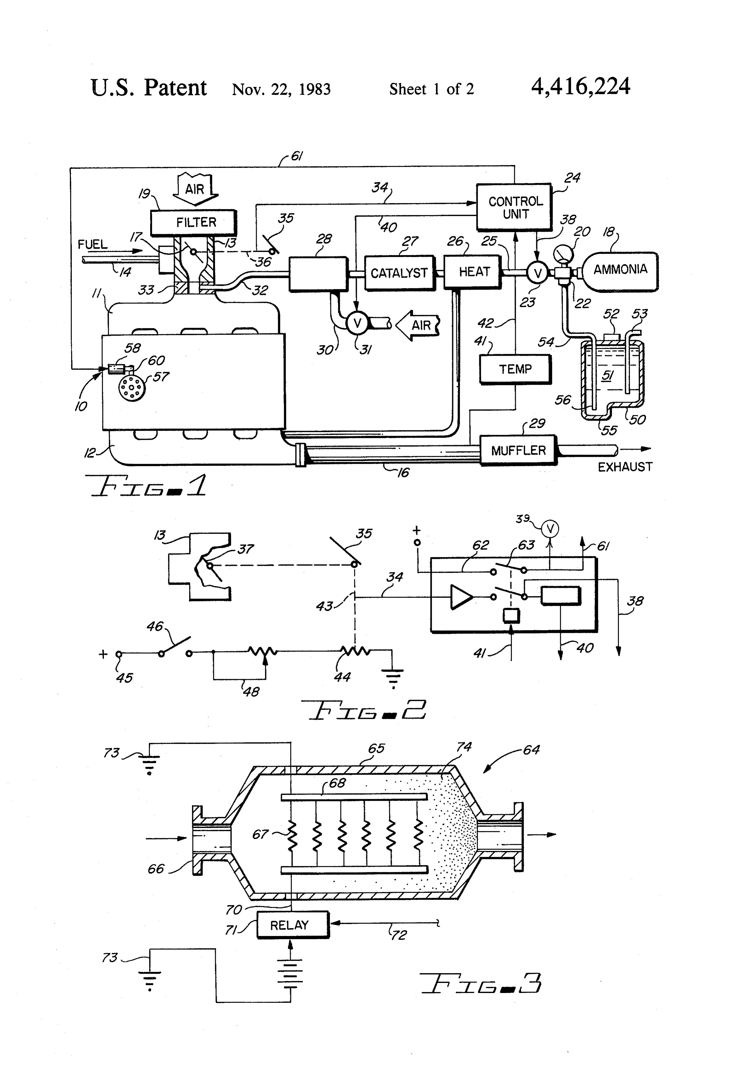
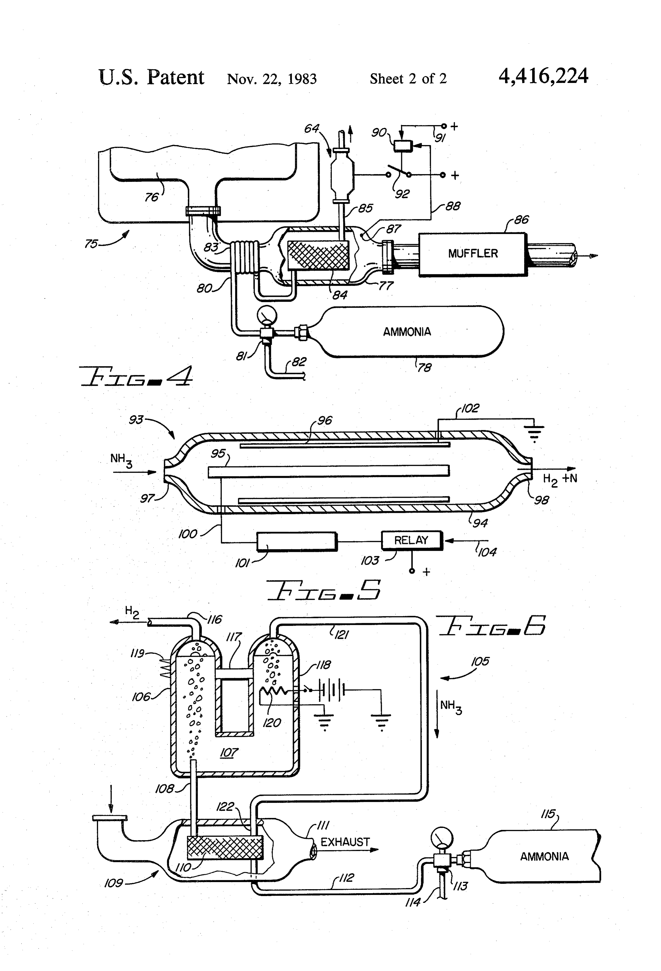
BRIEF DESCRIPTION OF THE DRAWINGS nium, or other known catalysts utilized in dissociating Other objects, features and advantages of the present ammonia. The catalyst can be coated onto or formed invention will be apparent from the written description with a ceramic honeycomb material or other material and the drawings, in which: 5 similarly used in three way catalytic converters and FIG. 1 is a diagrammatic view of an internal combus which is not readily damaged by high temperature. The tion engine fuel system in accordance with the present dissociated ammonia is fed into a mixing box 28 where invention; it is mixed with air from the line 30, which air is con FIG. 2 is a circuit diagram for the electronic control trolled by a varying solenoid valve 31 controlled by the for the internal combustion engine of FIG. 1; 10 control unit 24, as shown in FIG. 2, to vary the amount FIG. 3 is a sectional view of an auxiliary fuel dissocia of air in accordance with the amount of ammonia being tor; fed depending upon the engine operating conditions. FIG. 4 is a diagrammatic view of an auxiliary fuel The mixed air and dissociated ammonia is fed system utilizing a second auxiliary fuel dissociator; through the line 32 through an adapter plate 33 FIG. 5 is a sectional view of a second embodiment of 15 mounted between the carburetor and the intake mani an auxiliary dissociator utilizing a silent electrical dis fold. It will, of course, be clear that the auxiliary fuel charge; and and air can be fed at any position desired into the carbu FIG. 6 is a cutaway section and diagrammatic view retor or intake manifold, but needs to be controlled to of an ammonia separator for use in the present inven be varied in accordance with engine conditions, just as tion. 20 the flow of hydrocarbon fuel and air is controlled.
DESCRIPTION OF THE PREFERRED
A control unit 24 operates a valve 23 through an
EMBODIMENTS electrical conductor 38 and a valve 31 through an elec trical conductor 41. The control unit receives a temper
Referring to FIG. 1 of the drawings, an internal com ature reading from the temperature sensor 41 through bustion engine 10 is illustrated with a carburetor 13 25 the conductor 42 to determine when sufficient heat is feeding into an intake manifold 11 feeding into the en reached to dissociate the ammonia and thereby start gine block, which also has an exhaust manifold 12 con feeding the ammonia and added air to the engine. A nected thereto. The engine 10 is a standard internal control unit also has a conductor 61 which controls an combustion engine using refined hydrocarbon fuels fed electrical solenoid 58 connected to the distributor 57 from a fuel tank (not shown) through a fuel line 14 to 30 through an arm 60 so that the entire distributor can be the carburetor 13 while air from the atmosphere is fed shifted to advance the spark of the engine 10 at the same through an air filter 19 into the carburetor 13. A throttle time the engine is being leaned down by the addition of 17 located in the carburetor 13 is connected by throttle air through the line 30 and of auxiliary dissociated fuel linkage 36 to the accelerator pedal 35 for controlling the fed thereinto. The air and auxiliary fuel are controlled speed of the engine 10 by varying the fuel-air flow 35 by the accelerator linkage 36 which is connected through the carburetor. A fixed venturi carburetor is through a line 34 to the control unit 24, illustrated, but it should be clear that the invention will The pressure relief valve 22 has a line 54 coupled to work equally well with a fuel injection engine or a the output thereof and to a container 50, which may be variable venturi carburetor without departing from the the windshield wiper container for a vehicle, and which spirit and scope of the invention. The exhaust manifold 40 is filled with water 51 (or water having other chemicals 12 has an exhaust pipe 16 connected thereto through a therein), which readily absorbs the ammonia. One vol muffler 29. The exhaust pipe might also have a three ume of water will absorb approximately seven hundred way catalyst catalytic converter therein. An ammonia volumes of ammonia gas while making the water 51 a tank 18 for the storage of liquid anhydrous ammonia is better windshield cleaning agent. Additives for wind connected to a valve 20 and has a pressure relief valve 45 shield washer containers typically already have ammo 22 connected thereto for relieving pressure should the nia therein. The container 50 may have a deeper bottom pressure in the ammonia tank 18 exceed the set pressure for receiving the end 56 of the pipe 54 so that the end 56 of the valve 22. Such might happen if the ammonia tank will always be covered with water 51, even though the 18 got heated up above a predetermined temperature windshield washer tube 53 has emptied the container 50 while being substantially filled with liquid ammonia. 50 as far as it can. The container will also have a cap 52 for Ammonia tank 18 is connected through a valve 23 adding water thereto. This simple modification advan which is a variable solenoid control valve controlled by tageously prevents the relief valve from releading any a control cirucit of FIG. 2 for varying the feed of am ammonia into the atmosphere while increasing the monia to the engine 10. Ammonia is fed through the safety of the storage of the ammonia 18 and improving ammonia line 25 where it may be either a liquid or 55 the ability of the windshield washer of a vehicle to clean gaseous state, as desired. However, it is then fed into an the windshield.
ammonia catalytic dissociator separated to show heat 26 In the case of stationary engines, however, a separate and a catalyst 27, even though it should be clear that water container might be used, or in an open area the one combined unit is utilized. The heat is shown being ammmonia can be vented to the atmosphere, since am fed from the exhaust manifold 12, but it should also be 60 monia is commonly manufactured in the atmosphere clear that this is a diagrammatic illustration since the and is a common way of fixing nitrogen for use by catalytic dissociator would normally be mounted right plants.
to the end of the exhaust manifold 12. Once a predeter The control unit in FIG. 2 is a simplified electrical mined temperature range is reached in the ammmonia control embodiment of the invention, but it should be dissociator, the ammonia being fed from the tank 18 is 65 clear that a next generation control unit might typically fed as a gas through the dissociator where it is dissoci include an integratec circuit, such as a programed mi ated into hydrogen and nitrogen and may have a small croprocessor for receiving control signals not only from amount of ammonia still therein. The catalyst used may the throttle and temperature sensors, but other engine
Page 7
conditions as well, and for automatically controlling the oxygen sensor reads too lean. The vacuum modulator advance of the timing and opterating conditions of the system can be disabled by grounding the electrical con engine. In this embodiment, the accelerator pedal 35 is nections to the vacuum modulator, but it is more desir connected through a linkage 43 to the movable contact able to use a solenoid valve to close off the air intake to of a potentiometer 44 which is connected from an elec the vacuum modulator so that the vacuum is always trical terminal 45 through the ignition switch 46 supplied to the mixture controlled piston, thereby al through the potentiometer 44 through a line 34 to the ways reading at its maximum lean position to assist in control unit 24 to thereby vary the voltage in the line 34 leaning the engine when the engine is switched over to to control the unit 24. A variable resistance 48 can be an auxiliary fuel. The use of this system in a retrofit used to determine the minimum value of the signal of 10 vehicle, however, requires the approval of the appro the moving contact of the potentiometer 44. The con priate Governmental agencies, since it modifies an exist trol unit 24 may include an amplifier for amplifying the ing air pollution control device. However, the present signal from the line 34, as well as a relay or solenoid system is such that the normal three way catalyst can be switch actuated by thermal sensor (or thermostat) 41. eliminated since it has been shown that NO emissions The thermal switch disables the control unit 24 until a 15 form a curve in relation to the fuel-air ratio which sufficient temperature is reached in the exhaust mani reaches its maximum very near the stoichometric mix fold for dissociating the ammonia and allows the engine ture and drops off rapidly as the engine is leaned down. to run in a normal manner on a hydrocarbon fuel-air An electronic lean burning system such as used by the mixture. This prevents ammonia and air from being fed Chrysler Corporation at one time can reduce the NO. into the unit until sufficient heat is available to dissoci ate a portion of the ammonia and from leaning the en emissions as well as CO and hydrocarbon emissions by gine down prematurely to a condition in which the leaning the engine down to an approximately 18:1 fuel engine wouldn't run. A momentary delay circuit can air ratio, which approaches the upper limit lean burn for momentarily delay the signal in the line 40 to the valve most engines. The emissions curves show that leaning 31 to assure that the air and ammonia will reach the 25 an engine down to a fuel-air ratio of 22:1 substantially coupling plate 33 at the same time, so as not to momen eliminates both NOx and carbon monoxide emissions, tarily lean the engine 10 down prior to ammonia being while the hydrocarbons tend to increase. However, fed to the engine. The thermal switch 41 operates a hydrocarbons lean burning are much easier handled, and since the of the present invention is accomplished double pole, double throw switch with the switch con by the use of added hydrogen and nitrogen, it is be trolling the valve 31 also having a connection line 38 30 lieved that the hydrocarbons would also be reduced. connecting to the valve 23. A second switch 63 is con nected from an electrical terminal through a line 62 Turning now to FIGS. 3 through 5, an internal com through the switch 63 to an output line 61 which in turn bustion engine in accordance with the present invention is connected to the solenoid 58 for simultaneously ad is shown with a second auxiliary ammonia dissociator vancing the spark of the engine 10 as the dissociated 35 64 illustrated for dissociating ammonia with a cold en ammonia and air is fed to the engine with the normal gine so as to maintain the engine in a leaned down and hydrocarbon air-fuel mixture. This switch also actuates advanced spark system without having to switch back a solenoid valve or relay 39 in those engines using a and forth as illustrated in connection with FIGS. 1 and closed loop engine control. In a controlled loop engine 2. In FIG. 3, an auxiliary ammonia dissociator 64 has a control, an oxygen sensor is mount-d in the exhaust 40 casing 65 being partially filled with the catalyst 74. The manifold of the engine for determining the air-fuel mix casing 65 has an inlet opening 66 having a flange and an ture of the engine. This is used because a three way outlet opening at the other end thereof. Electrical bus catalyst is most effective within a narrow range of air bars 68 are mounted inside the casing 65 and have elec fuel ratios which is slightly on the rich side of stoichio trical elements 67, which may be of a nichrome (nickel metric air-fuel ratios (15:1). To reduce emissions re 45 and chromium alloy) type resistance heating elements, quires that the engine be run within this narrow fuel-air which advantageously makes a good catalyst for the ratio and an oxygen sensor utilizing zirconium coated catalytic dissociation of ammonia. One bus bar 68 is with platinum advantageously indicates the amount of connected to a ground 73 while the other is connected oxygen in the exhaust and whether the engine is running to an electrical line 70 through the casing 65 to a relay lean or rich or to either side of the narrow range that the 50 71. The relay is actuated by a line 72 which may be three way catalyst is optimized. This signal is normally connected to a thermal sensor or thermostat for disen fed to the microprocessor but may be fed to a simple gaging the relay once the exhaust manifold is heated analog or digital control for controlling a vacuum mod sufficiently to operate the normal catalytic dissociator. ulator or an electric motor or a solenoid. The vacuum A battery is shown connected to the relay being modulator or electric motor responds responsive to a 55 grounded by line 73. This embodiment would be placed signal generated responsive to the oxygen sensor signals in an engine as illustrated in FIG. 4 following a normal to drive a mixture control piston in the carburetor (or catalytic dissociator 77 and would be switched out as the vacuum in a fuel bowl), which simultaneously leans soon as sufficient heat in the catalytic dissociator 77 and enrichens the carburetor high speed jet, as well as allowed the catalyst chamber 84 to dissociate the am the idle mixture feed. This is typically done with a con 60 monia.
stant vacuum modulator varying the vacuum by a sole The embodiment of FIG. 3 would normally require a noid valve responding to the signals generated from the short heating period, such as required by glow plugs in oxygen sensor signals to allow atmospheric air to be fed diesel engines, to heat up sufficiently to dissociate the to the vacuum. In a system using an electric motor, the ammonia for starting the engine. A thermal sensor 87 is motor is driven forward of backward, depending upon 65 connected through a line to a solenoid actuated switch which terminal receives the current to move tapered or relay 90 which actuates the switch 92. Switch 92 is metering rods so that a relay can switch the terminal normally open and is closed when there is insufficient connections to maintain a lean fuel-air mixture when the temperature from the sensor 87 to thereby actuate the
Page 8
heating elements 67 of FIG. 3. An electrical line 91 is gen and nitrogen to be collected at the top and fed to connected to the relay to actuate the relay 90. the engine while any residue ammonia will be trapped in FIG. 4 has the exhaust manifold 76 of the engine 75 the water 107. One volume of water will hold approxi connected to the catalytic dissociator 77 to pass exhaust mately seven hundred volumes of ammonia gas at nor gases and heat around the catalyst chamber 84 and out mal temperatures. Two chambers 106 and 118 are con the exhaust pipe and muffler'86. The ammonia stored in nected by pipe 117 and also along the base. Chamber ammonia tank 78 is fed through a pressure relief valve 118 has an electrical heating element 120 operated by 81 which has a coupling line 82 which can be coupled to the battery and connected through a switch and is con a windshield washer container as illustrated in FIG. 1. nected fairly near the surface of the liquid in the con Line 80 couples the ammonia tank 78 around a coiled O tainer 118. Heating the water to boiling will remove all preheater wrapped around an exhaust pipe portion of of the ammonia gas from the water. The gas is collected the catalytic dissociator 77 prior to the ammonia gas on the top of the container 118 and fed through the pipe going into the catalyst chamber 84 and from the catalyst 121 back through the opening 122 into the catalyst bed chamber 84 through the line 85 and into the second 110. The heater 120 can be cycled on and off as needed. auxiliary catalytic dissociator 64 into the carburetor or 15 Inasmuch as the heater is heating the liquid, cooling fins intake manifold of the engine. 119 are provided on chamber 106 to keep this liquid as FIG. 5 shows an alternate embodiment for temporar cool as possible to hold a larger percentage of ammonia ily dissociating ammonia until the engine heat allows relative to the chamber 118 top portion which is being the primary catalytic dissociator to become operational. heated to remove the ammonia.
The auxiliary dissociator 93 has a casing 94 which can 20 The ammonia separator 105 advantageously can be be a ceramic material as desired and has a central elec utilized with those engines having parts therein which trode 95 along with a spaced electrode 96 which may be are corroded by ammonia. However, it should be clear a thin metal plate wrapped around the cylindrical hous that small amounts of ammonia in a hydrocarbon atmo ing 94. The electrode 96 can also be placed outside of sphere will burn and there has been an indication that it the housing 94 or formed within the housing rather than 25 might even reduce emissions from an internal combus located inside, as shown in the drawing. The housing 94 tion engine. However, since the btu fuel value of a has an inlet 97 for ammonia to be fed to the dissociator pound of ammonia is about half that of a pound of gaso and an exit 98 for the egress of hydrogen and nitrogen. line, the ammonia is better utilized being dissociated to The electrode 96 is connected through a line 102 to utilize the hydrogen for leaning the internal combustion ground, while the electrode 95 is connected through a 30 engine to improve the engine's efficiency and to reduce line 100 to a tesla coil and vibrator 101 for increasing emissions.
the voltage applied to the electrode 95. A relay. 103 is It should be clear at this time that an improvement to connected to box 101 to apply a voltage when the relay an internal combustion engine using dissociated ammo is actuated from the line 104. Line 104 operates the same nia as an auxiliary fuel has been illustrated which can be as in FIG. 4 to disengage the dissociator when sufficient 35 utilized in a normal hydrocarbon fuel-air operation heat is reached by the temperature sensor 87, so that the mode or can be switched to a leaned down engine of primary ammonia dissociator is operational. In lieu of a higher efficiency utilizing hydrogen dissociated from temperature sensor, a hydrogen sensor can be placed in ammonia and varied in accordance with the operating the line 85 of FIG. 4 to indicate when hydrogen is being conditions of the engine to drive the engine. It should fed from the catalytic dissociator 84 to thereby switch 40 also be clear that a system has been provided for start off the auxiliary dissociator 64. The dissociator in FIG. ing the engine on a leaned basis utilizing hydrogen gen 4 works on the basis that a silent electrical discharge erated by the waste heat catalytic dissociator and a through an ammonia gas will dissociate the ammonia means to improve the efficiency of the dissociation of gas, and while this takes a certain amount of electrical the ammonia. Accordingly, the present invention is not power, it has the advantage of being a substantially 45 to be limited to those forms shown, which are to be instantaneous dissociation and is only operational for a considered illustrative rather than restrictive. short period of time, so that the engine can be started I claim:
immediately and remain leaned down in operation at all 1. An improvement in an internal combustion engine times without the cut-ins and outs of air and ammonia, having an auxiliary fuel system comprising in combina as well as advancing the spark upon appropriate condi SO tion:
tions being reached. an internal combustion engine having fuel feed means Turning now to FIG. 6, an ammonia separator is for feeding a hydrocarbon fuel-air mixture to said illustrated connected to the ammonia dissociator. The engine combustion chambers; catalystic dissociator 109 is connected to the exhaust an auxiliary fuel system feeding an auxiliary fuel to manifold and has a catalyst chamber 110 therein. The 55 said internal combustion engine with said hydro ammonia separator has a dual chamber 106 and 118 carbon fuel-air mixture;
filled with water 107 or other material for absorbing a first auxiliary fuel dissociation means for dissociat ammonia. Ammonia gas is fed from the compressed ing the fuel in said auxiliary fuel system being fed to ammonia tank 115 through pressure relief valve 113 said internal combustion engine using exhaust heat which has a line 114 coupled as desired to a container, 60 from said engine;
such as a windshield washer container, as shown in a second auxiliary fuel dissociation means for dissoci FIG. 1. The line 112 couples the ammonia tank 115 to ating the fuel in said auxiliary fuel system being fed the ammonia dissociator 109, catalyst chamber 110 and to said internal combustion engine when said en from there through line 108 into the ammonia separator gine has insufficient heat from said exhaust heat to 106. Dissociated gas would normally contain primarily 65 dissociate said auxiliary fuel, whereby said internal hydrogen and nitrogen, but generally contains a residue combustion engine runs on dissociated auxiliary of ammonia in a typical dissociation by heated catalyst. fuel in combination with a hydrocarbon fuel-air Bubbling gas through the water 107 allows the hydro mixture.
Page 9
2. An improvement in an interal combustion engine in second auxiliary fuel dissociation means upon said first accordance with claim 1, in which said second auxiliary auxiliary fuel dissociation means dissociating ammonia. fuel dissociation means includes control means for dis 11. An improvement in an internal combustion engine abling said second auxiliary fuel dissociation means in accordance with claim 10, in which said second auxil responsive to said first auxiliary fuel dissociation means iary fuel dissociation means includes a vibrator in com becoming operational. bination with said coil to produce an increased voltage 3. An improvement in an internal combustion engine in said auxiliary fuel dissociation means. in accordance with claim 2, in which said control means 12. An improvement in an internal combustion engine includes a heat sensor for disabling said second auxiliary in accordance with claim 1, in which said second auxil fuel dissociation means upon a predetermined tempera iary fuel feed system is mounted in the auxiliary fuel line
ture level being reached in said first auxiliary fuel disso being fed from said first auxiliary fuel dissociation ciation means.
4. An improvement in an internal combustion engine means to said engine combustion chamber. in accordance with claim 3, in which said second auxil 13. An improvement in an internal combustion engine having an auxiliary fuel system comprising in combina iary fuel dissociation means includes a container having 15 tion: N a catalyst and heating means therein for heating ammo an internal combustion engine having fuel feed means nia gas passing therethrough in the presence of a cata for feeding a fuel-air mixture to said engine com lyst, thereby dissociating said ammonia. bustion chambers;
5. An improvement in an internal combustion engine in accordance with claim 4, in which said second auxil 20 an auxiliary fuel system for feeding auxiliary fuel to iary fuel dissociation means includes a series of electri said internal combustion engine; cal heaters mounted in said housing, said heating ele a fuel dissociation means for at least partially dissoci ments being made of a catalyst for dissociating ammo ating auxiliary fuel and said auxiliary fuel system nia. being fed into said internal combustion engine; and 6. An improvement in an internal combustion engine 25 a gas separation means for receiving said auxiliary fuel from said fuel dissociation means and remov in accordance with claim 5, in which said second auxil iary fuel dissociation means includes a relay actuated by ing gas from said fuel following dissociation, said a temperature sensor for cutting said heating elements in gas separation means including a connected dual and out responsive to the heat in said engine exhaust chamber housing at least partially filled with water system. 30 and having said fuel dissociation means coupled to 7. An improvement in an internal combustion engine one chamber for feeding dissociated gas through in accordance with claim 1, in which second auxiliary the water therein and the other chamber having fuel dissociation means includes a housing having an heating means mounted for removing gas there inlet and an outlet and at least one electrode mounted from.
therein and a second electrode mounted to generate a 35 14. An improvement in an internal combustion engine silent electrical discharge through ammonia gas being in accordance with claim 13, in which the fuel dissocia passed therethrough for dissociating said ammonia gas. tion means is a catalytic ammonia dissociator and said 8. An improvement in an internal combustion engine gas separation means removes residual ammonia left in in accordance with claim 7, in which said first electrode said dissociated gas.
is mounted in the center portion of said housing and said 40 15. An improvement in an internal combustion engine electrode is mounted along the surface of said housing. in accordance with claim 13, in which said gas separa 9. An improvement in an internal combustion engine tion means includes a feedback line connected from said in accordance with claim 8, in which one said electrode gas separation means to said auxiliary fuel dissociation is connected to a coil for increasing the voltage thereto means for returning ammonia released from said liquid to create said silent electrical discharge in said second 45 in said gas separation means container. auxiliary fuel dissociation means. 16. An improvement in an internal combustion engine 10. An improvement in an internal combustion engine in accordance with claim 15, in which said first chamber in accordance with claim 9, in which said coil is actu has cooling fins thereon.
ated by a relay actuated by a sensor to disable said sk k s: : t
Provenance
- Collection
- Cited prior art
- Original PDF
- patentimages.storage.googleapis.com →
- Filed
- 1982-01-18
- Pages
- 9
- Method
- pdftotext (the PDF's own text layer) + pdftoppm 300dpi page scans
- Source
- Google Patents bibliographic record
- Granted
- 1983-11-22
- Inventors
- William M. Hobby; Joseph M. Valdespino
- Transcribed from
- patentimages.storage.googleapis.com →