patent · US4223642
Method for improving the combustion efficiency of hydrocarbon fuel in the internal combustion engine
23 September 1980
Page 1 — bibliographic record
United States Patent (19) 11) 4,223,642 Okubo (45) Sep. 23, 1980 (54) METHOD FOR IMPROVING THE 2,888,913 6/1959 Emmett et al. .................. 123/119 E COMBUSTION EFFICIENCY OF 3,150,645 9/1964 Mrstik et al. ........................ 123/1 A HYDROCARBON FUEL IN THE INTERNAL 3,174,472 3/1965 Balogh.......... ... 123/119 E COMBUSTION ENGINE 3,800,761 4/1974 Sata ..................................... 123/. A 3,826,815 7/1974 Mavrovic. ... 423A356 76) Inventor: Yoshinori Okubo, 5-21, 3,900,554 8/1975 Lyon ............. ... 123/1 A Kentoku-machi 1-chome, Oita-shi, 3,985, 107 10/1976 Ueno et al. .... ... 123/1 A Oita-ken, Japan 4,067,299 1/1978 Lindenmaier ....................... 123A1. A (21) Appl. No.: 856,431 - Primary Examiner-Charles J. Myhre Assistant Examiner-Craig R. Feinberg 22 Filed: Dec. 1, 1977 Attorney, Agent, or Firm-Jordan and Hamburg (30) Foreign Application Priority Data 57 ABSTRACT Dec. 15, 1976 JP Japan ................................ 51/151420 A method which improves the combustion efficiency of 51) Int. Cl. ........................ F02B 43/08; FO2B 43/10 fuel in the internal combustion engine is disclosed. The 52) U.S.C. .................................... 123/1 A; 123/436; method is substantially characterized in that a small 123/3; 123/575 R; 422/148; 422/164 amount of ammonia gas is incorporated into the hydro 58 Field of Search .................. 123/1 A, 3, DIG. 12, carbon fuel in any position between an air intake port 123/119 E; 422/148, 164, 305; 423/356, 420 and an intake manifold of the engine. Due to the above (56) References Cited addition of ammonia, the combustion of the hydro-car bon fuel in the combustion chamber is enhanced with
1,490,975 4/1924. Howard ... ... 123/DIG. 12 2,140,254 12/1938 Zavka .............................. 123/119 E 15 Claims, 9 Drawing Figures
saaSaaSas
Page 2
Drawing sheet — no readable text.
Page 3
Drawing sheet — no readable text.
Page 4
Drawing sheet — no readable text.
Page 5
Drawing sheet — no readable text.
Page 6
Drawing sheet — no readable text.
Page 7
form prior to the mixture of fuel and air. When the fuel
METHOD FOR IMPROVING THE COMBUSTION is in a liquid form, the additive is dissolved in the fuel EFFICIENCY OF HYDROCARBON FUEL IN THE beforehand (Japanese patent laid open publication NTERNAL COMBUSTION ENGINE SH049-44006).
The methods discussed above have employed the
BACKGROUND OF THE INVENTION compound composed of hydrocarbon and oxygen for This invention relates to a method for improving the obtaining complete combustion of hydrocarbon fuel. combustion efficiency of gasoline fuel in the internal Meanwhile, a method which uses a compound con combustion engine mounted on an automobile, particu 10 taining nitrogen as a fuel additive is known. When the larly to such a method which is characterized by adding operators of racing cars want extra performance for ammonia gas, which can be produced from any desired limited periods of time, they add 5 percent nitro ammonia compounds such as liquid ammonia or ammo methane to the methanol in the fuel tank. It has also nium carbonate, to the gaseous or mist form of gasoline been reported that combustion is increased by mixing to be incorporated into the engine, whereby the com gasoline, benzene and methanol. In conjunction with bustion efficiency of the engine is enhanced while the 5 the above method, U.S. Pat. No. 3,807,972 (granted on amounts of pollutants contained in the discharged gas Apr. 30, 1974) discloses a method for improving the are minimized. combustion efficiency wherein the mixture consisting of Conventionally, for decreasing the amount of pollut 75 percent methanol, 5 percent nitro-methane, 2 percent ants contained in the gas discharged from the internal nitro-benzene and 18 percent acetone is mixed with combustion engine, several methods have been devel 20 water and the thus produced mixture is vaporized. Sub oped and used on a trial basis including a group of meth sequently the vaporized mixture is injected into the ods which have treated the discharged gas after com intake manifold of the internal combustion engine, bustion and a group of methods which have added some whereby the combustion performance of the engine is additives to the hydrocarbon fuel prior to the combus enhanced while the composition of the discharged gas is
improved.
In the latter group of methods, although they have The inventor of this invention also has continued a worked effectively in some particular conditions or study on the method for enhancing the combustion cases, most of them have incurred a decrease in combus efficiency of the fuel in the internal combustion engine tion efficiency.
As a fuel additive composition which can decrease gas, has 30 and unexpectedly found that when the ammonia produced from a compound which can produce the amount of pollutants in the discharged gas while keeping a high combustion efficiency, a composition such ammonia gas, is mixed with the intake air and which comprises a major amount of white oil, 1 to 4 subsequently is slightly mixed with the gaseous or mist percent by volume, based on the total volume of com form of gasoline to be charged into the internal combus position and about 0.02 to 0.1 percent by volume, based 35 tion engine, the output of the engine is greatly enhanced on the total volume of the composition of oil of orange resulting in a reduced consumption of fuel. is disclosed in U.S. Pat. No. 3,820,962 (patented on June The applicant also has found that addition of such 28, 1974). mixture into the fuel can improve the combustion effi Meanwhile, for obtaining the complete combustion of cient without substantially increasing the adverse nitro fuel in the internal combustion engine, methods which 40 genAccordingly, oxide content within the discharged gas.
it is an object of the present invention inject a reforming agent into the gasoline vapor have been developed wherein a method which injects the to provide a method for improving the combustion water vapor into the intake manifold of the internal efficiency of hydrocarbon fuel within the combustion combustion engine or a method which injects the alco chamber of the internal combustion engine which is hols, the mixture of water and alcohol, or the mixture of 45 characterized by the addition of ammonia gas or a vola water, alcohol, propylene and acetone have been well tile ammonium compound to the gaseous or mist form known. It is believed that the addition of water vapor or of gasoline in the fuel stream of the internal combustion alcohol enhances combustion and produces a dis engine.
charged gas of favorable composition. It is another object of the present invention to pro Although alcohol which contains oxygen facilitates SO vide such a method for improving the combustion effi the complete combustion as has been described above, ciency while decreasing the amount of pollutants within lower alcohol such as methanol requires a delicate tech the discharged gas.
nique in mounting the supply device thereof and causes It is a further object of the present invention to pro the methanol residue by thermal decomposition which vide a device applicable to the method of this invention is troublesome in disposal. Furthermore, the alcohol 55 which can continuously add the ammonia gas produced does not have compatibility with hydrocarbon. from ammonium compound to the hydrocarbon fuel in Meanwhile, the oxygen-containing alcohol has a ten the internal combustion engine.
dency to produce nitrogen oxide at high temperatures It is a still further object of the present invention to of more than 1200° C. while it causes incomplete com provide such a device which is of a simple and yet rigid bustion at low temperatures. Accordingly, in the above 60 construction so that it can be easily installed in an auto method a compound is employed besides alcohol for mobile of any desired type.
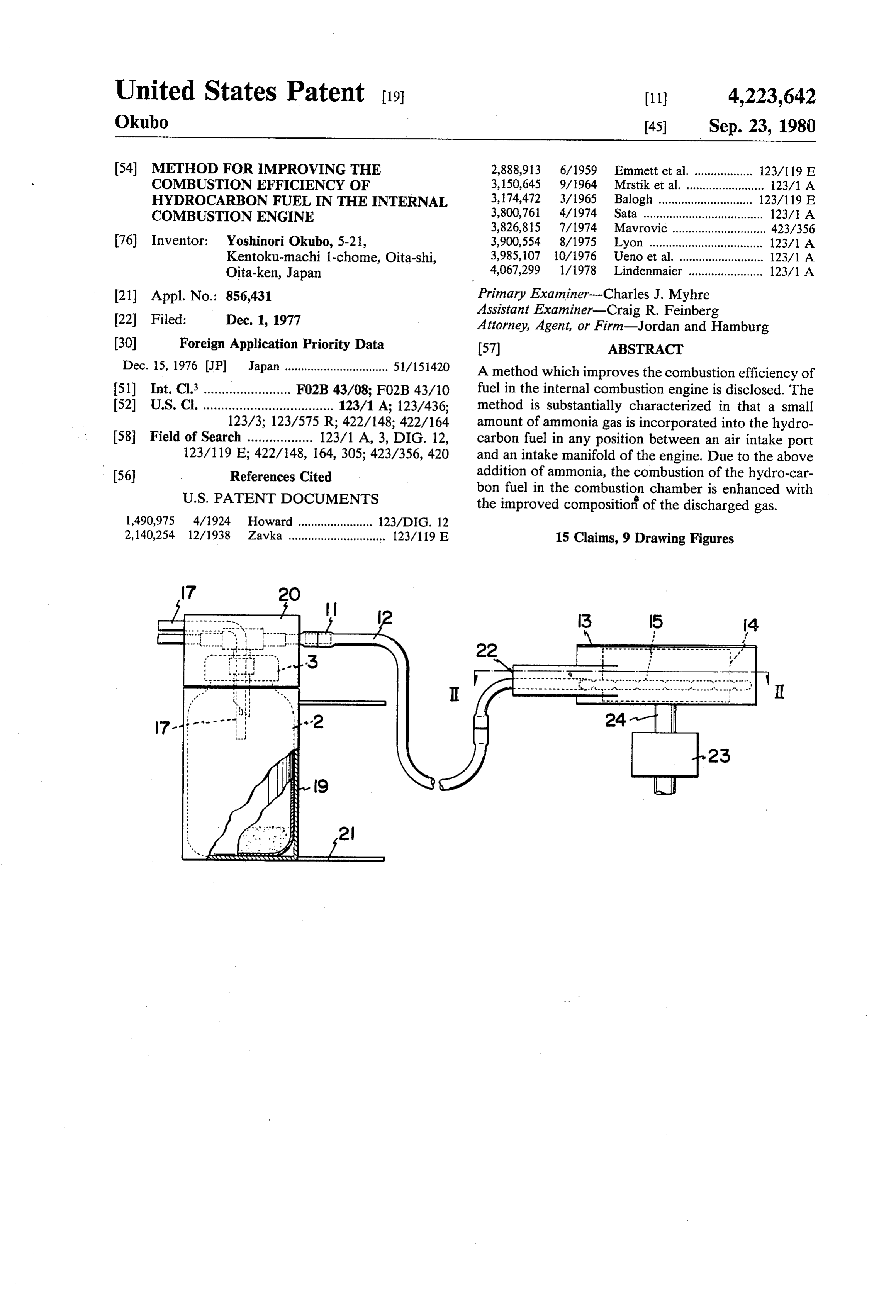
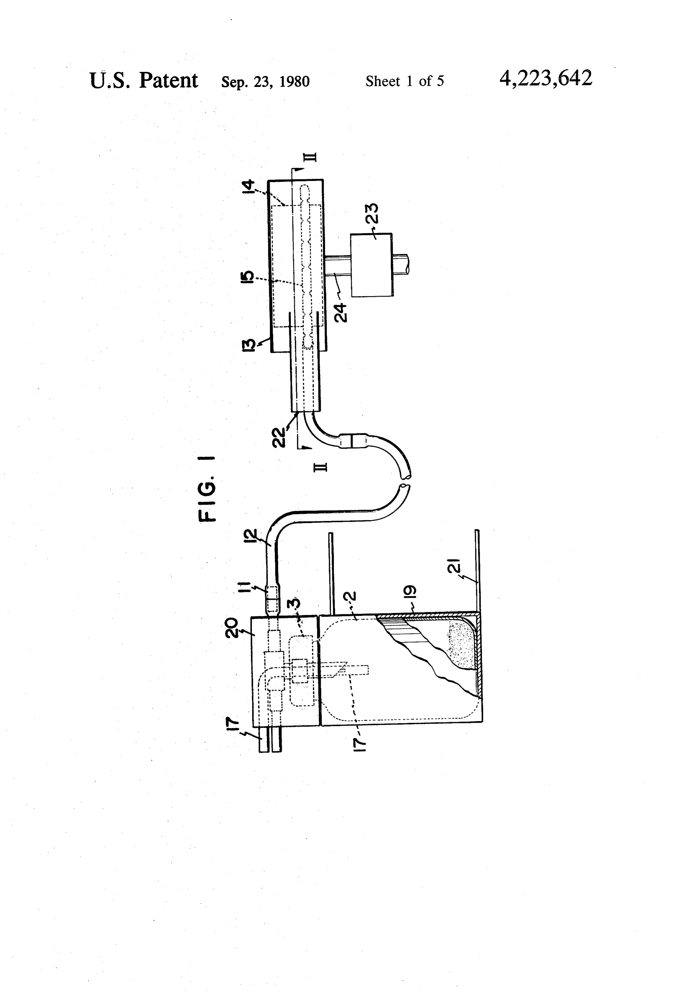
providing complete combustion without producing These and other objects of the invention will be seen nitrogen oxide. Also, started from the same technical by reference to the following description, taken in con idea is a method which adds acetate, a mixture of ace nection with the accompanying drawings. tate and alcohol, or a mixture of the above components 65 BRIEF EXPLANATION OF THE DRAWINGS with water into the fuel before combustion. In the above method, when the fuel is in a gaseous form, the FIG. 1 is an entire front view of the device employed above additive is incorporated into the fuel in a mist for the method of this invention.
Page 8
FIG. 2 is an enlarged partial left side view of the ammonium bicarbonate is sublimated into the gaseous device with a part broken away showing the upper form.
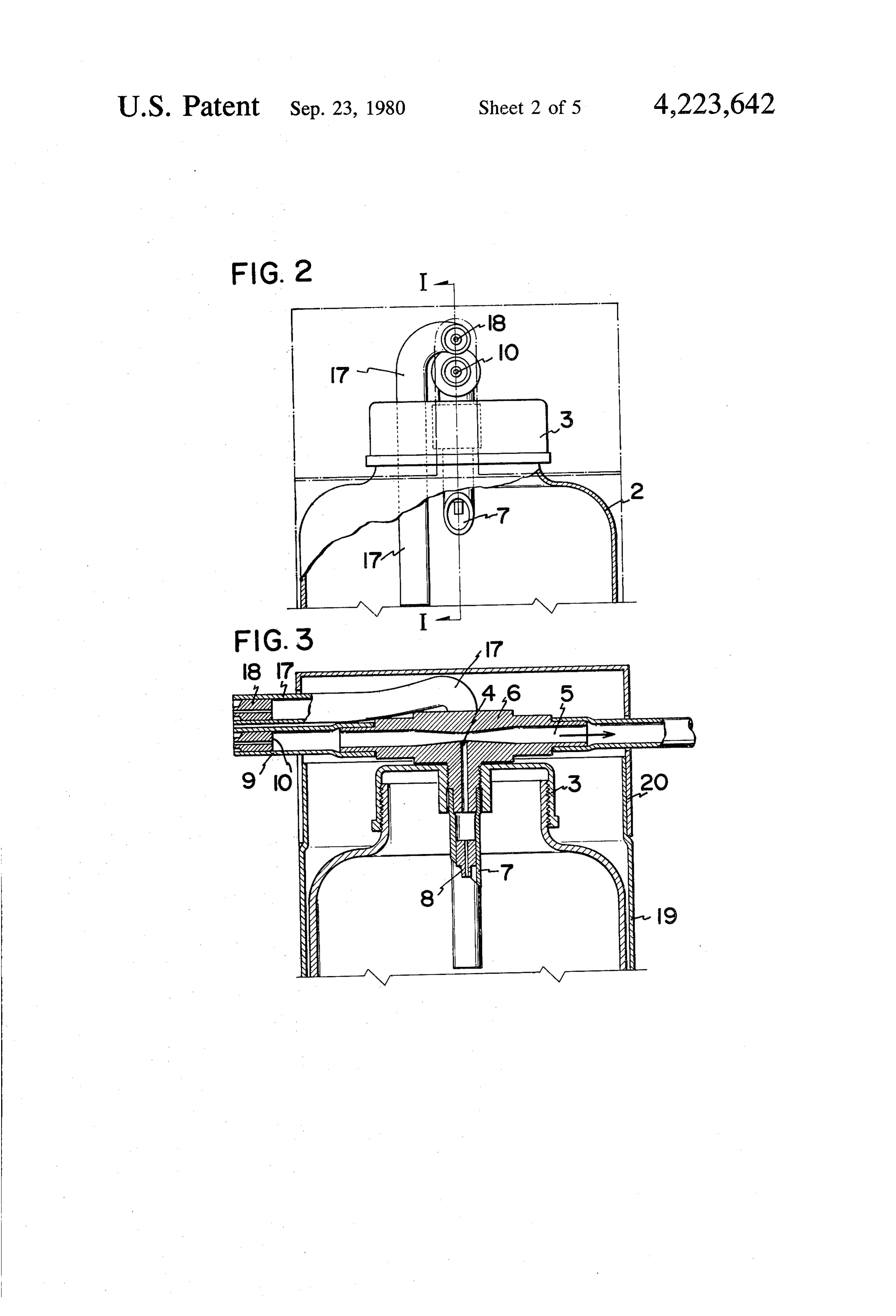
portion of the container. Ammonium carbamate is decomposed in the same FIG. 3 is a longitudinal cross-sectional front view of manner as that of ammonium carbonate and ammonium the device taken along the line I-I of FIG. 2. 5 bicarbonate.
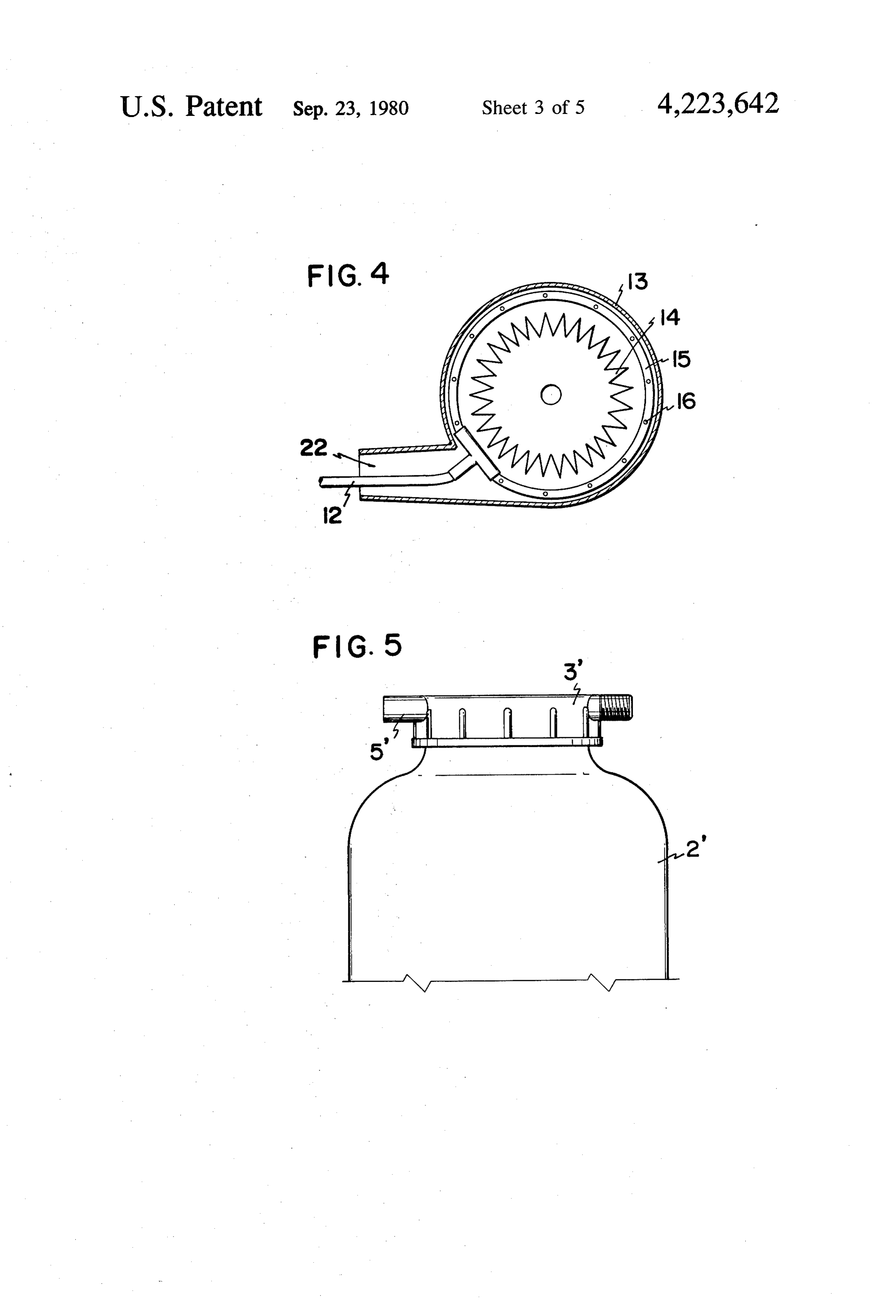
FIG. 4 is a transverse cross-sectional plan view of the In the method of this invention, an additive such as device taken along the line II-II of FIG. 1. ammonia or a volatile ammonia compound is employed FIG. 5 is a front view of a modification of the device in the following manner.
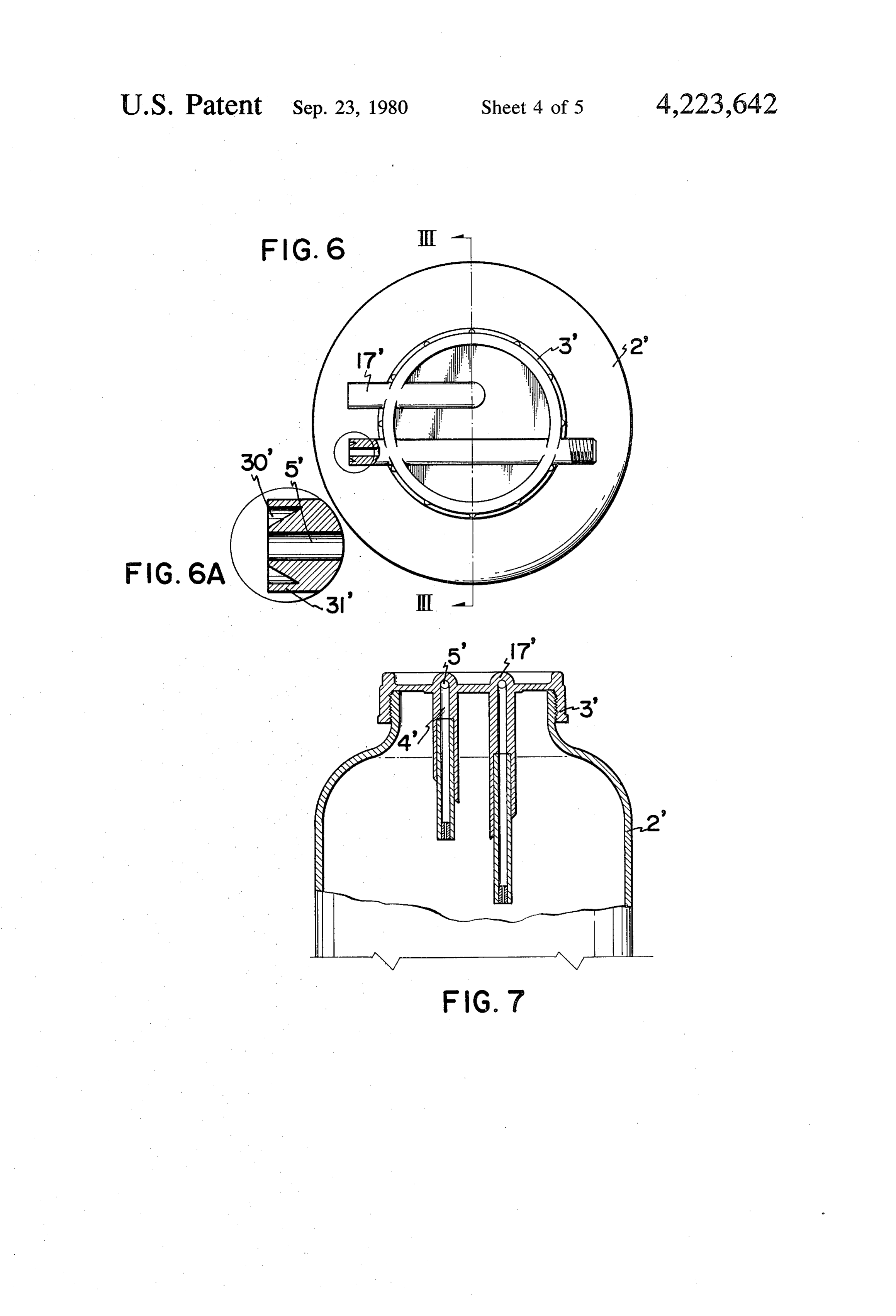
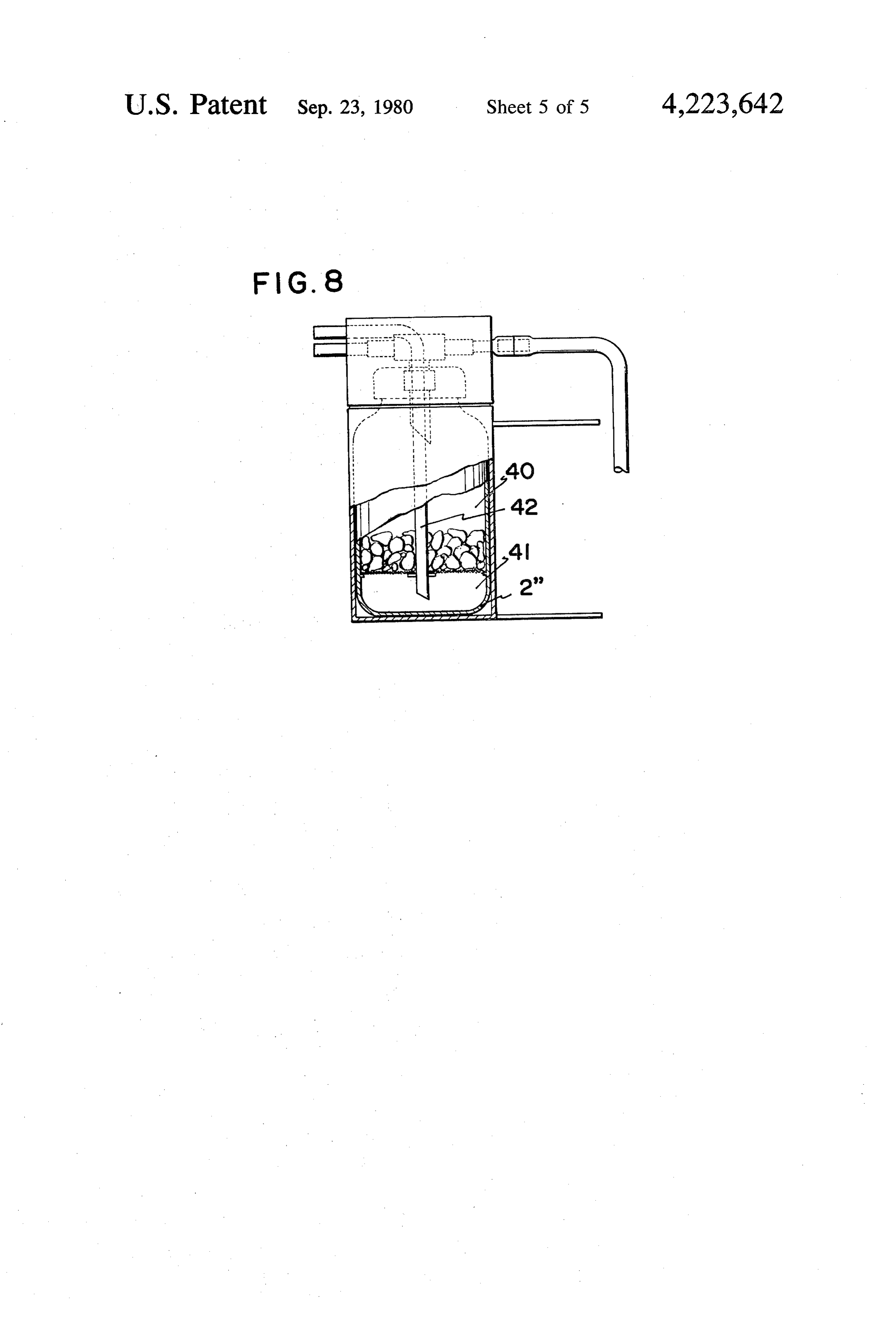
of this invention. In the case of a solid ammonia compound, since the FIG. 6 is a plan view of the above device. O compound gradually decomposes and produces anmo FIG. 6A is an enlarged view of the portion of FIG. 6 nia gas, it is preferable to use this compound in the enclosed within the circle shown in FIG. 6. method of this invention. Furthermore, a solid ammonia FIG. 7 is a longitudinal cross-sectional view of the compound requires no specific safety measures which device taken along the line III-III of FIG. 6. are necessary in liquid ammonium. FIG. 8 is a front view with a part broken away of However, since the decomposition rate of a solid another modification of the device of this invention. ammonia compound varies to some extent depending on the temperature, the container in which the gas is pro
DETALED DESCRIPTION OF THE duced should preferably be held at a constant tempera DISCLOSURE ture so as to supply a constant amount of ammonia gas The internal combustion engine to which the present 20 into a fuel such as gasoline.
invention is applicable includes all types of internal A device which is applicable to the method of this combustion engines which use hydrocarbon as a fuel, invention is hereinafter described wherein the device particularly the engines of automobiles, trucks, tractors supplies the ammonia gas produced from solid ammo nium carbonate into the intake air within the air cleaner.
and airplanes. Solid ammonium carbonate is contained within a As fuels whose combustion efficiency will be im 25 container which comprises a lid portion 3 and a cylin proved by the application of the method of this inven drical container body 2. A vertical flow-out passage 4 tion, any internal combustion engine fuels which are through which ammonia ignited by an electric spark can be considered. Such monium carbonate flows gas sublimated from solid am fuels include commercially available petroleum distil 30 tion 3. The upper end of theispassage out provided at the lid por lates such as automobile gasoline having the fraction of middle portion of a horizontal passage 45 isformingjoined to a
distillate of 20 to 30 centigrade or airplane gasoline shaped communicating chamber within a three-way having the fraction of distillate of 35° to 165 centi joint member 6. For increasing the amount of ammonia grade.
Furthermore, if conditions will be satisfied, the 35 gas from the container, a venturi construction may be provided on the three-way joint member 6.
method of this invention may be applicable to a diesel A flow regulating valve 8 is attached to the bottom engine which uses diesel oil. end of a vertical vinyl tube 7 of a desired length which, It is needless to say that the method of this invention can employ conventional additives of various purposes in turn, has the upper end thereof connected with the vertical portion of the joint member 6. This flow regu such as an anti-erosion agent, anti-static agent, anti-oxi 40 lating valve 8 has its lower opening within the container dation agent, anti-freezing agent or anti-knocking agent 2.
together with the additive of this invention. The horizontal both-open-ended passage 5 of the As compounds which can produce the gaseous com three-way joint member 6 has one end thereof commu pound applicable to the method of this invention, am nicated with an oncoming air flow by way of a heat monium carbonate, ammonium bicarbonate and ammo 45 resistant silicon pipe 9. This silicon pipe 9 is provided nium carbamate can be mentioned. Liquid ammonia with a flow regulating valve 10 for regulating the air may be contained in cylinders. The ammonia water may flow into the horizontal flow passage 5. preferably contain 20 to 30 percent by weight of ammo The horizontal passage 5 has another end communi
cated by way of a heat-resistant tube 12 with a circular
The ammonium carbonate and ammonium bicarbon 50 vinyl tube 15 which substantially encloses an air filter 14 ate are obtained commercially in solid form wherein the within an air cleaner 13. The above heat-resistant tube ammonium carbonate exists in the form of a mixture or 12 is provided with a flow regulating valve 11 in the double salt of ammonium hydrogencarbonate midst thereof.
(NH4HCO3) and ammonium carbamate A plurality of openings 16 are equidistantly formed (H2NCO2NH4). The ammonium carbonate is decom 55 on the periphery of the circular vinyl tube 15 such that posed in the air into ammonia, carbon dioxide and water the ammonia gas passing through the heat resistant tube and eventually is decomposed into bicarbonate and 12 can enter into the air cleaner 13.
ammonia. This decomposition proceeds in the air even Referring back to the container, an air introduction at room temperature while generating a quantity of pipe 17 which introduces the air (pressure) into the heat. When the temperature reaches 58 C. the decom- 60 container is also provided at the lid portion. This air position rapidly progresses. Furthermore, the ammo introduction pipe 17 is both-open-ended having one end nium carbonate is sublimated by the above heat quantity open to an on coming air flow and another end open to into the gaseous form. the inside of the container body 2. A flow regulating Ammonium bicarbonate (NH4HCO3) is also decom valve 18 is provided at the outside extremity of the pipe posed in the air into ammonia and carbon dioxide. The 65 17. A casing 19 which solidly encases the container 2 is decomposition progresses together with the elevation provided with a rotating lid 20 on the upper portion of temperature and when the temperature exceeds more thereof such that the lid 20 is rotatable relative to the than 60 C. the decomposition rapidly proceeds and casing 19. A mounting plate 21 facilitates the mounting
Page 9
of the casing 19 to any desired position adjacent to the 31' extending from the bottom periphery of the frust internal combustion engine of an automobile. conical portion 30.
An air inlet 22 supplies sufficient air into the air The air flow passages 4 and 5' formed in the lid por cleaner 13 while a communicating tube 24 connects the tion 3' respectively may preferably have a diameter air cleaner 13 with a carburetor 23. ranging from 1.0 mm to 1.6 mm which corresponds to The casing 19 which encases the ammonium carbon the diameter of the flow regulating valves 10 and 18 of ate container is fixedly placed at a desired airy position the original construction.
in the front portion of the automobile by means of the The second modification of the device is character mounting plate 21. Such a placement is inevitably neces ized in that an air (pressure) is introduced into an air sary so that the entire device used for the method of this 10 chamber formed below a solid ammonium compound in invention can be protected from high radiation heat a container as shown in FIG. 8.
generated by the engine. In FIG. 8, a container 2" is divided into an upper It is also necessary that the openings of the tubes ammonium which open to the atmosphere are directed in alignment 15 chamber 41 compound chamber 40 and a lower air by a net screen of a desired mesh. In the with the moving direction of the automobile. upper chamber 40, a bulky solid ammonium compound At the same time, the other end of the tube is con nected to the circular vinyl pipe 15 disposed within the is contained. An air introduction pipe 42 which has one air cleaner 13. end open to an oncoming air flow has another end open After the above mounting operation, the engine of in the lower air chamber 41. Due to the above construc the automobile is started. 0 tion, the production of ammonia gas might be en Throughout the running of the automobile, the regu chanced.
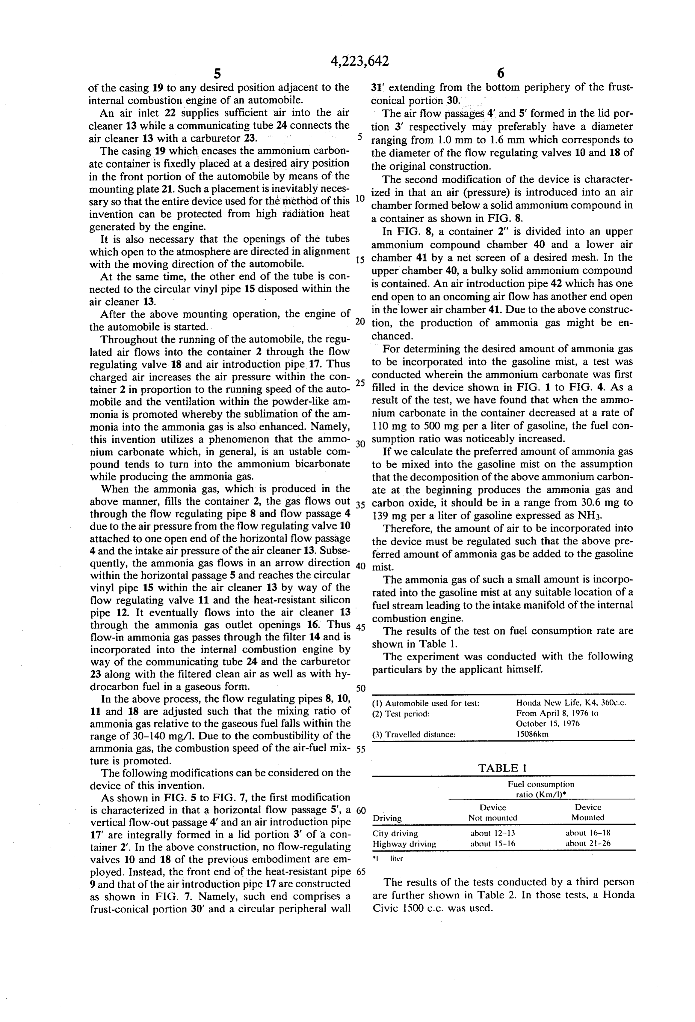
lated air flows into the container 2 through the flow For determining the desired amount of ammonia gas regulating valve 18 and air introduction pipe 17. Thus to be incorporated into the gasoline mist, a test was charged air increases the air pressure within the con 25 conducted wherein the ammonium carbonate was first tainer 2 in proportion to the running speed of the auto filled in the device shown in FIG. 1 to FIG. 4. As a mobile and the ventilation within the powder-like am result of the test, we have found that when the ammo monia is promoted whereby the sublimation of the am nium carbonate in the container decreased at a rate of monia into the ammonia gas is also enhanced. Namely, 110 mg to 500 mg per a liter of gasoline, the fuel con this invention utilizes a phenomenon that the ammo 30 sumption ratio was noticeably increased. nium carbonate which, in general, is an ustable com If we calculate the preferred amount of ammonia gas pound tends to turn into the ammonium bicarbonate to be mixed into the gasoline mist on the assumption while producing the ammonia gas. that the decomposition of the above ammonium carbon When the ammonia gas, which is produced in the ate at the beginning produces the ammonia gas and above manner, fills the container 2, the gas flows out 35 carbon oxide, it should be in a range from 30.6 mg to through the flow regulating pipe 8 and flow passage 4 139 mg per a liter of gasoline expressed as NH3. due to the air pressure from the flow regulating valve 10 Therefore, the amount of air to be incorporated into attached to one open end of the horizontal flow passage the device must be regulated such that the above pre 4 and the intake air pressure of the air cleaner 13. Subse ferred amount of ammonia gas be added to the gasoline quently, the ammonia gas flows in an arrow direction mist.
within the horizontal passage 5 and reaches the circular The ammonia gas of such a small amount is incorpo vinyl pipe 15 within the air cleaner 13 by way of the rated into the gasoline mist at any suitable location of a flow regulating valve 11 and the heat-resistant silicon fuel stream pipe 12. It eventually flows into the air cleaner 13 combustionleading engine.
to the intake manifold of the internal through the ammonia gas outlet openings 16. Thus 45 The results of the test on fuel consumption rate are flow-in ammonia gas passes through the filter 14 and is shown in Table 1.
incorporated into the internal combustion engine by The experiment was conducted with the following way of the communicating tube 24 and the carburetor particulars by the applicant himself. 23 along with the filtered clean air as well as with hy
In the above process, the flow regulating pipes 8, 10, (1) Automobile used for test: Honda New Life, K4, 360c.c. 11 and 18 are adjusted such that the mixing ratio of (2) Test period: From April 8, 1976 to ammonia gas relative to the gaseous fuel falls within the October 15, 1976 range of 30-140 mg/l. Due to the combustibility of the (3) Travelled distance: 508km ammonia gas, the combustion speed of the air-fuel mix 55 ture is promoted. TABLE 1. The following modifications can be considered on the device of this invention. Fuel consumption As shown in FIG. 5 to FIG. 7, the first modification ratio (Kmal)
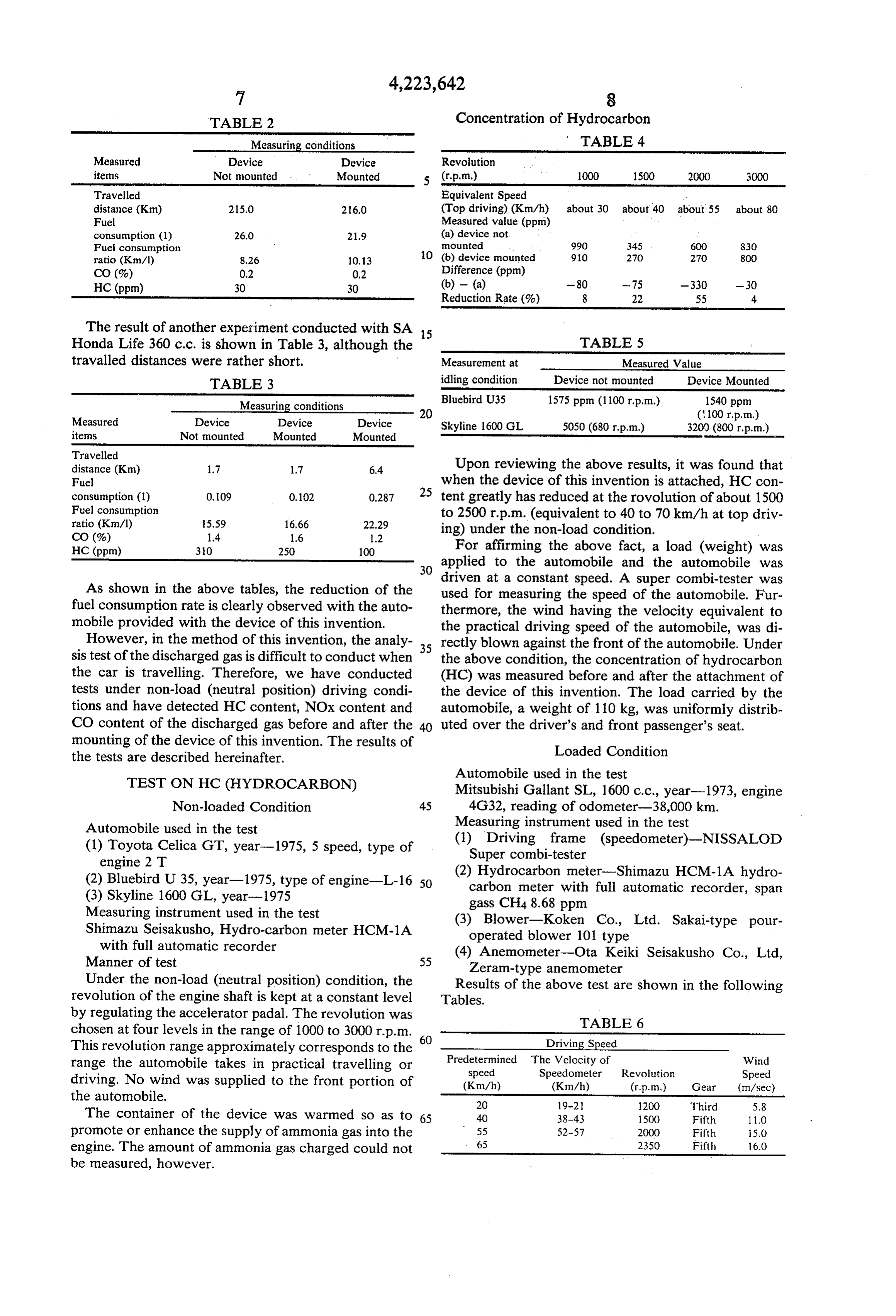
is characterized in that a horizontal flow passage 5', a 60 Driving Not mounted Mounted vertical flow-out passage 4 and an air introduction pipe 17" are integrally formed in a lid portion 3 of a con City driving about 12-13 about 16-18 tainer 2'. In the above construction, no flow-regulating Highway driving about 15-16 about 21-26 valves 10 and 18 of the previous embodiment are em * liter ployed. Instead, the front end of the heat-resistant pipe 65 9 and that of the air introduction pipe 17 are constructed The results of the tests conducted by a third person as shown in FIG. 7. Namely, such end comprises a are further shown in Table 2. In those tests, a Honda frust-conical portion 30' and a circular peripheral wall Civic 1500 c.c. was used.
Page 10
TABLE 2 Concentration of Hydrocarbon
Measuring conditions TABLE 4
Measured Device Device Revolution items Not mounted Mounted 5 (r.p.m.) 1000 1500 2000 3000 Travelled Equivalent Speed distance (Kim) 215.0 216.0 (Top driving) (Km/h) about 30 about 40 about 55 about 80 Fuel Measured value (ppm) consumption (1) 26.0 21.9 (a) device not
Fuel consumption O mounted 990 345 600 830 ratio (Km/1) 8.26 10.13 (b) device mounted 910 270 270 800 CO (%) 0.2 0.2 Difference (ppm)
HC (ppm) 30 30 (b) - (a) - 80 -75 -330 -30 Reduction Rate (%) 8 22 55 4
The result of another experiment conducted with SA 15
Honda Life 360 c.c. is shown in Table 3, although the TABLE 5 travalled distances were rather short. Measurement at Measured Value TABLE 3 idling condition Device not mounted Device Mounted
Bluebird U35 1575 ppm (1100 rp.m.) 1540 ppm
Measured Device Device Device
Skyline 1600 GL 5050 (680 r.p.m.) 3200 (800 r.p.m.)
items Not mounted Mounted Mounted
Travelled distance (Kim) 1.7 1.7 6.4 Upon reviewing the above results, it was found that Fuel 25 when the device of this invention is attached, HC con consumption (1)
Fuel consumption 0.109 0,102 tent greatly has reduced at the rovolution of about 1500
to 2500 rp.m. (equivalent to 40 to 70 km/h at top driv
CO (%) 1.4 1.6 i.2 ing) under the non-load condition.
HC (ppm) 30 250 100 For affirming the above fact, a load (weight) was 30 applied to the automobile and the automobile was driven at a constant speed. A super combi-tester was
As shown in the above tables, the reduction of the used for measuring the speed of the automobile. Fur fuel consumption rate is clearly observed with the auto thermore, the wind having the velocity equivalent to mobile provided with the device of this invention. the practical driving speed of the automobile, was di However, in the method of this invention, the analy 35 rectly blown against the front of the automobile. Under sistest of the discharged gas is difficult to conduct when the above condition, the concentration of hydrocarbon the car is travelling. Therefore, we have conducted (HC) was measured before and after the attachment of tests under non-load (neutral position) driving condi the device of this invention. The load carried by the tions and have detected HC content, NOx content and automobile, a weight of 110 kg, was uniformly distrib CO content of the discharged gas before and after the 40 uted over the driver's and front passenger's seat. mounting of the device of this invention. The results of Loaded Condition the tests are described hereinafter.
Automobile used in the test
TEST ON HC (HYDROCARBON) Mitsubishi Gallant SL, 1600 c.c., year-1973, engine Non-loaded Condition 45 4G32, reading of odometer-38,000 km. Automobile used in the test Measuring instrument used in the test (1) Toyota Celica GT, year-1975, 5 speed, type of (1) Driving frame (speedometer)-NISSALOD engine 2 T Super combi-tester (2) Bluebird U 35, year-1975, type of engine-L-16 50 (2) Hydrocarbon meter-Shimazu HCM-1A hydro (3) Skyline 1600 GL, year-1975 carbon meter with full automatic recorder, span Measuring instrument used in the test gass CH48.68 ppm
Shimazu Seisakusho, Hydro-carbon meter HCM-1A (3) Blower-Koken Co., Ltd. Sakai-type pour with full automatic recorder operated blower 101 type
Manner of test 55 (4) Anemometer-Ota Keiki Seisakusho Co., Ltd, Zeram-type anemometer
Under the non-load (neutral position) condition, the Results of the above test are shown in the following revolution of the engine shaft is kept at a constant level Tables.
by regulating the accelerator padal. The revolution was TABLE 6 chosen at four levels in the range of 1000 to 3000 r.p.m.
This revolution range approximately corresponds to the Driving Speed range the automobile takes in practical travelling or Predetermined The Velocity of Wind speed Speedometer Revolution Speed driving. No wind was supplied to the front portion of (Km/h) (Km/h) (r.p.m.) Gear (m/sec) the automobile.
The container of the device was warmed so as to 65 40 38-43 1500 Fifth 10 promote or enhance the supply of ammonia gas into the 55 52-57 2000 Fifth 15.0 engine. The amount of ammonia gas charged could not 65 2350 Fifth 6.0 be measured, however.
Page 11
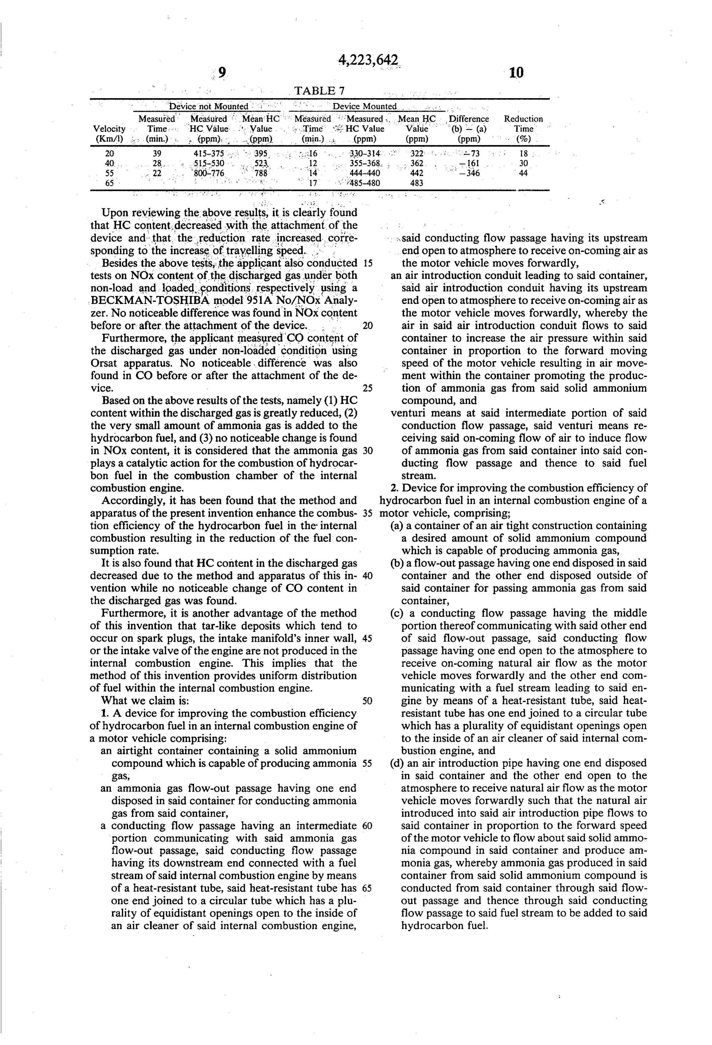
TABLE 7
Device not Mounted . . . . . Device Mounted , ,, ,
Measured Measured Mean HC. Measured 'Measured. Mean HC Difference Reduction
Velocity Time, , HC Value. . . . . Value. ... is Time: ; HC Value Value (b) - (a) Time (Km/) ... (min) - , (ppm). . . .(ppm). (min.) (ppm) (ppm) (ppm) : . . (%) 20 39 415-375. - 395, , , , ; 16 . . . . . 330-314. ... 322. . . . . . .73 . . . . 18
65 ; : " " '' is 17 '.' 485-480 483
Upon reviewing the above results, it is clearly found that HC content decreased with the attachment of the said conducting flow passage having its upstream device and that the reduction rate increased corre sponding to the increase of travelling speed. . . end open to atmosphere to receive on-coming air as Besides the above tests, the applicant also conducted 15 the motor vehicle moves forwardly, tests on NOx content of the discharged gas under both an air introduction conduit leading to said container, non-load and loaded conditions respectively using a said air introduction conduit having its upstream BECKMAN-TOSHIBA model 951A No/NOx Analy end open to atmosphere to receive on-coming air as zer. No noticeable difference was found in NOx content 20 the motor vehicle moves forwardly, whereby the before or after, the attachment of the device. air in said air introduction conduit flows to said Furthermore, the applicant measured CO content of container to increase the air pressure within said the discharged gas under non-loaded condition using container in proportion to the forward moving Orsat apparatus. No noticeable difference was also speed of the motor vehicle resulting in air move found in CO before or after the attachment of the de ment within the container promoting the produc W1Ce. 25 tion of ammonia gas from said solid ammonium Based on the above results of the tests, namely (1) HC compound, and content within the discharged gas is greatly reduced, (2) venturi means at said intermediate portion of said the very small amount of ammonia gas is added to the conduction flow passage, said venturi means re hydrocarbon fuel, and (3) no noticeable change is found ceiving said on-coming flow of air to induce flow in NOx content, it is considered that the ammonia gas 30 of ammonia gas from said container into said con plays a catalytic action for the combustion of hydrocar ducting flow passage and thence to said fuel bon fuel in the combustion chamber of the internal Stream.
combustion engine. 2. Device for improving the combustion efficiency of Accordingly, it has been found that the method and hydrocarbon fuel in an internal combustion engine of a apparatus of the present invention enhance the combus 35 motor vehicle, comprising;
tion efficiency of the hydrocarbon fuel in the internal (a) a container of an air tight construction containing combustion resulting in the reduction of the fuel con a desired amount of solid ammonium compound sumption rate. which is capable of producing ammonia gas, It is also found that HC content in the discharged gas (b) a flow-out passage having one end disposed in said decreased due to the method and apparatus of this in container and the other end disposed outside of vention while no noticeable change of CO content in said container for passing ammonia gas from said the discharged gas was found. container,
Furthermore, it is another advantage of the method (c) a conducting flow passage having the middle of this invention that tar-like deposits which tend to portion thereof communicating with said other end occur on spark plugs, the intake manifold's inner wall, 45 of said flow-out passage, said conducting flow or the intake valve of the engine are not produced in the passage having one end open to the atmosphere to internal combustion engine. This implies that the receive on-coming natural air flow as the motor method of this invention provides uniform distribution vehicle moves forwardly and the other end com of fuel within the internal combustion engine. municating with a fuel stream leading to said en What we claim is: 50 gine by means of a heat-resistant tube, said heat 1. A device for improving the combustion efficiency resistant tube has one end joined to a circular tube of hydrocarbon fuel in an internal combustion engine of which has a plurality of equidistant openings open a motor vehicle comprising: to the inside of an air cleaner of said internal com an airtight container containing a solid ammonium bustion engine, and compound which is capable of producing ammonia 55 (d) an air introduction pipe having one end disposed gas, in said container and the other end open to the an ammonia gas flow-out passage having one end atmosphere to receive natural air flow as the motor disposed in said container for conducting ammonia vehicle moves forwardly such that the natural air gas from said container, introduced into said air introduction pipe flows to a conducting flow passage having an intermediate 60 said container in proportion to the forward speed portion communicating with said ammonia gas of the motor vehicle to flow about said solid ammo flow-out passage, said conducting flow passage nia compound in said container and produce am having its downstream end connected with a fuel monia gas, whereby ammonia gas produced in said stream of said internal combustion engine by means container from said solid annonium compound is of a heat-resistant tube, said heat-resistant tube has 65 conducted from said container through said flow one end joined to a circular tube which has a plu out passage and thence through said conducting rality of equidistant openings open to the inside of flow passage to said fuel stream to be added to said an air cleaner of said internal combustion engine, hydrocarbon fuel.
Page 12
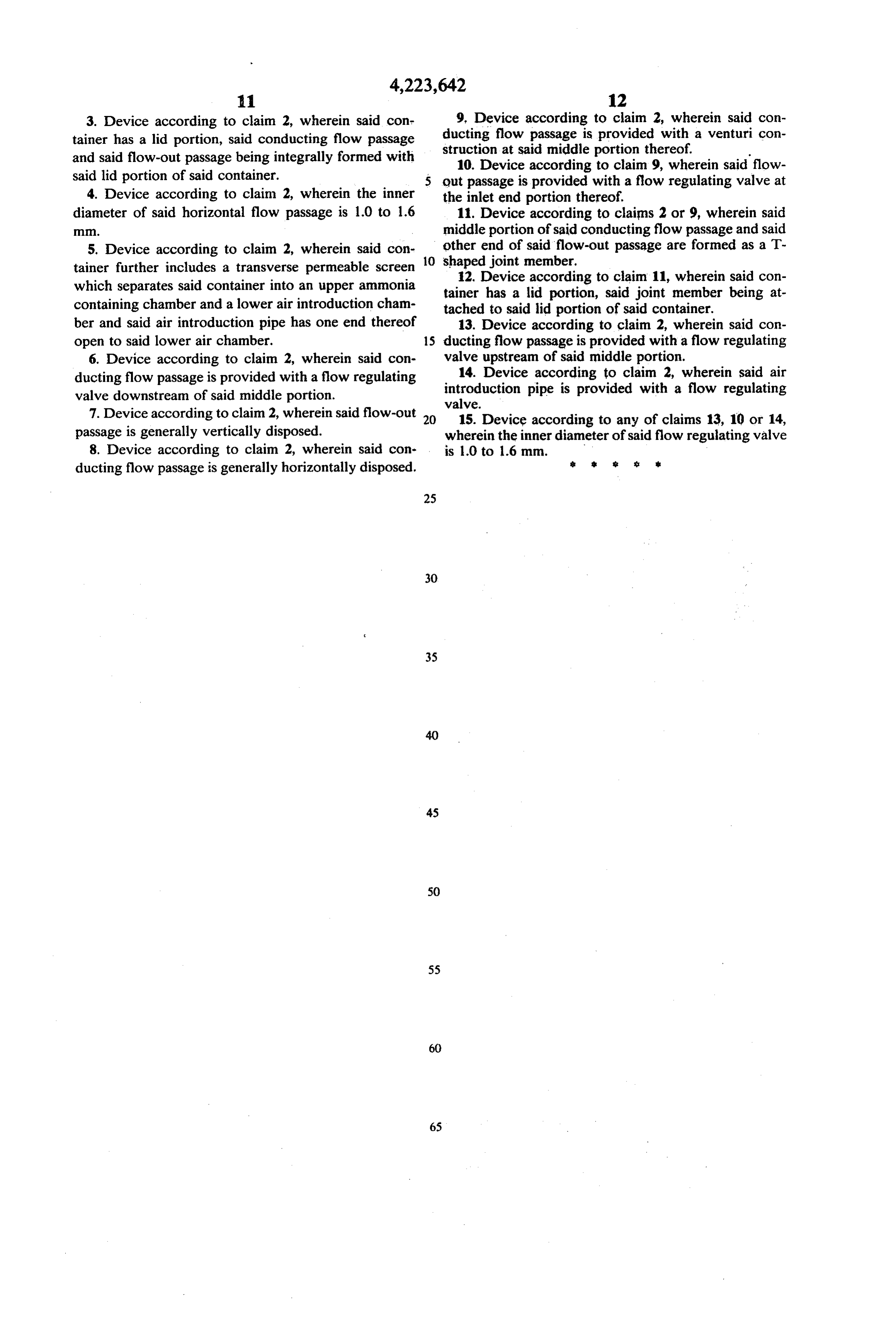
3. Device according to claim 2, wherein said cont 9, Device according to claim 2, wherein said con tainer has a lid portion, said conducting flow passage ducting flow passage is provided with a venturi con and said flow-out passage being integrally formed with struction at said middle portion thereof. said lid portion of said container. 10. Device according to claim 9, wherein said flow out passage is provided with a flow regulating valve at 4. Device according to claim 2, wherein the inner the inlet end portion thereof.
diameter of said horizontal flow passage is 1.0 to 1.6 11. Device according to claims 2 or 9, wherein said middle portion of said conducting flow passage and said 5. Device according to claim 2, wherein said con other end of said flow-out passage are formed as a T tainer further includes a transverse permeable screen O shaped 12.
joint member.
Device according to claim 11, wherein said con which separates said container into an upper ammonia tainer has a lid portion, said joint member being at containing chamber and a lower air introduction cham tached to said lid portion of said container. ber and said air introduction pipe has one end thereof 13. Device according to claim 2, wherein said con open to said lower air chamber. 15 ducting flow passage is provided with a flow regulating 6. Device according to claim 2, wherein said con valve upstream of said middle portion.
ducting flow passage is provided with a flow regulating 14. Device according to claim 2, wherein said air valve downstream of said middle portion. introduction pipe is provided with a flow regulating valve.
7. Device according to claim 2, wherein said flow-out 20 15. Device according to any of claims 13, 10 or 14, passage is generally vertically disposed. wherein the inner diameter of said flow regulating valve 8. Device according to claim 2, wherein said con is 1.0 to 1.6 mm.
ducting flow passage is generally horizontally disposed. s t s s
Provenance
- Collection
- Cited prior art
- Original PDF
- patentimages.storage.googleapis.com →
- Filed
- 1977-12-01
- Pages
- 12
- Method
- pdftotext (the PDF's own text layer) + pdftoppm 300dpi page scans
- Source
- Google Patents bibliographic record
- Granted
- 1980-09-23
- Inventors
- Yoshinori Okubo
- Transcribed from
- patentimages.storage.googleapis.com →