patent · US4385615
Fuel system for diesel engines
31 May 1983
Page 1 — bibliographic record
United States Patent (19) 11) 4,385,615 Keane 45) May 31, 1983 (54) FUEL SYSTEM FOR DESEL ENGINES FOREIGN PATENT DOCUMENTS 75) Inventor: Robert S. Keane, Orange, Calif. 3017325 11/1980 Fed. Rep. of Germany ...... 123/514 (73) Assignee: Fuel Dimensions, Inc., Anaheim, Primary Examiner-Ronald H. Lazarus Calif. Attorney, Agent, or Firm-Willie Krawitz
(21) Appl. No.: 82,419 Fuel for a diesel engine is fed to the engine through a 22) Filed: Oct. 5, 1979 small float tank provided with a fuel heater. A cooling unit is employed to cool overheated fuel recycled from 51) Int. Cl. ............................................. F02M 37/00 the engine. A temperature controlled valve is utilized to 52 U.S. C. .................................... 123/514; 123/516; divert recycled fuel from the cooling unit through the 123/557 float tank and back to the engine if the recycled fuel is 58 Field of Search ............... 123/514, 516, 525,527, sufficiently cool. The fuel heater, cooling unit and valve 123/557, 541, 25 E, 25 F are adapted to optimize fuel temperature based on en gine performance design.
(56) References Cited Water, propane, LPG, etc. also may be injected into the
2,599,699 6/1952. Dilworth ............................. 123/514 bustion process and fuel economies. 4, 175,527 l. lvl979 Sanada ................................ 123/514 4,343,283 8/1982 Shepherd ............................ 123/514 14 Claims, 5 Drawing Figures
to-K> O
ENGINE 3O 32
Page 2
Drawing sheet — no readable text.
Page 3
Drawing sheet — no readable text.
Page 4
However, this would require excessive power in the
FUEL SYSTEM FOR DIESEL ENGINES case of heating, and is impractical in the case of cooling. While earlier engines were low powered with a large
BACKGROUND OF THE INVENTION number of gear shiftings to accommodate for various This invention relates to a new and improved fuel speeds, loads, grades, etc., the newer diesel engines feed system for diesel engines, and more specifically, to have a greater horsepower at lower rpm and fewer gear a fuel feed system which supplies fuel to the engine at shiftings. This in turn enables faster trip times and hence controlled temperatures to improve engine perfor a more economical operation. However, these newer mance. Water, LPG and alcohol injection may be uti 10 engines are more sensitive to fuel temperature control in lized to reduce fuel consumption, lower NOx emissions order to achieve their maximum design performance, and reduce engine deposits. and the increased cost of fuel has reduced their eco Various problems are encountered when starting or nomic gains.
operating large diesel truck engines in cold weather, a The desire for water injection or supplemental fuel principle one being the use of cold fuel. Usually, the fuel 15 injection into the engine air intake manifold has known. must be pre-heated and this is both time consuming and desireable effects such as increased power, but adequate expensive.
These problems have become somewhat more aggra delivery able, and systems for fuel and water have proven unsuit a satisfactory temperature control system for vated in recent years due to the increased use of higher fuel has not been developed. boiling point wax fractions in the fuel. These wax frac 20 tions tend to crystallize out in engine parts and fuel lines THE INVENTION more readily in cold weather and make starting and According to the invention, a temperature controlled operating even more difficult.
In addition to starting problems, diesel engines are fuel feeding system for a diesel engine is provided com designed for optimum performance using fuel within a prising: a main fuel supply tank and pumping means certain temperature range. For example, typical Cum 25 therefor; a float tank fed from the main fuel tank for. mins engines operate best with fuel in the temperature providing fuel to the engine at a controlled temperature; range of about 94 F. to 104 F. and it is most important heating means associated with the float tank; means for that the fuel temperature be controlled to within this returning the cooled fuel to the float tank; and, means to range at all times. Hence, in the summer, the fuel should 30 adjust the float tank temperature thereby feeding fuel to be cooled down to about 94 F., while in the winter, the adjust the float tank temperature thereby feeding fuel to fuel should be heated in excess of about 94 F. Accord the engine within a suitable temperature range. ingly, if the engine fuel runs too cold or too hot, perfor During engine start-up, say in cold weather, fuel from mance will be impaired because the feed rates for fuel the main fuel supply is pumped to the float tank, heated, and air are optimized when operating within the above 35 and then fed to the cold engine; return fuel directed to temperature range. Thus, during cold starting, it is obvi the float tank will further heat incoming fuel. When the ously important to employ a warm or hot fuel depend engine has reached its operating temperature, heating of ing on ambient temperature. On the other hand, after the float tank, such as by an electrical element may be running temperatures are attained, it may be preferable to supply the fuel at cooler temperatures, particularly if discontinued. Conversely, if the ambient temperature is the engine is running in an excessively hot ambient 40 excessively hot, it may be advisable to cool the fuel temperature. prior to use by the engine. This is accomplished by Normally, part of the cooling in 'a' diesel engine is passing recycled hot fuel from the engine through a accomplished via fuel returned to the main fuel tank; 'cooling system such as a water or air cooler, and direct the returned fuel represents about three times the fuel ing the cooled fuel through the float tank and back into actually burned. However, when the ambient tempera 45 the engine. In conjunction with the usual air cooling ture exceeds about 100 F., the main fuel tank tempera fans, use of cooled fuel in a hot or overheated engine is ture may approach about 180' F. which is nearly at the obviously quite beneficial since it is applied directly to engine running temperature. - the engine components and also conforms to engine It has been found that a fuel density decrease due to design criteria for fuel temperatures. a temperature increase will cause a 1% decrease in 50 As an optional consideration, running fuel consump horsepower for each 10 F. rise in fuel temperature tion (i.e. flow rate) may be indicated by means of, say, a above about 94 F. Hence, if the engine temperature is digital LED display for viewing by the vehicle opera 180° F., and the fuel tank temperature is, say, 160 F., tor. Total fuel consumption may be displayed remotely the horsepower loss is approximately 7.5% depending from the operator to provide an independent check of on the fuel density curve. Conversely, if the ambient 55 fuel consumption for trip recording and fuel mileage temperature is too cold, the return fuel will not heat the computation.
fuel tank to 94 F.; this will cause the fuel density to The invention also enables use of a pneumatically increase and exceed the air supply to the engine intake. driven fuel totalizer counter activated by means of the Consequently, the fuel supply will be too rich, causing fuel supply pump during operation of the system; this poor combustion characteristics and carbon deposits to provides a mechanical form. Overall, fuel atomization of the fuel injection is tion. The counter maycounter
record of fuel consump locked and secured for sur optimized when the fuel at the inlet pump is about 94 veillance purposes to provide a record of fuel consumed F-104 F. and the engine temperature is a constant 180
F. for fuel tax computation. Thus, trucks equipped with One solution for effectively controlling fuel tempera 65 power take-off devices used for unloading, drilling, etc., ture to accommodate rapidly changing engine condi may utilize a record of fuel consumed during off-road tions caused by ambient temperature, engine load and operations and deduct the tax payable from road tax traffic conditions would be to heat or cool the fuel tank. assessments.
Page 5
BRIEF DESCRIPTION OF THE DRAWINGS tween the float 21 and the pump 11 provides float accu racy.
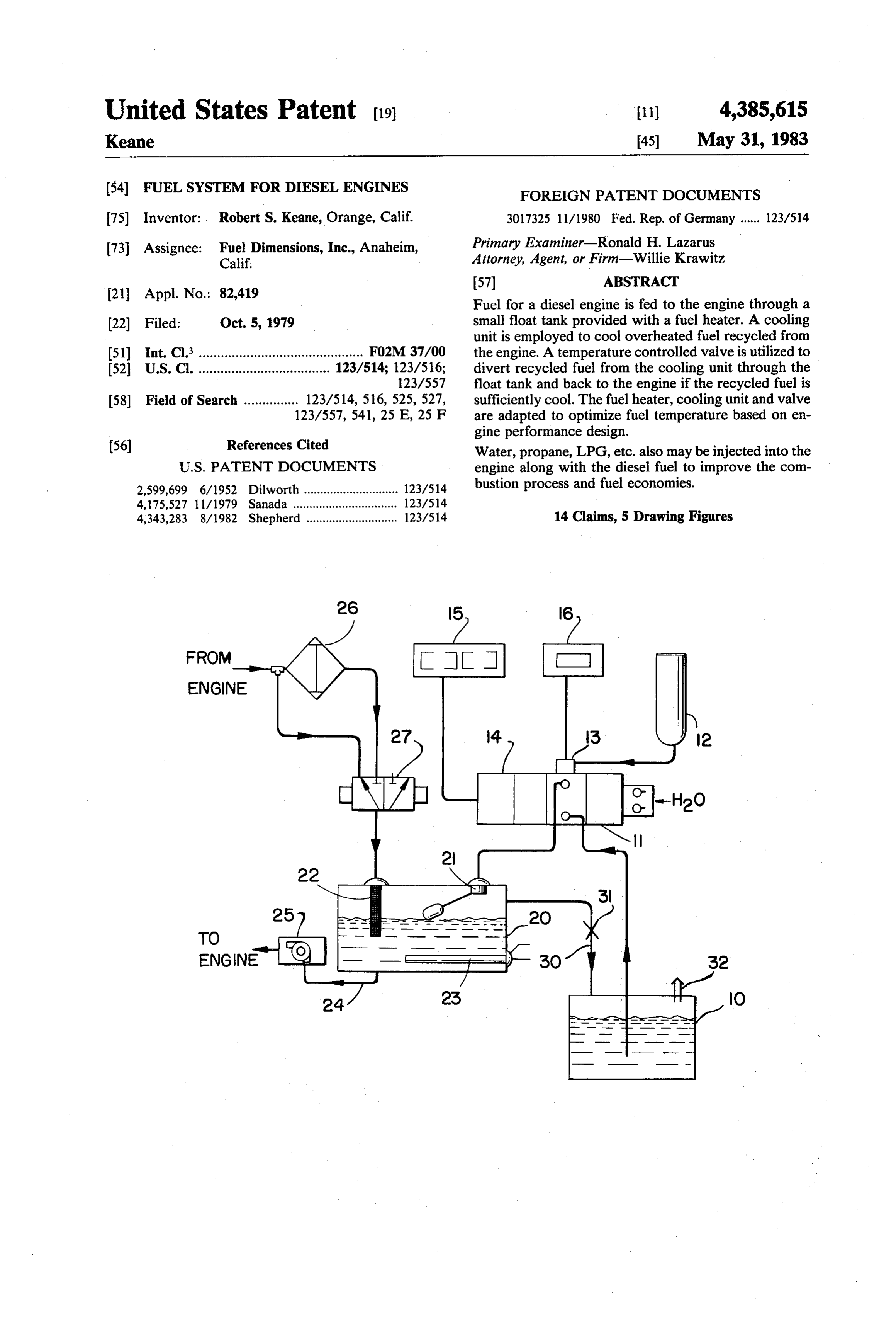
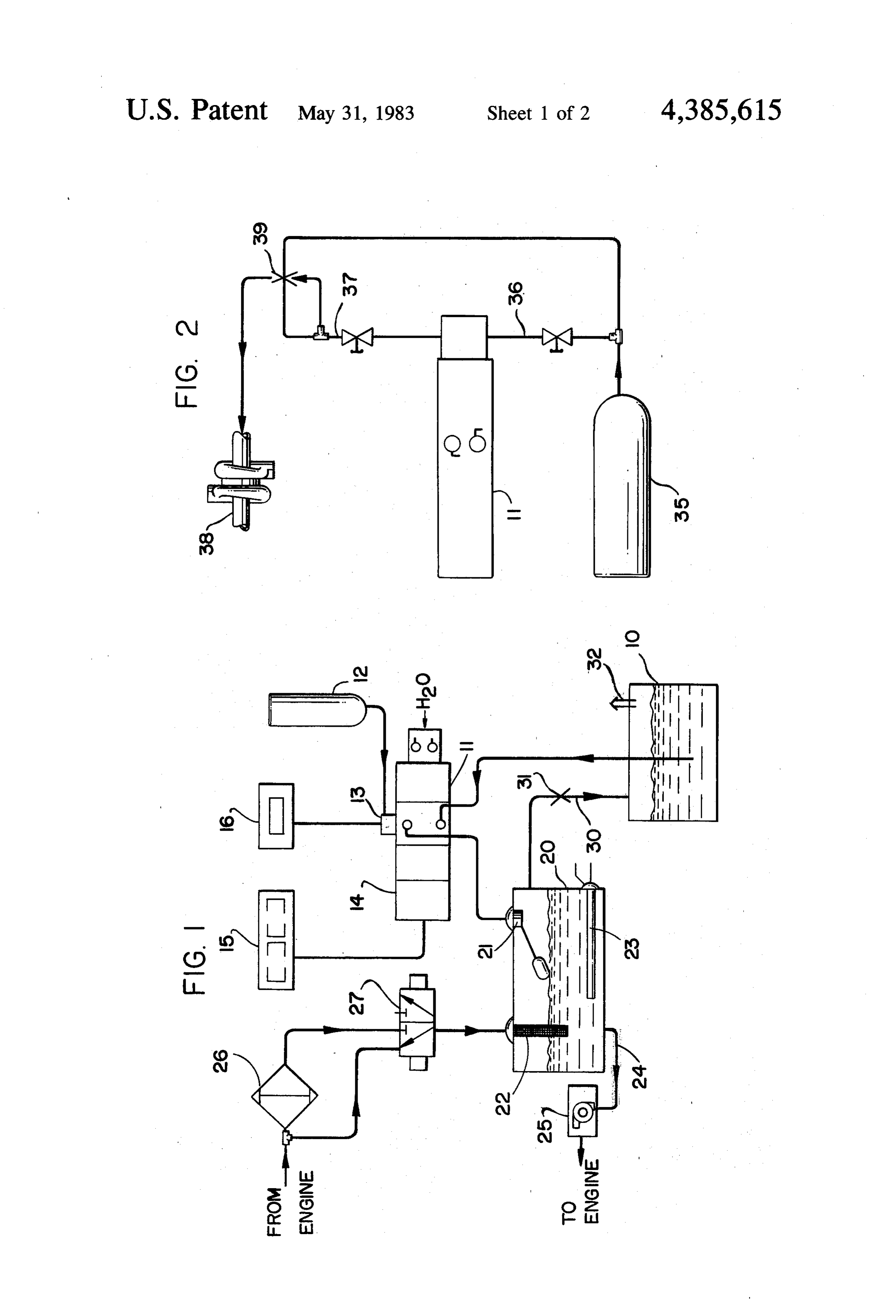
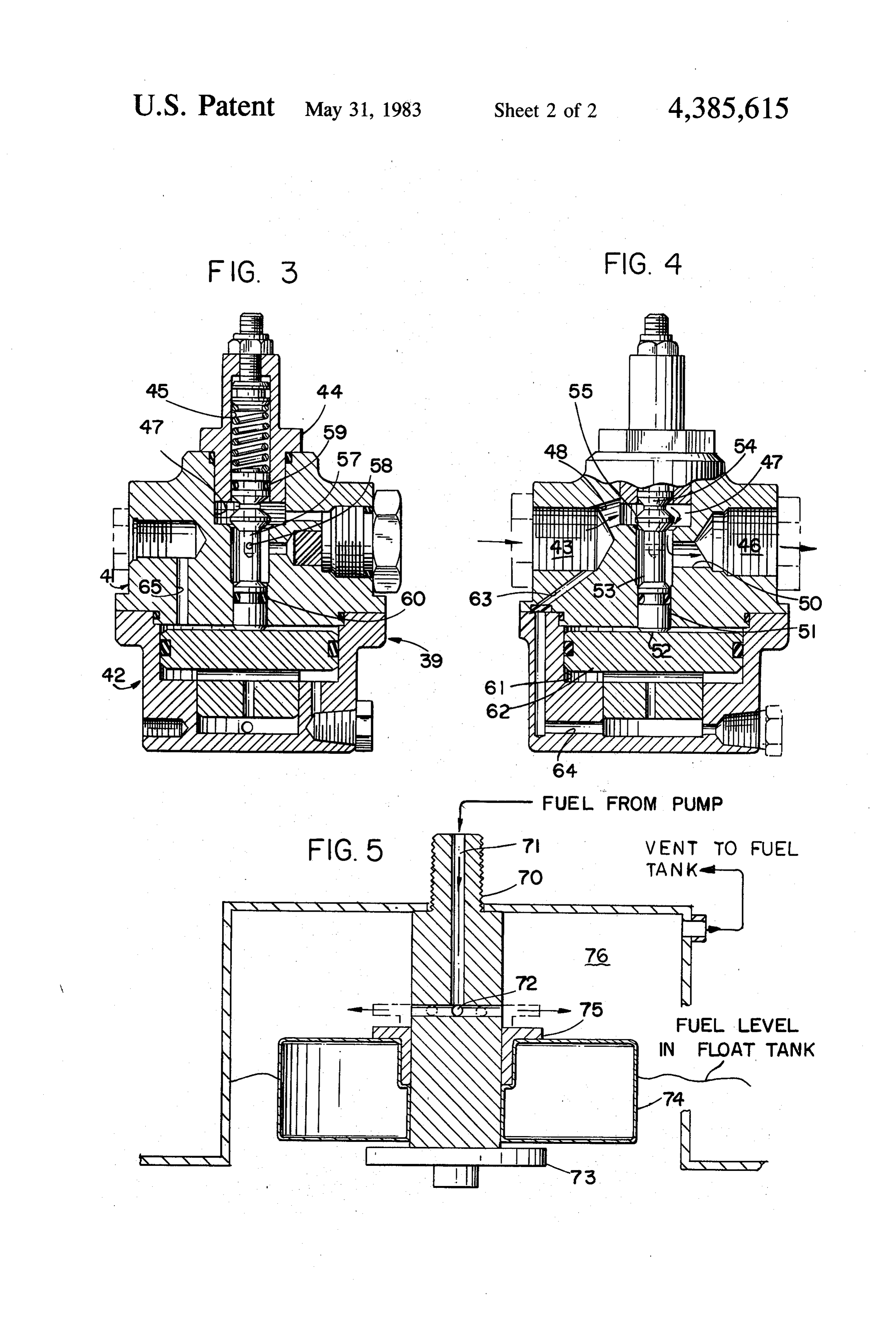
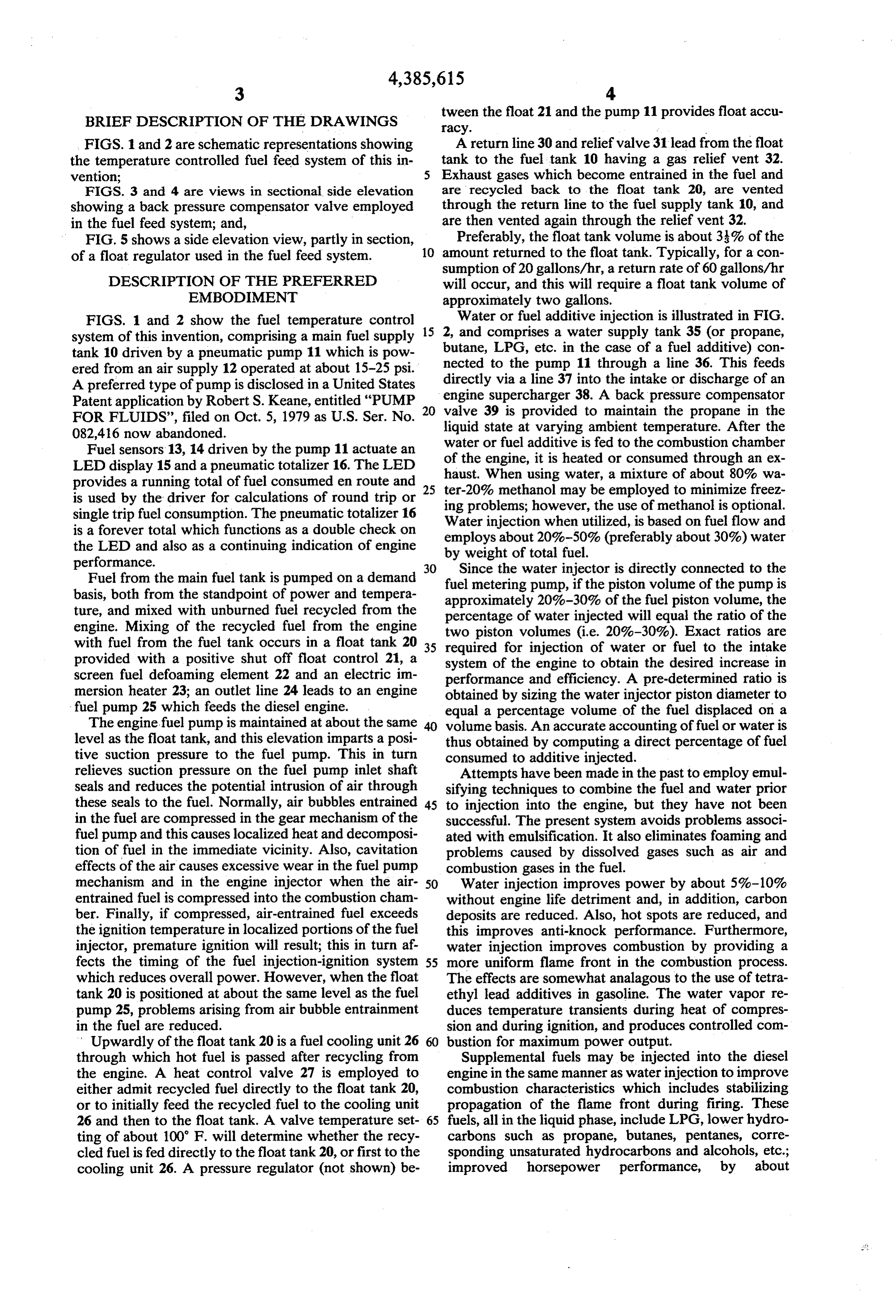
FIGS. 1 and 2 are schematic representations showing A return line 30 and relief valve 31 lead from the float the temperature controlled fuel feed system of this in tank to the fuel tank 10 having a gas relief vent 32. vention; Exhaust gases which become entrained in the fuel and FIGS. 3 and 4 are views in sectional side elevation are recycled back to the float tank 20, are vented showing a back pressure compensator valve employed through the return line to the fuel supply tank 10, and in the fuel feed system; and, are then vented again through the relief vent 32. FIG. 5 shows a side elevation view, partly in section, Preferably, the float tank volume is about 3% of the of a float regulator used in the fuel feed system. 10 amount returned to the float tank. Typically, for a con sumption of 20 gallons/hr, a return rate of 60 gallons/hr
DESCRIPTION OF THE PREFERRED will occur, and this will require a float tank volume of EMBODIMENT approximately two gallons.
FIGS. 1 and 2 show the fuel temperature control 15 Water or fuel additive injection is illustrated in FIG. system of this invention, comprising a main fuel supply 2, and comprises a water supply tank 35 (or propane, tank 10 driven by a pneumatic pump 11 which is pow butane, LPG, etc. in the case of a fuel additive) con ered from an air supply 12 operated at about 15-25 psi. nected to the pump 11 through a line 36. This feeds A preferred type of pump is disclosed in a United States directly engine via a line 37 into the intake or discharge of an supercharger 38. A back pressure compensator
Patent application by Robert S. Keane, entitled "PUMP
FOR FLUIDS', filed on Oct. 5, 1979 as U.S. Ser. No. 20 valve 39 is provided to maintain the propane in the liquid state at varying ambient temperature. After the 082,416 now abandoned. water or fuel additive is fed to the combustion chamber Fuel sensors 13, 14 driven by the pump 11 actuate an of the engine, it is heated or consumed through an ex LED display 15 and a pneumatic totalizer 16. The LED provides a running total of fuel consumed en route and 25 haust. ter-20%
When using water, a mixture of about 80% wa methanol may be employed to minimize freez is used by the driver for calculations of round trip or ing problems;
single trip fuel consumption. The pneumatic totalizer 16 Water injectionhowever, when the use of methanol is optional.
utilized, is based on fuel flow and is a forever total which functions as a double check on employs about 20%-50% (preferably about 30%) water the LED and also as a continuing indication of engine by weight of total fuel. performance. 30 Since the water injector is directly connected to the Fuel from the main fuel tank is pumped on a demand fuel metering basis, both from the standpoint of power and tempera approximatelypump, 20%-30% if the piston volume of the pump is of the fuel piston volume, the ture, and mixed with unburned fuel recycled from the percentage of water injected will equal the ratio of the engine. Mixing of the recycled fuel from the engine two piston volumes (i.e. 20%-30%). Exact ratios are with fuel from the fuel tank occurs in a float tank 20 35 required for injection of water or fuel to the intake provided with a positive shut off float control 21, a system of the engine to obtain the desired increase in screen fuel defoaming element 22 and an electric in performance and efficiency. A pre-determined ratio is mersion heater 23; an outlet line 24 leads to an engine obtained by sizing the water injector piston diameter to fuel pump 25 which feeds the diesel engine. equal a percentage volume of the fuel displaced on a The engine fuel pump is maintained at about the same volume basis. An accurate accounting of fuel or water is level as the float tank, and this elevation imparts a posi thus obtained by computing a direct percentage of fuel tive suction pressure to the fuel pump. This in turn consumed to additive injected.
relieves suction pressure on the fuel pump inlet shaft Attempts have been made in the past to employ emul seals and reduces the potential intrusion of air through sifying techniques to combine the fuel and water prior these seals to the fuel. Normally, air bubbles entrained 45 to injection into the engine, but they have not been in the fuel are compressed in the gear mechanism of the successful. The present system avoids problems associ fuel pump and this causes localized heat and decomposi ated with emulsification. It also eliminates foaming and tion of fuel in the immediate vicinity. Also, cavitation problems caused by dissolved gases such as air and effects of the air causes excessive wear in the fuel pump combustion gases in the fuel.
mechanism and in the engine injector when the air 50 Water injection improves power by about 5%-10% entrained fuel is compressed into the combustion cham without engine life detriment and, in addition, carbon ber. Finally, if compressed, air-entrained fuel exceeds deposits are reduced. Also, hot spots are reduced, and the ignition temperature in localized portions of the fuel this improves anti-knock performance. Furthermore, injector, premature ignition will result; this in turn af water injection improves combustion by providing a fects the timing of the fuel injection-ignition system 55 more uniform flame front in the combustion process. which reduces overall power. However, when the float The effects are somewhat analagous to the use of tetra tank 20 is positioned at about the same level as the fuel ethyl lead additives in gasoline. The water vapor re pump 25, problems arising from air bubble entrainment duces temperature transients during heat of compres in the fuel are reduced. sion and during ignition, and produces controlled com Upwardly of the float tank 20 is a fuel cooling unit 26 bustion for maximum power output.
through which hot fuel is passed after recycling from Supplemental fuels may be injected into the diesel the engine. A heat control valve 27 is employed to engine in the same manner as water injection to improve either admit recycled fuel directly to the float tank 20, combustion characteristics which includes stabilizing or to initially feed the recycled fuel to the cooling unit propagation of the flame front during firing. These 26 and then to the float tank. A valve temperature set 65 fuels, all in the liquid phase, include LPG, lower hydro ting of about 100 F. will determine whether the recy carbons such as propane, butanes, pentanes, corre cled fuel is fed directly to the float tank 20, or first to the sponding unsaturated hydrocarbons and alcohols, etc.; cooling unit 26. A pressure regulator (not shown) be improved horsepower performance, by about
Page 6
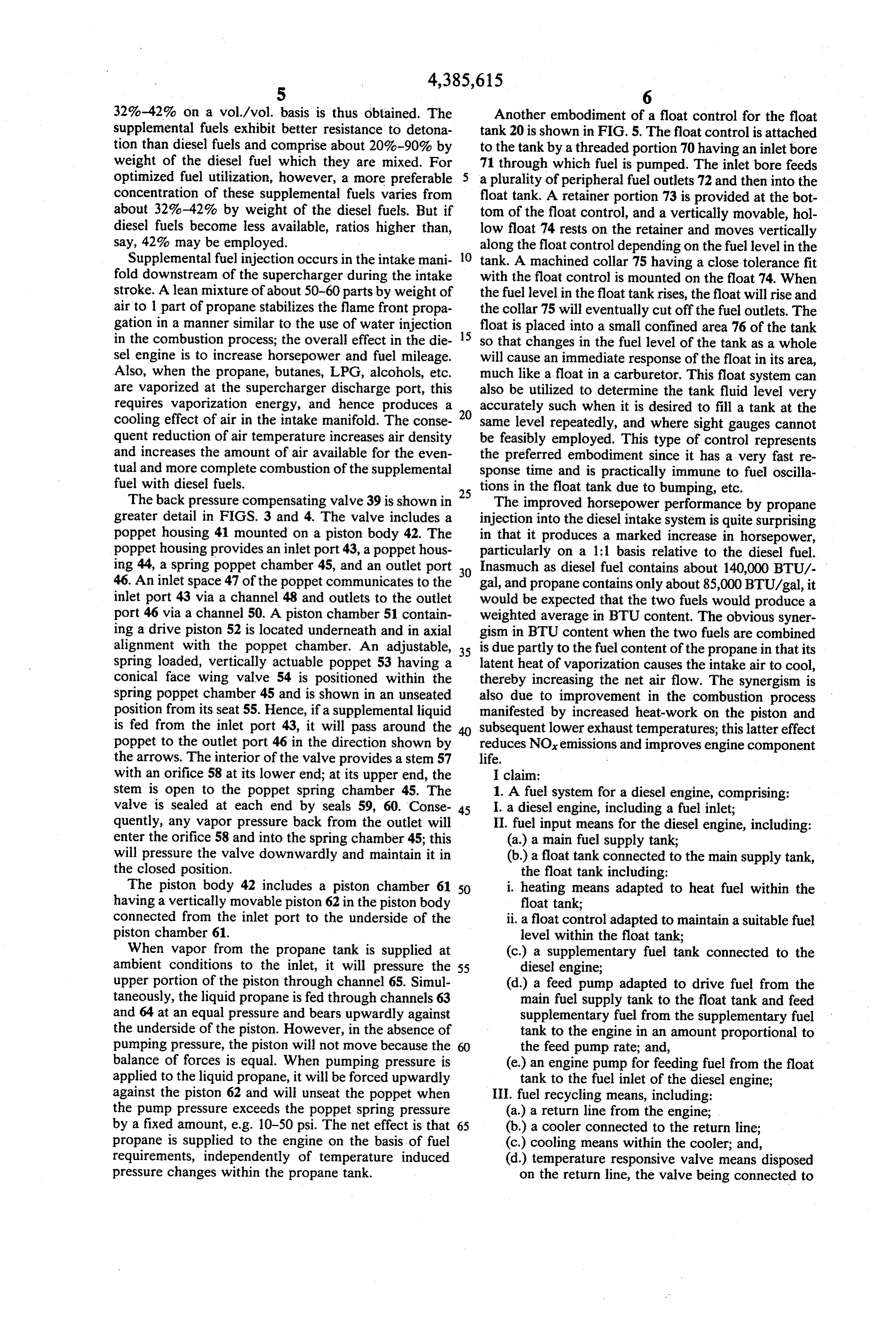
32%-42% on a vol./vol. basis is thus obtained. The Another embodiment of a float control for the float supplemental fuels exhibit better resistance to detona tank 20 is shown in FIG. 5. The float control is attached tion than diesel fuels and comprise about 20%-90% by to the tank by a threaded portion 70 having an inlet bore weight of the diesel fuel which they are mixed. For 71 through which fuel is pumped. The inlet bore feeds optimized fuel utilization, however, a more preferable a plurality of peripheral fuel outlets 72 and then into the concentration of these supplemental fuels varies from float tank. A retainer portion 73 is provided at the bot about 32%-42% by weight of the diesel fuels. But if tom of the float control, and a vertically movable, hol diesel fuels become less available, ratios higher than, low float 74 rests on the retainer and moves vertically say, 42% may be employed. along the float control depending on the fuel level in the Supplemental fuel injection occurs in the intake mani 10 tank. A machined collar 75 having a close tolerance fit fold downstream of the supercharger during the intake with the float control is mounted on the float 74. When stroke. A lean mixture of about 50-60 parts by weight of the fuel level in the float tank rises, the float will rise and air to 1 part of propane stabilizes the flame front propa the collar 75 will eventually cut off the fuel outlets. The gation in a manner similar to the use of water injection float is placed into a small confined area 76 of the tank in the combustion process; the overall effect in the die 15 so that changes in the fuel level of the tank as a whole sel engine is to increase horsepower and fuel mileage. will cause an immediate response of the float in its area, Also, when the propane, butanes, LPG, alcohols, etc. much like a float in a carburetor. This float system can are vaporized at the supercharger discharge port, this also be utilized to determine the tank fluid level very requires vaporization energy, and hence produces a accurately such when it is desired to fill a tank at the cooling effect of air in the intake manifold. The conse 20 same level repeatedly, and where sight gauges cannot quent reduction of air temperature increases air density be feasibly employed. This type of control represents and increases the amount of air available for the even the preferred embodiment since it has a very fast re tual and more complete combustion of the supplemental sponse time and is practically immune to fuel oscilla fuel with diesel fuels. tions in the float tank due to bumping, etc. The back pressure compensating valve 39 is shown in 25 The improved horsepower performance by propane greater detail in FIGS. 3 and 4. The valve includes a injection into the diesel intake system is quite surprising poppet housing 41 mounted on a piston body 42. The in that it produces a marked increase in horsepower, poppet housing provides an inlet port 43, a poppet hous particularly on a 1:1 basis relative to the diesel fuel. ing 44, a spring poppet chamber 45, and an outlet port 30 Inasmuch as diesel fuel contains about 140,000 BTU/- 46. An inlet space 47 of the poppet communicates to the gal, and propane contains only about 85,000 BTU/gal, it inlet port 43 via a channel 48 and outlets to the outlet would be expected that the two fuels would produce a port 46 via a channel 50. A piston chamber 51 contain weighted average in BTU content. The obvious syner ing a drive piston 52 is located underneath and in axial gism in BTU content when the two fuels are combined alignment with the poppet chamber. An adjustable, 35 is due partly to the fuel content of the propane in that its spring loaded, vertically actuable poppet 53 having a latent heat of vaporization causes the intake air to cool, conical face wing valve 54 is positioned within the thereby increasing the net air flow. The synergism is spring poppet chamber 45 and is shown in an unseated also due to improvement in the combustion process position from its seat 55. Hence, if a supplemental liquid manifested by increased heat-work on the piston and is fed from the inlet port 43, it will pass around the subsequent lower exhaust temperatures; this latter effect poppet to the outlet port 46 in the direction shown by reduces NOx emissions and improves engine component the arrows. The interior of the valve provides a stem 57 life.
with an orifice 58 at its lower end; at its upper end, the I claim:
stem is open to the poppet spring chamber 45. The 1. A fuel system for a diesel engine, comprising: valve is sealed at each end by seals 59, 60. Conse 45 I. a diesel engine, including a fuel inlet; quently, any vapor pressure back from the outlet will II. fuel input means for the diesel engine, including: enter the orifice 58 and into the spring chamber 45; this (a) a main fuel supply tank; will pressure the valve downwardly and maintain it in (b.) a float tank connected to the main supply tank, the closed position. the float tank including: The piston body 42 includes a piston chamber 61 50 i. heating means adapted to heat fuel within the having a vertically movable piston 62 in the piston body float tank;
connected from the inlet port to the underside of the ii. a float control adapted to maintain a suitable fuel piston chamber 61. level within the float tank; When vapor from the propane tank is supplied at (c.) a supplementary fuel tank connected to the ambient conditions to the inlet, it will pressure the 55 diesel engine;
upper portion of the piston through channel 65. Simul (d.) a feed pump adapted to drive fuel from the taneously, the liquid propane is fed through channels 63 main fuel supply tank to the float tank and feed and 64 at an equal pressure and bears upwardly against supplementary fuel from the supplementary fuel the underside of the piston. However, in the absence of tank to the engine in an amount proportional to pumping pressure, the piston will not move because the 60 the feed pump rate; and, balance of forces is equal. When pumping pressure is (e) an engine pump for feeding fuel from the float applied to the liquid propane, it will be forced upwardly tank to the fuel inlet of the diesel engine; against the piston 62 and will unseat the poppet when III. fuel recycling means, including: the pump pressure exceeds the poppet spring pressure (a) a return line from the engine; by a fixed amount, e.g. 10-50 psi. The net effect is that 65 (b.) a cooler connected to the return line; propane is supplied to the engine on the basis of fuel (c.) cooling means within the cooler; and, requirements, independently of temperature induced (d.) temperature responsive valve means disposed pressure changes within the propane tank. on the return line, the valve being connected to
Page 7
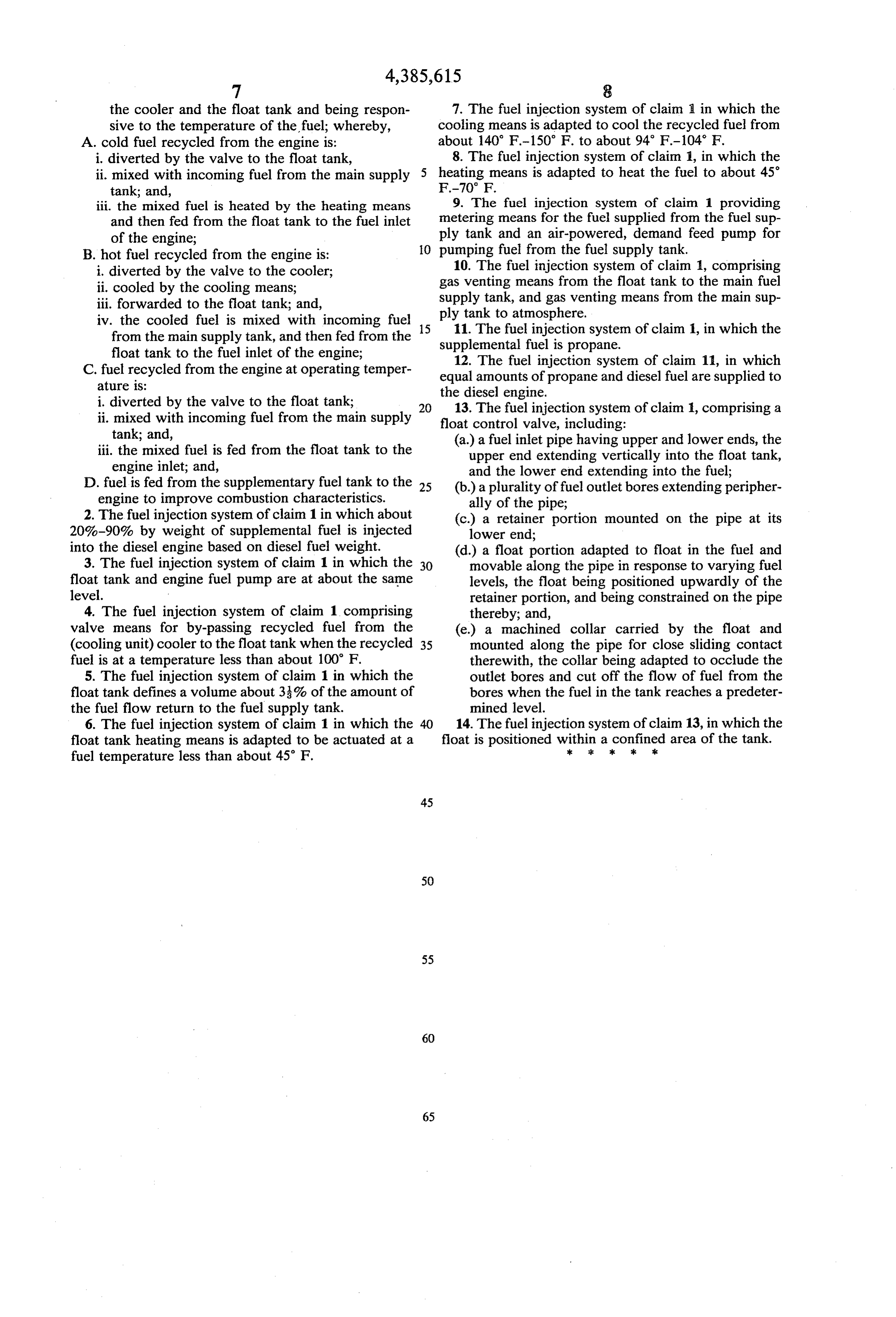
the cooler and the float tank and being respon 7. The fuel injection system of claim in which the sive to the temperature of the fuel; whereby, cooling means is adapted to cool the recycled fuel from A. cold fuel recycled from the engine is: about 140 F-150 F. to about 94 F-104 F. i. diverted by the valve to the float tank, 8. The fuel injection system of claim 1, in which the ii. mixed with incoming fuel from the main supply 5 heating means is adapted to heat the fuel to about 45° tank; and, F-70 F.
iii. the mixed fuel is heated by the heating means 9. The fuel injection system of claim 1 providing and then fed from the float tank to the fuel inlet metering means for the fuel supplied from the fuel sup of the engine; ply tank and an air-powered, demand feed pump for B. hot fuel recycled from the engine is: O pumping fuel from the fuel supply tank. i. diverted by the valve to the cooler; 10. The fuel injection system of claim 1, comprising ii. cooled by the cooling means; gas venting means from the float tank to the main fuel iii. forwarded to the float tank; and, supply tank, and gas venting means from the main sup iv. the cooled fuel is mixed with incoming fuel 15 ply11.tank The to atmosphere.
fuel injection system of claim 1, in which the from the main supply tank, and then fed from the supplemental fuel is propane.
float tank to the fuel inlet of the engine;
C. fuel recycled from the engine at operating temper equal amounts ofinjection 12. The fuel system of claim 11, in which propane and diesel fuel are supplied to ature is: the diesel engine.
i. diverted by the valve to the float tank; 13. The fuel injection system of claim 1, comprising a ii. mixed with incoming fuel from the main supply float control valve, including:
tank; and, (a.) a fuel inlet pipe having upper and lower ends, the iii. the mixed fuel is fed from the float tank to the upper end extending vertically into the float tank, engine inlet; and, and the lower end extending into the fuel; D. fuel is fed from the supplementary fuel tank to the 25 (b.) a plurality of fuel outlet bores extending peripher engine to improve combustion characteristics. ally of the pipe;
2. The fuel injection system of claim 1 in which about (c.) a retainer portion mounted on the pipe at its 20%-90% by weight of supplemental fuel is injected lower end;
into the diesel engine based on diesel fuel weight. (d.) a float portion adapted to float in the fuel and 3. The fuel injection system of claim 1 in which the 30 movable along the pipe in response to varying fuel float tank and engine fuel pump are at about the same levels, the float being positioned upwardly of the level. retainer portion, and being constrained on the pipe 4. The fuel injection system of claim 1 comprising thereby; and, valve means for by-passing recycled fuel from the (e.) a machined collar carried by the float and (cooling unit) cooler to the float tank when the recycled 35 mounted along the pipe for close sliding contact fuel is at a temperature less than about 100 F. therewith, the collar being adapted to occlude the 5. The fuel injection system of claim 1 in which the outlet bores and cut off the flow of fuel from the float tank defines a volume about 3% of the amount of bores when the fuel in the tank reaches a predeter the fuel flow return to the fuel supply tank. mined level.
6. The fuel injection system of claim 1 in which the 40 14. The fuel injection system of claim 13, in which the float tank heating means is adapted to be actuated at a float is positioned within
a kconfined
area of the tank.
fuel temperature less than about 45 F.
Provenance
- Collection
- Cited prior art
- Original PDF
- patentimages.storage.googleapis.com →
- Filed
- 1979-10-05
- Pages
- 7
- Method
- pdftotext (the PDF's own text layer) + pdftoppm 300dpi page scans
- Source
- Google Patents bibliographic record
- Granted
- 1983-05-31
- Inventors
- Robert S. Keane; FUEL DIMENSIONS Inc
- Transcribed from
- patentimages.storage.googleapis.com →