patent · US4199376
Luminescent solar collector
22 April 1980
Page 1
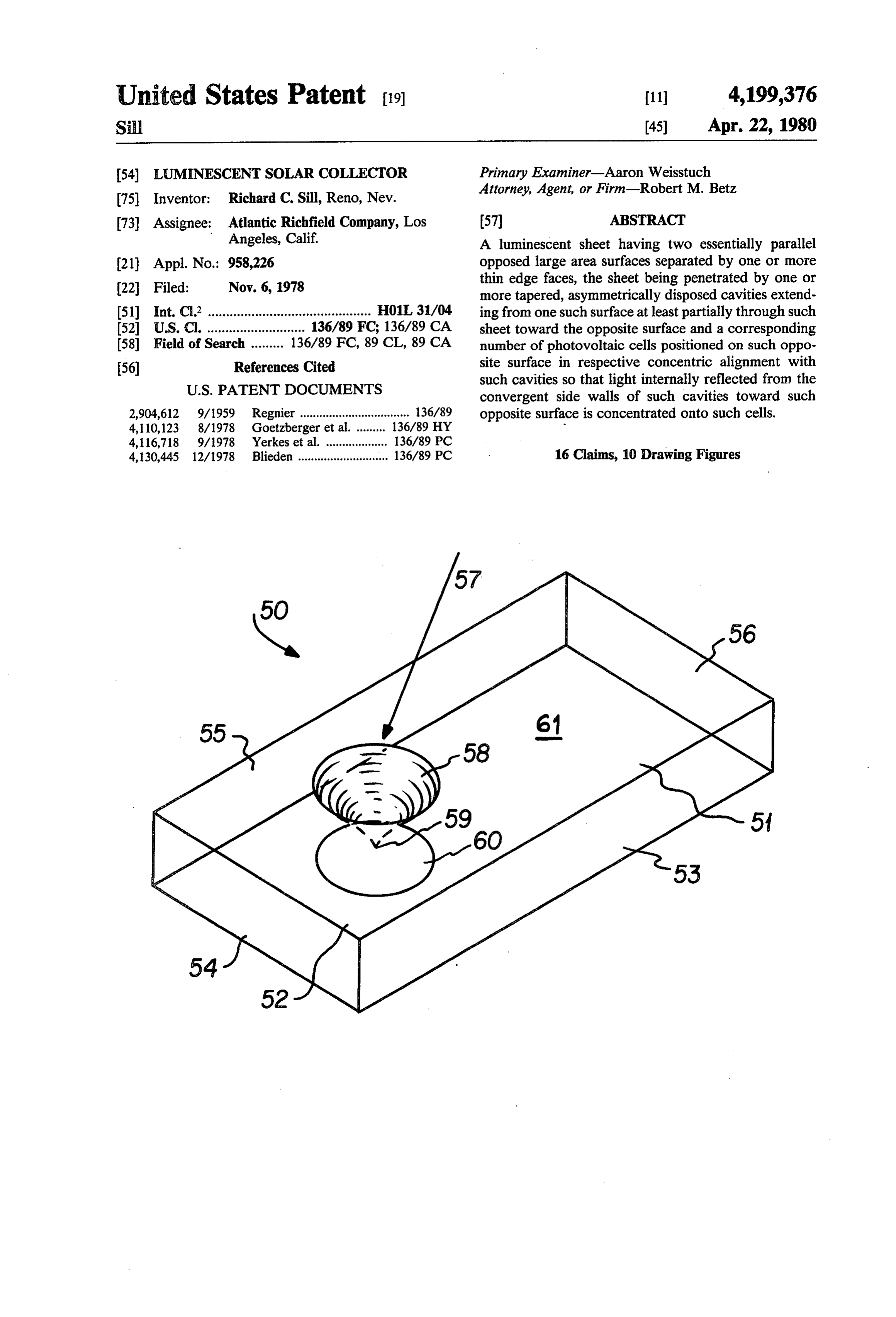
United States Patent (19) 11 4,199,376 Si 45 Apr. 22, 1980 54) LUMNESCENT SOLAR COLLECTOR Primary Examiner-Aaron Weisstuch Attorney, Agent, or Firm-Robert M. Betz (75) Inventor: Richard C. Sill, Reno, Nev.
73) Assignee: Atlantic Richfield Company, Los (57) ABSTRACT Angeles, Calif. A luminescent sheet having two essentially parallel 21 Appl. No.: 958,226 opposed large area surfaces separated by one or more
thin edge faces, the sheet being penetrated by one or more tapered, asymmetrically disposed cavities extend 51) Int. C.’............................................. H01L 31/04 ing from one such surface at least partially through such 52 U.S. Cl. ........................... 136/89 FC 136/89 CA sheet toward the opposite surface and a corresponding (58) Field of Search ......... 136/89 FC, 89 CL, 89 CA number of photovoltaic cells positioned on such oppo 56) References Cited site surface in respective concentric alignment with
convergent side walls of such cavities toward such 2,904,612 9/1959 Regnier .................................. 136/89 opposite surface is concentrated onto such cells. 4, 10,123 8/1978 Goetzberger et al. ... 136/89 HY 4, 16,718 9/1978 Yerkes et al. ......... ... 136/89 PC 4,130,445 12/1978 Blieden ............................ 136/89 PC 16 Claims, 10 Drawing Figures
Page 2
Drawing sheet — no readable text.
Page 3
Drawing sheet — no readable text.
Page 4
Drawing sheet — no readable text.
Page 5
LUMNESCENT SOLAR COLLECTOR SUMMARY OF THE INVENTION
It is therefore a general object of this invention to
BACKGROUND OF THE INVENTION provide a new and improved photovoltaic solar collec 1. Field of the Invention tor employing a luminescent sheet.
It is a more specific object of this invention to provide
This invention relates generally to apparatus for con a new and improved photovoltaic solar collector which verting solar energy to electricity by means of solar employs a thin luminescent sheet whose surface is modi cells and more particularly to apparatus of this type fied so as to utilize the light concentration characteris which more efficiently collects and concentrates avail 10 tics of such sheet in a more practical manner. able sunlight for utilization by such cells. In accordance with this invention, a luminescent 2. Description of the Prior Art sheet is at least partially penetrated by one or more It is well known that specially prepared semi-conduc tapered cavities extending inwardly from one of its two tor p-n junctions known as photovoltaic cells can con essentially parallel, opposed large area surfaces toward vertenergy from sunlight to electricity. It is also known 15 the other, such surfaces being separated by thin edge faces. A corresponding number of photovoltaic cells are that such ceils can convert to electricity only that por positioned on such other surface in alignment with such tion of the incident photon energy spectrum, typically cavities, the convergent annular side walls of such cavi solar radiation, which creates hole-electron pairs within ties being contoured so as to provide for total internal a given semi-conductor material. Photons having less 20 reflection of light energy directed toward such cells. energy than the desired spectrum are not absorbed at Other objects and advantages of this invention will all, while more energetic photons are strongly absorbed become apparent from a consideration of the detailed and wasted in heating the cell which further degrades description to follow, taken in conjunction with the its energy conversion efficiency. Thus, it is advanta figures and the appended claims.
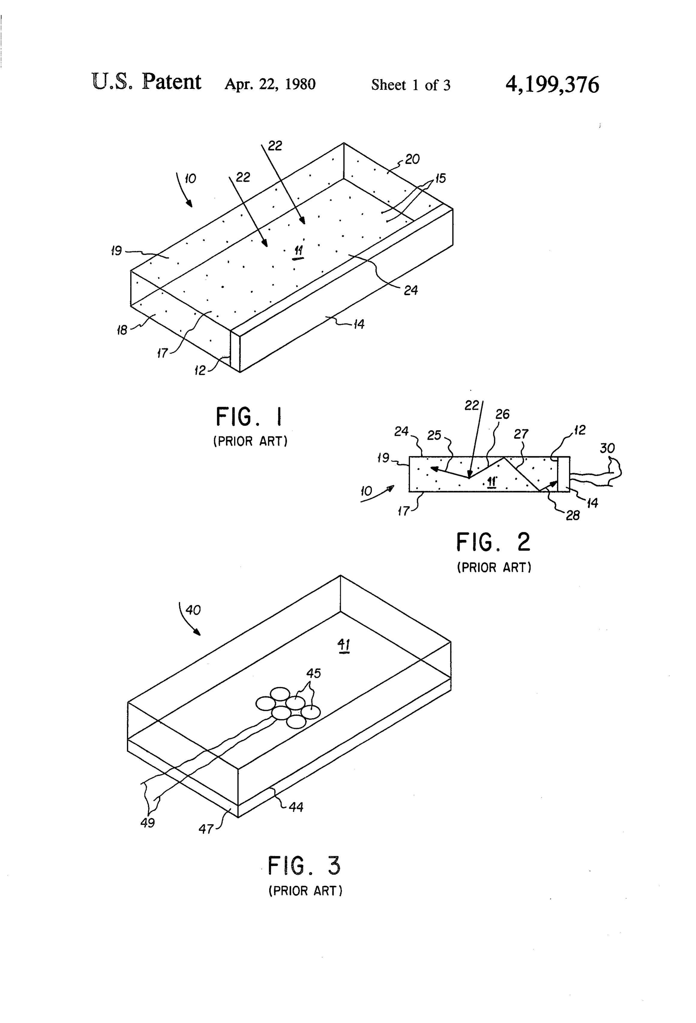
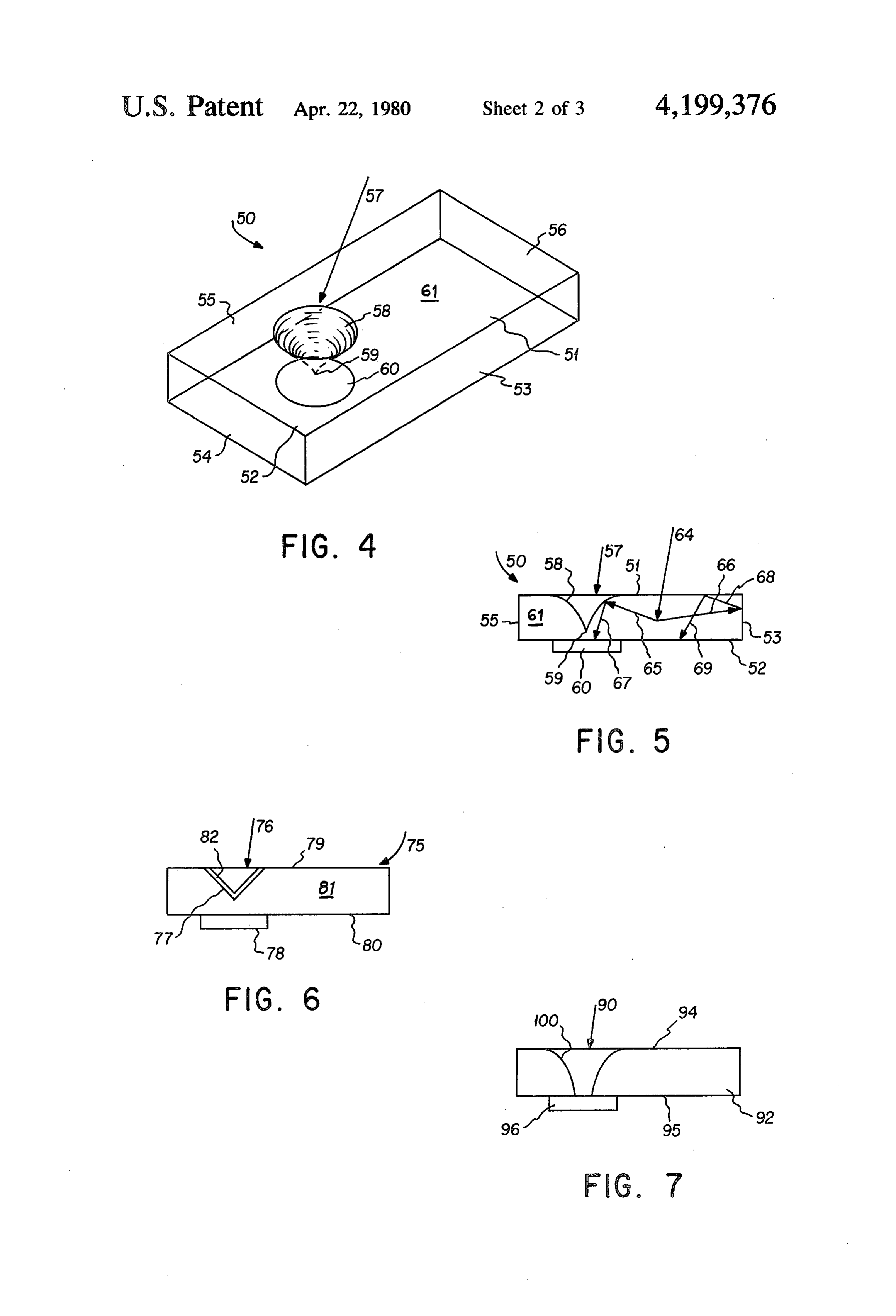
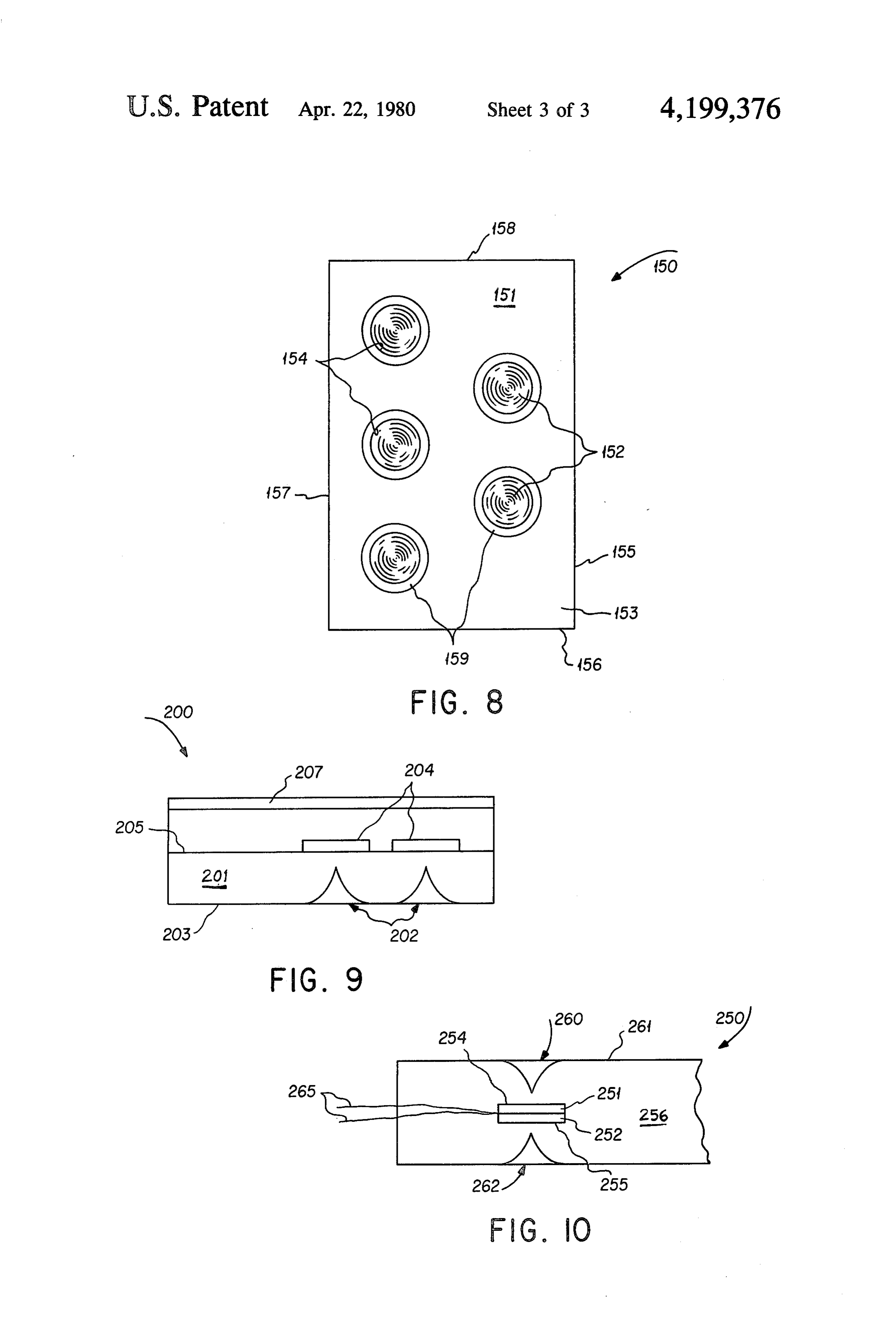
geous to convert as much of the available light as possi 25 BRIEF DESCRIPTION OF THE DRAWINGS ble into an energy spectrum to which a photovoltaic cell can usefully respond before the light strikes the FIG. 1 shows a prior art luminescent solar collector. cell's surface. FIG. 2 shows a cross-section of the device of FIG. 1. An existing technique for achieving the energy con FIG. 3 shows a prior art photovoltaic device. FIG. 4 is a device in accordance with the preferred version alluded to above takes advantage of the fact that 30 embodiment of this invention.
light falling on a luminescent material or agent is char F.G. 5 is a cross-section of the device of FIG. 4. acteristically reradiated or emitted in such a fashion as F.G. 6 is a device in accordance with an alternate to approach a narrow band of wavelengths of known embodiment of this invention.
energy content. Also light absorbed by such a material 35 FIG. 7 is a device in accordance with a further alter in one direction is scattered in many other directions. nate embodiment of this invention.
Materials or agents for this purpose include, for exam FIG. 8 is a device in accordance with a still further ple, organic dyes used in scintillation counters, lasers, embodiment of this invention.
and the like. For the purpose of this application, the FIG. 9 is a device in accordance with yet another term “luminescent agent” is understood to include ma embodiment FIG. 10 is of this invention.
a device in accordance with a still further terials exhibiting all species of luminescence, including embodiment of this invention. but not limited to fluorescence and phosphorescence.
It is shown in the literature that a dispersal of such DESCRIPTION OF THE PREFERRED luminescent materials within an internally reflective 45 EMBODIMENTS sheet or layer of transparent glass or plastic, one of FIGS. 1 and 2 show a prior art luminescent solar whose major sides or surfaces is exposed to the sun, collector 10 consisting of a planar luminescent sheet 11, concentrates and focuses a flux of light of known en one upstanding edge face 12 which is substantially cov ergy level, by successive reflections, toward one or ered by a solar cell 14. Sheet 11 is composed of a matrix more of the upstanding edge faces of such sheet. If a 50 material impregnated with one or more luminescent photovoltaic cell responsive only to light as that known agents represented diagrammatically by dots 15. The energy level is placed against or optically coupled to bottom surface 17 and the remaining three upstanding one such edge face, the energy conversion efficiency of edge faces 18, 19, and 20 may be mirrored for high the cell is increased several fold. In the present applica-. reflectance.
tion, a light transmissive sheet of such construction and 55 In accordance with the prior art teachings, a ray of properties is termed a "luminescent sheet' and a the sunlight represented by any of arrows 22 impinges on photovolatic solar collector employing such a sheet into transparent, the interior polished upper surface 24 and passes of the luminescent sheet 11. When the may be termed a "luminescent solar collector'. A lumi ray 22 impacts a luminescent agent 15, it is partially nescent solar collector of this type is fully and com 60 absorbed and re-emitted in a narrow pletely disclosed in Applied Optics, Volume 15, No. 10, efficiently usable by the photovoltaicwavelength band cell 14. This re
Pages 2299–2300, dated October 1976, the disclosure of emitted light is scattered in many directions, exempli which is incorporated by reference. fied by subrays 25 and 26 in FIG. 2, which increases the While a thin luminescent sheet of the type described probability of internal reflection. By means of succes produces a high multiplication of incident light intensity 65 sive reflections of these re-emitted subrays, such as on an edge mounted solar cell, such an arrangement is exemplified by subrays 27 and 28, it has been established impractical for solar cells of conventional design and that an intense flux of light at the desired wavelength is S12. funneled to the edge 12 where it impinges on the photo
Page 6
cell 14 and stimulates the desired energy conversion. energy absorbing internal reflections within the sheet The electricity generated can be coupled into a useful 61. If edge faces 53 through 56 are made suitably reflec load by means of conductors 30. tive, the energy of subray 66 is redirected and retained In order to attach a photovoltaic cell of conventional within the sheet 61 as by subrays 68 and 69 until ulti design and size to the edge face 12, the edge faces 12, 18, mately such redirected energy also reaches internally 19, and 20 of luminescent sheet 11 must be made rela reflective side wall 58. In the manner described, there tively thick with respect to the area of large area sur will be a concentration of light energy toward the faces 17 and 24. This of course directly increases the downwardly convergent wall 58 on all sides substan cost of sheet 11 per unit area. Furthermore, for a large tially paralleling the surfaces 51 and 52. By positioning area luminescent sheet 11, subrays such as 25through 28 10 a cell 60 directly in the path of light energy internally will have to traverse so much of the body of sheet 11 in reflected from the wall 58, the cell 60 becomes preferen order to reach cell 14 that a substantial part of the light tially responsive to such reflected energy and receives in the desired energy spectrum will be absorbed prior to an intensely concentrated light flux. Thus the cavity 57 reaching cell 14. The invention to be described makes it may be said to act as a "light sink’ or trap for sunlight possible to employ a relatively thin luminescent sheet 5 incident over the surface 51. The introduction of cavity by modifying the sheet itself and repositioning the asso 57 is now seen in effect to take direct advantage of the ciated photovoltaic cells. edge concentration effect in a luminescent sheet while FIG. 3 shows a conventional superstrate prior art permitting the energy receiving photo voltaic cell 60 to photovoltaic solar collector 40 which does not employ be positioned on the conveniently large area surface 52. luminescent enhancement. The device consists of an 20 The shape of the plane curve of wall 58 which gener upper light transmitting member 41 of transparent mate ates the total surface thereof and which is defined by a rial which may be polymeric or glass or similar material vertical section through sheet 61 may be varied by the and which may carry cn its underside 44 a plurality of designer as a matter of choice depending on the desired photovoltaic cells 45 having a moisture barrier layer 47 distribution of reflected energy reaching cell 68. For thereunder which may be also composed of transparent 25 example, in FIGS. 4 and 5 this curve may take the form material. Electrical leads 49 may be interconnected of a downwardly concave generator such as a parabola with cells 45 as shown. A device such as shown in FIG. or hyperbola. With a continuously varying slope for 3 does not suffer from the disadvantage of the prior art wall 58 reflection therefrom of light paralleling surfaces device of FIG. 1 in that adequate space is now provided 51 and 52 will be distributed over an area of cell 60 with for photovoltaic cells 45 of any desired size. However, 30 varying intensity. If desired, one may apply external such a device lacks the edge-directed light concentra reflective means (not shown) to wall 58, but within the tion characteristics of a luminescent sheet. The present skill of this art one may curve wall 58 so that it produces invention combines the practical advantage of mount substantially total internal light reflection within the ing photovoltaic cells on a large area surface of a trans sheet 61 without such external reflective means. Con parent superstrate with the light concentration ability of 35 versely, as in the embodiment of FIG. 6, one may pro a luminescent sheet by providing the sheet with interior vide a luminescent collector 75 comprising luminescent optical surfaces which effectively concentrate and sheet 81 with a cavity 76 having a side wall 77 formed focus light energy toward such ceils. from a straight line generatorso as to produce a cone. In Referring now to FIGS. 4 and 5, there is shown a this case, energy internally reflected from such wall 77 luminescent solar collector 50 in accordance with this 40 tends to distribute itself uniformly over the area of pho invention. In these and subsequent figures illustrating tovoltaic cell 78. However, for efficient internal reflec luminescent sheets the representation of internal lumi tion wall 77 should not exceed an angle of 45 to the nescent agents has been omitted for clarity. A lumines plane of surfaces 79 and 80 and should be provided with cent sheet 61 includes a pair of opposed essentially external silvering 82 or other reflective means. parallel large area surfaces 51 and 52 joined by thin 45 As shown in the additional alternate embodiment of upstanding edge faces 53, 54, 55 and 56, the cross-sec this invention in FIG. 7, the cavity 90 in a luminescent tional area of sides 53 through 56 being small relative to sheet 92 may penetrate completely through from the the area of sides 51 and 52. Within the scope of this upper sun light receiving surface 94 to the lower surface invention the sheet 61 in plan may assume any other 95 on which is carried photovoltaic cell 96. As indicated desired outline, such as circular, hexagonal, etc. 50 above, the side wall 100 of cavity 90 may be given any The luminescent sheet 61 is provided with one or desired downwardly concave or other shape. The more tapered cavities 57 penetrating the upper surface mechanism of direct light energy reflection from the 51 and extending at least partially through the thickness internal surface of wall 100 to cell 96 is the same as of sheet 61 toward the lower surface 52. As shown in previously described, except that no reflected energy FIGS. 4 and 5, cavity 57 preferably defines a surface of 55 reaches the central portion of the cell 96. revolution whose optically smooth annular side wall 58 In a practical device in accordance with this inven tapers and converges to apex 59. Coupled to the surface tion, it will be advantageous to degrade strict adherence 52 is a corresponding photovoltaic cell 60 positioned in to a perfectly square or other geometric shape for the general alignment with the axis of cavity 57 so that the luminescent shelt and to avoid symmetric placement of energy-receiving surface of the cell 60 faces and lies 60 its internally reflective cavity. Thus, for example, in directly beneath the smoothly contoured side wall 58 of FIG. 4, one may cut faces 53 through 56 at other than cavity 57. ninety degree angles and offset cavity 57 toward one Asbest seen in FIG. 5, a ray of sunlight 64 incident on edge face 55. This will tend to minimize standing modes sheet 61 penetrates the surface 51 and impinges on lumi or repetitive edge-to-edge light reflections which miss nescent material therein so as to be re-emitted, for exam 65 the cavity 57, producing heat but no useful energy out ple, in the form of subrays 65 and 66. Subray 65, upon put.
reaching the contoured surface 58, is reflected as subray In the alternate embodiment of FIG. 8, a luminescent 67 directly to the surface of the cell 60 without further collector 150 comprising luminescent sheet 151 is
Page 7
shown in plan with an array of tapered cavities 152 of the luminescent sheets on which the photovoltaic extending downwardly from upper surface 153. It will cells are carried in areas adjacent the interfaces with be understood that a corresponding array of photovol such cells, thus further enhancing internal reflection taic cells A59 may be disposed in one-to-one correspon and retention of light energy.
dence and alignment with the cavities 152 on the bot 5 It will be understood that, while the foregoing de tom surface (not shown) of the sheet 51. The mecha scription and drawings are illustrative of preferred em nism of internal reflection from the respective side walls bodiments of this invention, those skilled in the art will 154 of cavities 152 is identical to that previously de have no difficult in devising further modification in the scribed. The plan view of FIG. 8, however, illustrates a configuration and arrangement of component parts deliberately asymmetric placement of cavities 152 with 10 without departing from the scope of this invention as set respect to the edges 155-158 of sheet 151, thus avoiding forth in the claims appended hereto. energy losses due to repetitive edge-to-edge reflections. I claim:
In yet another embodiment of this invention as seen in 1. A luminescent solar collector comprising a lumi FIG.9, a luminescent collector 200 comprising lumines nescent sheet having first and second essentially parallel cent sheet 202 is provided with upwardly tapering cavi 15 opposed large area surfaces separated by at least one ties 202 on its bottom surface 203, corresponding photo thin edge face, said sheet being provided with at least voltaic cells 204 being carried on its upper surface 205. one thin edge face, said sheet being provided with at An environmental shield 207 may be positioned over least one cavity having an inwardly converging tapered the cells 204. The cavities 202 internally reflect edge annular side wall penetrating said first surface and ex concentrated light energy towards their respective cells 20 tending therefrom at least partially through such sheet 204 in the manner previously described for other em toward said second surface, said side wall being con bodiments.
Finally, within the scope of this invention, as seen in toured sheet is so that light energy incident thereon within said internally reflected toward said second surface,
FIG. 10, one may employ a luminescent collector 250 and a photovoltaic means supported in fixed relation comprising luminescent sheet 256 within which are adjacent the convergent
end of each said cavity so as to embedded pairs of photovoltaic cells such as cells 251 receive said reflected energy.
and 252 interconnected so that their respective energy 2. A device according to claim 1 wherein said photo receiving surfaces 254 and 255 face in opposite direc voltaic means is coupled to said second surface. tions. In the manner previously described, the wall of cavity 260 penetrating the upper sun light receiving 30 3. A device according to claim 1 wherein said side surface 261 of the sheet 256 internally reflects concen wall of said cavity is a surface of revolution having an trated light energy onto the surface 254 of the cell 251. axis4. normal
to said first and second surfaces.
device according to claim 3 wherein said photo
In similar fashion, the wall of cavity 262 extending upwardly from the bottom surface 263 of the sheet 256 axisvoltaic means is a photovoltaic cell concentric with the enhances internal light reflections onto the energy 35 5. of A said surface of revolution.
device according to claim 3 wherein said cavity receiving surface 255 of cell 252. Electrical leads 265 is tapered in the direction of said second surface. may be brought in between cells 251 and 252 and inter 6. A device according to claim 5 wherein the genera connected with an external load.
The luminescent sheets down in FIGS. 4 through 10 tor of said surface of revolution is a straight line. may be made of glass or polymeric material or other 7. A device according to claim 5 wherein the genera transparent material into which luminescent agents can tor of said surface of revolution is a curve. be incorporated and dispersed by well known means, so 8. A device according to claim 7 wherein said surface long as the matrix material can be cast, molded, or cut of revolution is concave with respect to light incident into the indicated geometric shapes. The luminescent thereon within said sheet. materials may include commercially available metals, 45 9. A device according to claim 1 wherein said at least oxides, or other metallic compounds whose characteris one cavity extends partially through said sheet. tics are well known to the art. Such materials include, least10. A device according to claim 1 wherein said at for example, neodymium oxide in a glass matrix or laser one cavity extends completely through such sheet. dyes from the coumarin or rhodamine families. Within 11. A device according to claim 1 wherein said lumi the scope of this invention, the luminescent agents em 50 nescent sheet has an irregular shape. ployed may either emit light directly or by way of cas 12. A device according to claim 1 wherein said sheet cading which approaches the desired energy range for contains a plurality of said cavities in spaced apart rela specific types of photovoltaic cells. tion, each of said cavities having a photovoltaic means Photovoltaic cells which may be used in the practice. positioned adjacent its convergent end. of this invention may include silicon, cadmium sulfide, 55 i3. A device according to claim 1 wherein said edge gallium arsenide and many other semi-conductor mate face is totally reflective.
rials well known to the art. The photovoltaic cells to be 14. A device according to claim 1 wherein said side employed in this invention are not limited as to size or wall of said at least one cavity is provided with external shape or configuration. Any suitable adherent means reflective means.
are acceptable for applying the cells to the large area 60 15. A device according to claim 1 wherein said pho surfaces of the various luminescent sheets. The interface tovoltaic means is embedded within said luminescent between the luminescent sheets and the photovoltaic sheet.
cells may be any optically clear material whose index of 16. A device according to claim 1 wherein said sec refraction is close to that of the luminescent sheet. It ond surface is provided with diffuser means adjacent to may also include an anti-reflective coating. 65 the interface between said photovoltaic means and said It may be desirable within the scope of this invention sheet.
to roughen or add light diffusive material to the surfaces
Provenance
- Collection
- Cited prior art
- Original PDF
- patentimages.storage.googleapis.com →
- Filed
- 1978-11-06
- Pages
- 7
- Method
- pdftotext (the PDF's own text layer) + pdftoppm 300dpi page scans
- Source
- Google Patents bibliographic record
- Granted
- 1980-04-22
- Inventors
- Richard C. Sill; Atlantic Richfield Co
- Transcribed from
- patentimages.storage.googleapis.com →