patent · US4188238
Generation of electrical energy from sunlight, and apparatus
12 February 1980
Page 1 — bibliographic record
United States Patent (19) 11) 4,188,238 Boling 45) Feb. 12, 1980 (54). GENERATION OF ELECTRICAL ENERGY FOREIGN PATENT DOCUMENTS
FROM SUNLIGHT, AND APPARATUS
75 Inventor: Norman L. Boling, Toledo, Ohio Primary Examiner-Aaron Weisstuch 73) Assignee: Owens-Illinois, Inc., Toledo, Ohio Attorney, Agent, or Firm-Charles S. Lynch; M. E. Click; D. H. Wilson 21 Appl. No.: 921,419 57 ABSTRACT (22 Filed: Jul. 3, 1978 Disclosed is a process and apparatus for concentrating sunlight optically and impinging the concentrated light
Sll Int. Cl’............................................. HO1L 31/04 on at least one luminescent solar collector coupled to a 52 U.S. C. ................................................ 136/89 FC first photocell, passing residual concentrated sunlight to at least one other luminescent solar collector in one (58) Field of Search .......... 136/89 PC, 89 HY, 89 FC embodiment, coupled to a different photocell, and fi 56) References Cited nally passing the remaining concentrated sunlight di rectly to a still different photocell.
4,110,123 8/1978 Goetzberger et al. ................ 136/89 7 Claims, 5 Drawing Figures
Page 2
Drawing sheet — no readable text.
Page 3
Drawing sheet — no readable text.
Page 4
GENERATION OF ELECTRICAL ENERGY FROM "fixed' in layers of a silicone resin superimposed on the
The present invention in a unique arrangement uti
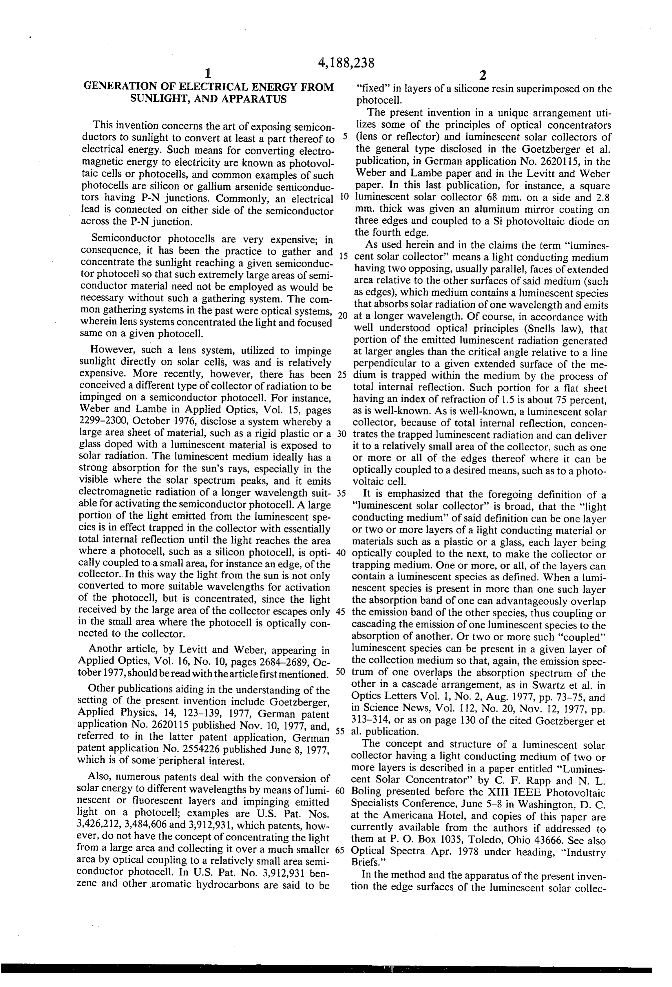
This invention concerns the art of exposing semicon lizes some of the principles of optical concentrators ductors to sunlight to convert at least a part thereof to (lens or reflector) and luminescent solar collectors of electrical energy. Such means for converting electro the general type disclosed in the Goetzberger et al. magnetic energy to electricity are known as photovol publication, in German application No. 2620115, in the taic cells or photocells, and common examples of such Weber and Lambe paper and in the Levitt and Weber photocells are silicon or gallium arsenide semiconduc O paper. In this last publication, for instance, a square tors having P-N junctions. Commonly, an electrical luminescent solar collector 68 mm. on a side and 2.8 lead is connected on either side of the semiconductor mm. thick was given an aluminum mirror coating on across the P-N junction. three edges and coupled to a Si photovoltaic diode on Semiconductor photocells are very expensive; in theAsfourth edge.
used herein and in the claims the term "lumines consequence, it has been the practice to gather and 15 cent solar collector' means a light conducting medium concentrate the sunlight reaching a given semiconduc having two opposing, usually parallel, faces of extended tor photocell so that such extremely large areas of semi area relative to the other surfaces of said medium (such conductor material need not be employed as would be as edges), which medium contains a luminescent species necessary without such a gathering system. The com that absorbs solar radiation of one wavelength and emits mon gathering systems in the past were optical systems, 20 wherein lens systems concentrated the light and focused atwella longer wavelength. Of course, in accordance with understood optical principles (Snells law), that same on a given photocell. portion of the emitted luminescent radiation generated However, such a lens system, utilized to impinge at larger angles than the critical angle relative to a line sunlight directly on solar cells, was and is relatively perpendicular to a given extended surface of the me expensive. More recently, however, there has been 25 dium is trapped within the medium by the process of conceived a different type of collector of radiation to be total internal reflection. Such portion for a flat sheet impinged on a semiconductor photocell. For instance, having an index of refraction of 1.5 is about 75 percent, Weber and Lambe in Applied Optics, Vol. 15, pages as is well-known. As is well-known, a luminescent solar 2299-2300, October 1976, disclose a system whereby a collector, because of total internal reflection, concen large area sheet of material, such as a rigid plastic or a 30 trates the trapped luminescent radiation and can deliver glass doped with a luminescent material is exposed to it to a relatively small area of the collector, such as one solar radiation. The luminescent medium ideally has a or more or all of the edges thereof where it can be strong absorption for the sun's rays, especially in the optically coupled to a desired means, such as to a photo visible where the solar spectrum peaks, and it emits voltaic cell.
electromagnetic radiation of a longer wavelength suit 35 It is emphasized that the foregoing definition of a able for activating the semiconductor photocell. A large "luminescent solar collector" is broad, that the "light portion of the light emitted from the luminescent spe conducting medium' of said definition can be one layer cies is in effect trapped in the collector with essentially or two or more layers of a light conducting material or total internal reflection until the light reaches the area materials such as a plastic or a glass, each layer being where a photocell, such as a silicon photocell, is opti 40 optically coupled to the next, to make the collector or cally coupled to a small area, for instance an edge, of the trapping medium. One or more, or all, of the layers can collector. In this way the light from the sun is not only contain a luminescent species as defined. When a lumi converted to more suitable wavelengths for activation nescent species is present in more than one such layer of the photocell, but is concentrated, since the light the absorption band of one can advantageously overlap received by the large area of the collector escapes only 45 the emission band of the other species, thus coupling or in the small area where the photocell is optically con cascading the emission of one luminescent species to the nected to the collector. absorption of another. Or two or more such "coupled' Anothr article, by Levitt and Weber, appearing in luminescent species can be present in a given layer of Applied Optics, Vol. 16, No. 10, pages 2684-2689, Oc the collection medium so that, again, the emission spec tober 1977, should be read with the article first mentioned. 50 trum of one overlaps the absorption spectrum of the Other publications aiding in the understanding of the Optics other in a cascade arrangement, as in Swartz et al. in setting of the present invention include Goetzberger, Letters Vol. 1, No. 2, Aug. 1977, pp. 73-75, and Applied Physics, 14, 123-139, 1977, German patent in313-314, Science News, Vol. 112, No. 20, Nov. 12, 1977, pp. or as on page 130 of the cited Goetzberger et application No. 2620115 published Nov. 10, 1977, and, referred to in the latter patent application, German 55 al.The publication.
patent application No. 2554226 published June 8, 1977, collectorconcept and structure of a luminescent solar having a light conducting medium of two or which is of some peripheral interest. more layers is described in a paper entitled "Lumines Also, numerous patents deal with the conversion of cent Solar Concentrator" by C. F. Rapp and N. L. Solar energy to different wavelengths by means of lumi 60 Boling presented before the XIII IEEE Photovoltaic nescent or fluorescent layers and impinging emitted Specialists Conference, June 5-8 in Washington, D. C. light on a photocell; examples are U.S. Pat. Nos. at the Americana Hotel, and copies of this paper are 3,426,212, 3,484,606 and 3,912,931, which patents, how currently available from the authors if addressed to ever, do not have the concept of concentrating the light them at P. O. Box 1035, Toledo, Ohio 43666. See also from a large area and collecting it over a much smaller 65 Optical Spectra Apr. 1978 under heading, “Industry area by optical coupling to a relatively small area semi Briefs.'
conductor photocell. In U.S. Pat. No. 3,912,931 ben In the method and the apparatus of the present inven Zene and other aromatic hydrocarbons are said to be tion the edge surfaces of the luminescent solar collec
Page 5
tors not coupled to a photovoltaic cell have a highly perhaps the length of a side can be 50 to 100 cm. or a reflective coating to prevent escape of trapped lumines little more.
cent radiation at such edges, as will be understood. When an optical concentrator of sunlight (lens or It is an object of the present invention to improve the mirror) is used to impinge concentrated solar radiation process of generating electrical energy by impinging on a photocell, almost any concentration factor can be electromagnetic radiation derived from sunlight on achieved. However, the solar cell receives all wave photovoltaic cells, both from the viewpoint of effi lengths, but an appreciably large portion of the solar ciency and of economics. energy, especially of very short and very long wave It is another object of the invention to provide a lengths is converted to heat by many photocells, in unique arrangement or combination of apparatus for O creasing the amount of cell cooling needed per watt such process. when compared with luminescent solar collectors. Other objects, as well as aspects and advantages, of As noted, the method of producing electricity by the invention will become apparent from a study of this optically concentrating sunlight and impinging it di specification. rectly on solar cells is expensive. One reason is that According to a first important aspect of the present 15 existing practical semiconductor photocells are respon invention, I provide a process (and an arrangement of sive only to a portion of the sun's rays to produce elec apparatus) wherein the ease of concentrating sunlight tricity with efficiency. Thus, with most photocells optically is combined with the ability of luminescent wavelengths in the ultraviolet and in some cases the low solar collectors not only to concentrate but also to spec end of the infrared are only partly converted to electric trally divide the optically concentrated radiation, 20 ity and much of the energy is converted to heat. As the which process comprises wavelength absorbed approaches the bandgap wave (1) concentrating solar radiation optically with lens length the proportion of energy converted to heat is or reflector means to provide optically concen decreased, cell heating problems are decreased, and the trated radiation and efficiency of conversion of the radiation to electrical (2) spectrally dividing said optically concentrated 25 energy is increased. However, when sunlight is directly radiation by impinged on a photocell (whether or not after concen (i) absorbing a portion of said concentrated radiation trating with a lens or mirror), all wavelengths are re and concentrating absorbed radiation in the form of ceived and a great portion of the radiant energy is not longer wavelength emitted luminescent radiation utilized to generate electricity; moreover, a great por by the process of total internal reflection in a first 30 tion of the lost energy is converted to heat that must be luminescent solar collector, removed lest the cells become too hot. Thus, photons (ii) passing the residual portion of said optically con having much higher energy than the bandgap of a given centrated radiation through said first luminescent photocell lose a great deal of the absorbed energy as solar collector and, optionally, repeating steps (i) heat, and absorbed photons having lower energy pro and (ii) using one or more subsequent luminescent 35 duce no electricity and are almost entirely converted to solar collectors in series acting on the residual opti heat.
cally concentrated radiation passing through the An advantage of the present apparatus and process is preceding luminescent solar collector, that the sunlight can be concentrated largely optically (3) passing the concentrated emitted luminescent (lens or mirror), yet only the desired wavelengths (ob radiation in said first collector to a first photovoltaic 40 tained by choice of the one or more luminescent spe cell optically coupled to a relatively small surface area cies) need be delivered to the photocell, so that heating of said first luminescent solar collector and passing the of the solar cell is minimized. Moreover, the lumines concentrated emitted luminescent radiation in each said cent solar collectors can be quite small since a very subsequent luminescent solar collector, if any, to a dif large proportion of the concentrating of the solar radia ferent photovoltaic cell having a different bandgap than 45 tion has been done by the time that the solar radiation is said first cell, which different cell is optically coupled to delivered to the luminescent solar collector. Because of a relatively small surface area of the subsequent lumi the small size of the matrix or host material the lumines nescent solar collector, and cent solar collector medium need not exhibit such ex (4) impinging the residual optically concentrated tremely low absorption losses. On the other hand, such radiation directly on a still different photovoltaic cell SO matrix material can be a high index of refraction mate responsive to at least a portion of said residual radiation. rial even though such materials be expensive, since it is In the process and apparatus of the invention the used in relatively small amounts, and one can afford the optical means for concentrating sunlight (mirror or best treatment thereof such as the best antireflection lens) is focused on a surface of extended area of a lumi coatings and high quality mirroring of edges, all of nescent solar collector, a relatively small surface area of 55 which contribute to high trapping efficiencies. which (such as one or more edges thereof) is optically Furthermore, relatively coarse tracking of the sun coupled to a semiconductor photovoltaic cell, and elec can be employed while still achieving high concentra trical connections are attached to said photovoltaic cell tion of solar radiation, since one can focus on the medi for recovering said electrical energy. um-sized solar collector instead of focusing on the very In the ordinary use of luminescent solar collectors, 60 small solar cell directly. Thus, when impinging the the maximum practical size of the collector is limited by concentrated light on the collector, it is not important the inherent absorption of light by the collector medium to illuminate the collector edge to edge so that it is as well as by the fluorescent molecules (overlap of emis possible to use a less sophisticated, less expensive track sion and absorption bands), as discussed in the cited ing mechanism.
Goetzberger et al. article. Thus, when a square lumines 65 It is a distinct advantage that only relatively small cent solar collector is exposed to sunlight directly and (relative to the light collected) luminescent solar collec one edge is coupled to a photocell or photocells, when tors need be used, so that exotic (expensive) materials the collector material itself is very low loss material, such as plastics or glasses can be used. This is particu
Page 6
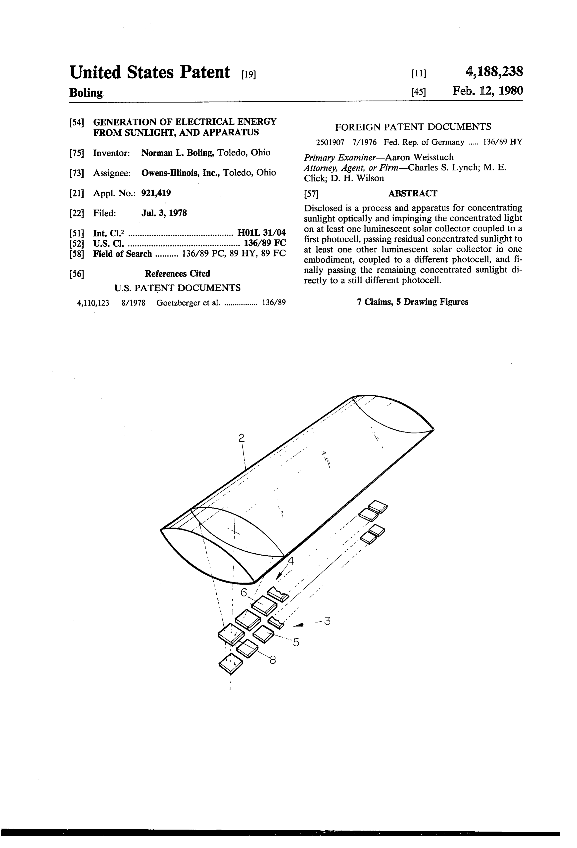
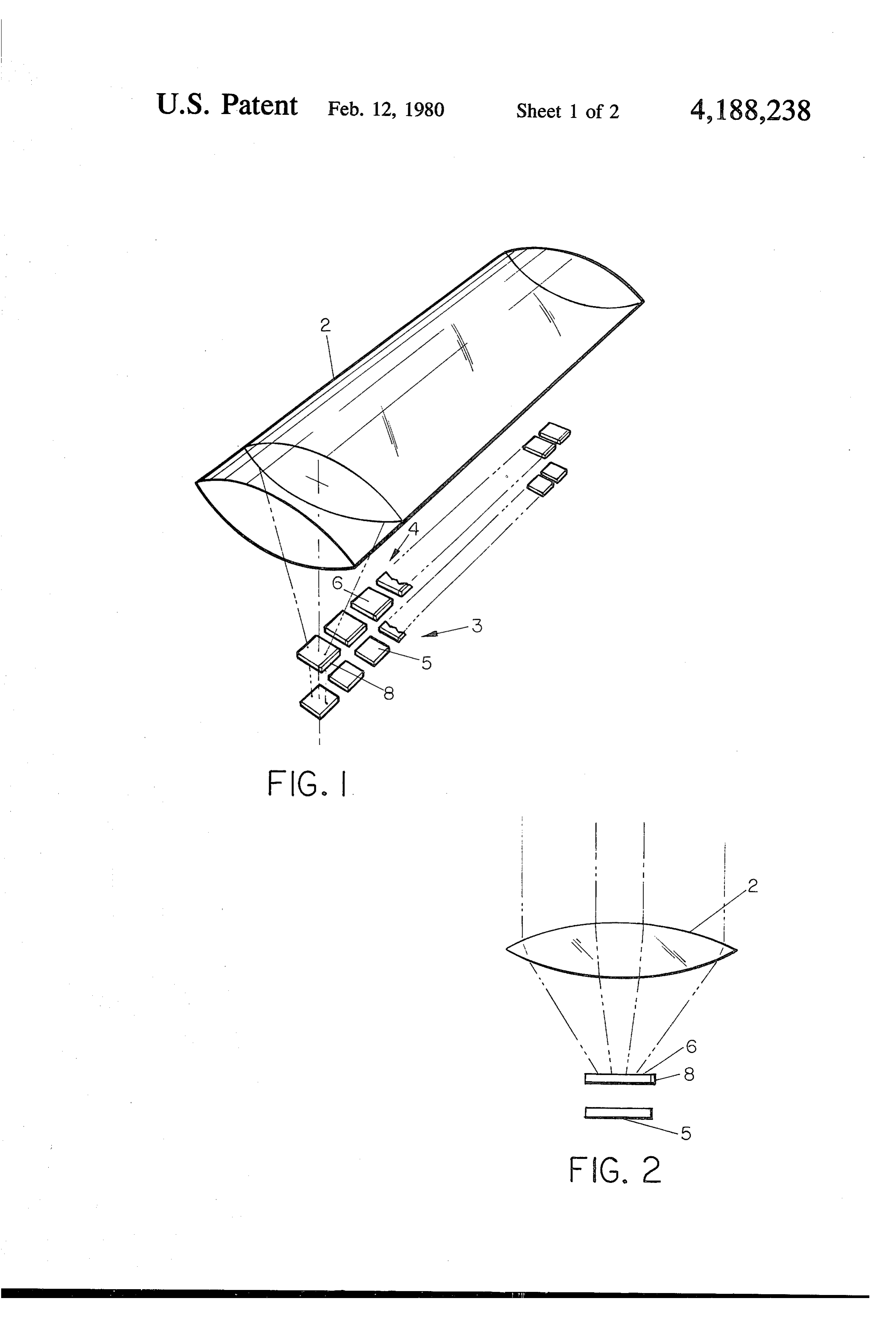
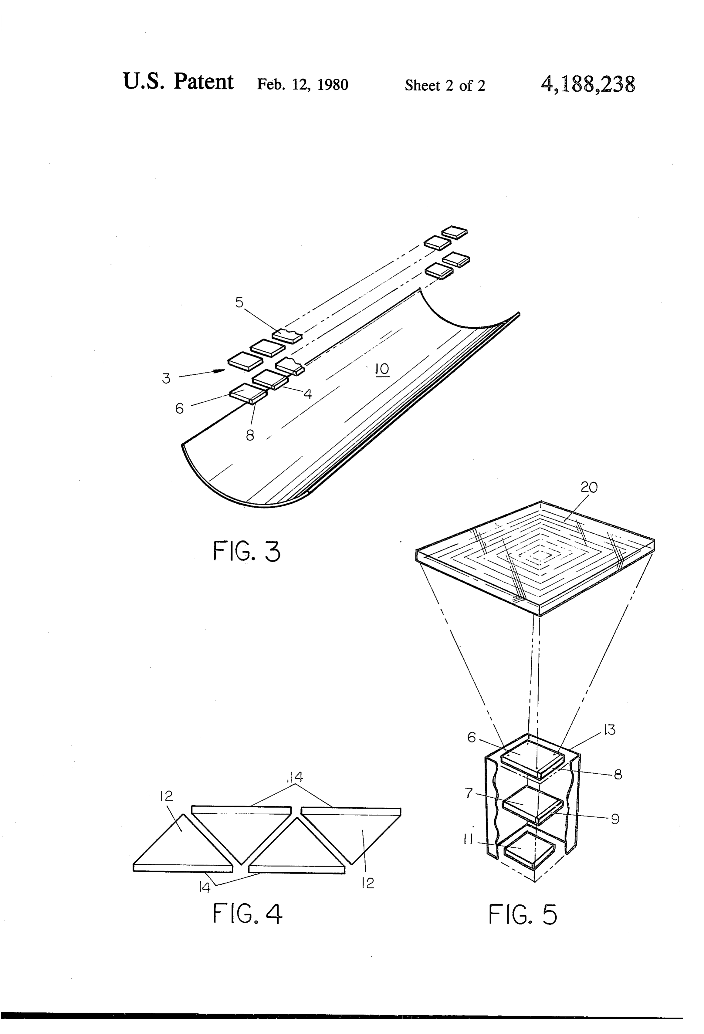
larly important with respect to choice of combination of The nature of the invention will be described relative dye and host material. This it is well-known that the to some of its embodiments, in connection with the host material can synergistically enhance or shift the drawings, of which - properties of the luminescent material, such as a dye FIG. 1 is a perspective view of an elongated lens contained therein. For instance, the separation of the overlying a row of luminescent solar collectors and a peaks of the absorption and emission spectra is influ row of photocells, enced by the properties of the solvent, such as the static FIG. 2 is an end view of FIG. 1, dielectric constant, for instance. FIG. 3 is a perspective view of an elongated, trough For the same reason, the small amounts necessary, like mirror arranged under a row of luminescent solar very expensive luminescent species can also be em 10 collectors and a row of photocells, ployed. FIG. 4 is a top view of triangular luminescent solar Also, and often of prime importance, very expensive collectors arranged in a row, and photocells can be economically employed because the FIG. 5 is a perspective view of superimposed square combination of optical concentration of the broad solar 15 luminescent solar collectors and a photocell arranged in spectrum, plus conversion of a part of the solar radia series and associated with a square Fresnel lens. tion to luminescent radiation by the luminescent solar In FIG. 1, elongated cylindrical lens 2 overlies a row collector, concentrating the emitted radiation by the 4 of square luminescent solar collectors 6, each of which is optically coupled to a semiconductor photo process of total internal reflection and coupling such voltaic radiation to a photocell, allows the use of only a rela 20 cell 8 having a P-N junction along one edge. Each solar collector 6 has its other edges coated with a tively very small amount of an expensive but efficient highly photocell material per watt of electricity generated. reflective coating or is also coupled to a photo Furthermore, practice of the present invention makes ductors cell.
voltaic Each cell 8 is connected to electrical con it more economical to effect spectral division of solar to recover theshown) (not on either side of the P-N junction generated electricity. The row 4 of col radiation by passing in series different portions of the 25 lectors 6 is directly over row solar spectrum to different luminescent solar collectors different than photocells 8 and3havingof photovoltaic cells 5, a different band each of which is optically coupled to a photovoltaic cell gap. Each ideally has about the same area as collector 6 having a different bandgap, similar to the spectral divi associated therewith.
sion disclosed in the cited Goetzberger et al. paper, The apparatus of FIG. 3 is the same as FIGS. 1 and 2 particularly on pages 124-127 as discussed in connec 30 insofar as concerns the row 4 of luminescent solar col tion with FIGS. 3, 6 and 7 therein. This is because the use of a single optical means (lens or mirror) for the thereto. 6However, lectors containing photocells 8 optically coupled instead of using a lens, a curved, first, large concentration of the radiant energy makes trough-like mirror 10 is positioned beneath the row of possible the use of much smaller luminescent solar col photocells. Row 3 of photovoltaic cells 5 is the same as lectors and much smaller photovoltaic cells in each step 35 FIGS. 1-2, except that it is positioned above row 4. per watt output in each cell. Attention is invited to the in In proposal in IBM J. Res. Develop. Vol. 22, No. 2, Mar. solar FIG. 4 is shown a top view of a row of luminescent 1978, pages 112-120, by H.J. Hovel to first concentrate shaped plate and12, collectors each of which is a flat triangular sunlight (1000 suns is mentioned) and then spectrally conductor photocell 14ofsuch each which has on one side a semi dividing the light into wavelength ranges by means of 40 silicon photocell having a P-Nasjunction, a gallium arsenide or a optical filters and feeding each wavelength band to each triangle the angle opposite the edgefor instance. In containing the separate photocells. However, the optical filters are photocell optically coupled to the luminescent solar very expensive and difficult to fabricate. collector has an angle of about 90 and the other two It will be noted that all of the foregoing advantages, angles are each about 45. Such a structure is optimum except that set forth in the last paragraph above, also 45 for several reasons, as is set forth in the cited Goetz apply to the detailed statement of the process (and cor responding arrangement of apparatus) of the invention, berger et al. article; see page 128. The other two edges of the photocell usually will have a highly reflective but considering only steps (1), (2) and (3), and in fact all coating thereon, but it is possible that one or both of of the advantages apply in such instance when the op these edges also contain a photovoltaic cell. The row of tional part of step (2) (ii) is practiced; and it is particu 50 triangular luminescent solar collectors with coupled larly noted that I have also conceived the processes photocells can be substituted for the row 4 of square (and corresponding arrangement of apparatus) dis photocells in the structure of FIGS. 1-2 or the structure closed in said steps (1) through (3), ignoring step (4). Of FIG. 3.
It will be noted that in said step (4) the residual opti The invention of course is not limited to any particu cally concentrated radiation (concentrated by means of 55 lar shape of lens or mirror or even of the luminescent a lens or mirror) directly activates a photovoltaic or Solar collector, FIG. 5 illustrates this. In FIG. 5 the solar cell, so that this cell is normally of much greater luminescent solar collector 6 with coupled photocell 8 area than the other photovoltaic cells. Thus, it is often can be of the same as described with respect to one of advantageous that such photocell in step (4) be a silicon the luminescent solar collectors of FIG. 1, but it can be semiconductor photovoltaic cell since at present Sicells 60 in association with a single square lens 20 of the Fresnel are by far the cheapest practical photocells, so that it is type, which projects a substantially square pattern of economical to omit attachment or coupling of such light somewhat within the boundaries of the lumines silicon photocell to a luminescent solar collector. cent solar collector surface, so that it is not necessary to It will be seen from the foregoing, and from the fol precisely track the sun. Beneath collector 6 is lumines lowing further description, that the novel process and 65 cent solar collector 7 having a photovoltaic cell 9 differ unique arrangement of apparatus of the invention gives ent than cell 8 and having a different bandgap, and a combination of results and of advantages, synergistic beneath 7 is photovoltaic cell different than 8 or 9, in character. having a different bandgap than either cell 8 or cell 9.
Page 7
In all of the embodiments shown in the drawings, eventually, except for minor reflection losses, reach cell FIGS. 1,2,3, superimposed rows, and in FIG. 5, the 8. The unabsorbed solar radiation and the portion of the superimposed collectors 6, 7 and the cell 11, are shown luminescent radiation not trapped is impinged on rela spaced quite far apart for purposes of illustration. In tively large photocells 5 to generate further electricity. fact, however, it is preferred that these all be closely The operation of FIG. 3 is the same except that the spaced to aid in channeling luminescent radiation leav sunlight concentrated by reflector or mirror 10 im ing one to enter the next in series. Thus, if spaced far pinges on the row of collectors 6 from below instead of apart, many of the shallow angle luminescent rays es from above.
caping the face of a given luminescent solar collector In the operation of FIG. 5 lens 20 concentrates the would not strike the element, be it a luminescent solar O sun's rays to impinge in a square pattern on most of the collector or a photocell. As a further measure to obviate area of collector 6 and the trapped luminescent radia this problem, in FIG. 5, there are shown mirrors 13, one tion finds its way to cell 8 as described relative to FIG. on each side, to reflect back the shallow rays. Of course, 1. The unabsorbed solar radiation and the portion of the again, the elements 6, 7 and 11 are all close together, so luminescent radiation not trapped is impinged on lumi that the mirrors are actually much shorter than de 15 nescent solar collector 7 and the process repeats with picted. The use of such mirrors is of course also optical further electricity being generated by photocell means in the other embodiments of the invention.
In all of the embodiments of the invention, the precise luminescent radiation radiation 7. The residual solar and the portion of the shape and size of the lens or reflector is not the essence from 7 directly to photovoltaic cellin11collector not trapped
7 passes generate still of the invention, and any suitable lens or reflector for 20 further electrical energy.
optically concentrating the light onto the luminescent In a specific example of the invention according to solar collector or collectors is suitable.
In the normal operation of the invention in any of the FIG. 5 a luminescent solar collector 6 comprises a embodiments, the optical concentrating means is ar poly(methyl methacrylate) plate 3 inches on a side and ranged in a known manner to track the Sun, and the 25 Coumarin 311containing 3 mm. thick,
130 mgs. of fluorescent dye grams of polymer dispersed luminescent solar collectors can also be so arranged, or throughout, and one edge of the plate 6 is covered by a they can be left in an optimum attitude for a collector photovoltaic cadmuim telluride semiconductor cell that does not track the sun. Of course, the tracking of the sun by the optical lens or mirror can be done in a having a P-N junction. To the other three edges there is coarse manner because it is not necessary exactly to applied a highly reflective aluminum coating. The cell outline the boundaries of the luminescent solar collec has electrical connections (not shown) on opposite sides tor. When using very high concentration ratios with the across the P-N junction. The cell is optically coupled optical lens or mirror, it may be desirable to screen out and attached by a 20 weight percent poly(methyl meth most of the wavelengths below 3500 and wave acrylate) in ethylene dichloride applied as an adhesive lengths above 9000 or 10,000 or 12,000 A, depending on 35 and serving as an index film. The solvent is of course the inherent absorption for such wavelengths by the allowed to dry, or evaporate.
luminescent solar collector medium, simply in order to Coumarin 311 is 7-dimethylamino-4-methylcoumarin. minimize the heating effects that could be caused by the The plate is made by dissolving Plexiglas poly(methyl absorption of such wavelengths. Such a screening can methacrylate) and the requisite amount of the dye in be effected in a known manner. For instance, one simple 40 ethylene dichloride to obtain a 35 weight percent solu way is to construct the lens from poly(methyl methac tion of the acrylate. The mixture is cast in the shape of rylate), which itself fairly well screens out such wave the plate of the foregoing dimensions and the solvent is lengths. Another method is to interpose a filter material allowed to evaporate slowly to form the plate, after between the lens (or the reflector) and the luminescent which the solar cell is attached as noted. For collector solar collector that does absorb the offending wave 45 7 as in FIG. 5, a glass is made and cast in the form of a lengths. plate, which is ground and polished to the dimensions Furthermore, at very high overall concentration ra 3'x3'x3 mm. Three edges are aluminized and the tios, considerable heating of the photocell can be en other edge is covered with a gallium arsenide photocell, countered, and such heating is counteracted by known applied by painting a thin film of a polysiloxane solution photocell cooling means were desired. 50 on the face of the cell, applying the cell to the edge, and Further, it should be mentioned that when a reflector allowing the solvent to evaporate. The polysiloxane is employed instead of a lens, the luminescent solar solution is 50 volume percent solution in butanol of collector is also exposed to direct sunlight, although not partially cured but further curable resin prepared as concentrated. This is a difference between using a lens described in Example 1 of U.S. Pat. No. 3,395,117 (in and a reflector, but the difference is of little conse 55 corporated herein by reference).
quence quantitatively. Another difference, of course, is The glass for luminescent solar collector 7 is made of that the luminescent solar collectors intercept a portion pure raw materials (sodium carbonate; silicic acid, sin of the sun's rays before they can reach the reflector to tered; calcium carbonate and europium oxide, Eu2O3) be concentrated. essentially entirely free of iron oxide. The glass has the In the operation of the apparatus of FIGS. 1 and 2 60 following composition:
lens 2 concentrates the sun's rays to impinge on most of the area of the row 4 of collectors 6. The luminescent species in 6 is excited by absorption of part of the rays Oxide Mile Percent and emits luminescence of longer wavelengths than the SiO 70.8 absorbed radiation. The portion of the luminescent radi- 65 NaO 5.5 ation trapped by the process of total internal reflection CO 12.3 finds its way to coupled photocell 8; note that rays EuO .4 reaching other of the three edges are reflected and
Page 8
The europium of the luminescent solar collector has having a different bandgap than said first cell, strong excitation absorption peaks at about 3900 Ä and which different cell is optically coupled to a rela about 4650 Å as well as lesser peaks at lower and higher tively small surface area of the subsequent lumines wavelengths, and has emission peaks at about 5900 and cent solar collector, and 6130 A. 5 (4) impinging the residual optically concentrated The cell 11 is a 3-inch square silicon semiconductor radiation directly on a still different photovoltaic photovoltaic cell having a P-N junction, suitably sup cell responsive to at least a portion of said residual ported for structural integrity. radiation.
In this example the size of the square Fresnel lens 2. A process of claim 1 wherein at least one of said made of poly(methyl methacrylate) is 10 inches square, 10 luminescent solar collectors is optically coupled to a designed to impinge on a 2-inch square portion of the gallium arsenide photovoltaic cell.
luminescent solar collector, so that the overall concen 3. A process which comprises tration ratio of rays reaching the cell is about 610X. (1) concentrating solar radiation optically with lens Any suitable luminescent species can be used in the or reflector means to provide optically concen method and apparatus of the invention and fluorescent 15 trated radiation and dyes, luminescent metal chelates (both usually used in (2) spectrally dividing said optically concentrated plastic), inorganic oxides such as Eu2O3 and Sm2O3, radiation by which are usually used as components of a glass lumi (i) absorbing a portion of said concentrated radia nescent solar collector, are examples of luminescent 20 tion in a first luminescent solar collector and materials.
In addition to glass and poly(methyl methacrylate) concentrating said absorbed radiation in the luminescent solar collector host materials, there can be form of longer wavelength emitted luminescent mentioned other materials useful as either the light con radiation by the process of total internal reflec ducting layer containing a luminescent species or as the tion in said first luminescent solar collector, light conducting layer containing no luminescent spe 25 (ii) passing the residual portion of said optically cies but serving as part of the trapping medium for concentrated radiation through said first lumi emitted luminescent radiation. These include, for in nescent solar collector, and repeating steps (i) stance, cured, solid silicone resins derived from trifunc and (ii) using one or more subsequent lumines tional silanes such as those disclosed in U.S. Pat. Nos. cent solar collectors in series acting on the resid 3,395,117, 3,388,114 and 3,389,121 for example; and 30 ual optically concentrated radiation passing other solid plastics and resins such as polycarbonates, through the preceding luminescent solar collec polystyrene, ethylcellulose and nitrocellulose. Also, tor, various glasses having good light conducting properties (3) passing the concentrated emitted luminescent can be used including very expensive glasses of optical radiation in said first collector to a first photovol quality. 35 tiac cell optically coupled to a relatively small As will be evident to those skilled in the art, various surface area of said first luminescent solar collector modifications of this invention can be made or followed and passing the concentrated emitted luminescent in the light of the foregoing disclosure and discussion radiation in each said subsequent luminescent solar without departing from the spirit and scope of the dis collector to a different photovoltaic cell having a closure or from the scope of the claims. different bandgap than said first cell, which differ I claim: 40 ent cell is optically coupled to a relatively small 1. A process which comprises surface area of the subsequent luminescent solar (1) concentrating solar radiation optically with lens collector, and or reflector means to provide optically concen (4) impinging the residual optically concentrated trated radiation and 45 radiation directly on a still different photovoltaic (2) spectrally dividing said optically concentrated cell responsive to at least a portion of said residual radiation by radiation.
(i) absorbing a portion of said concentrated radia 4. A process which comprises tion in a first luminescent solar collector and (1) concentrating solar radiation optically with lens concentrating said absorbed radiation in the 50 or reflector means to provide optically concen form of longer wavelength emitted luminescent trated radiation and radiation by the process of total internal reflec (2) spectrally dividing said optically concentrated tion in said first luminescent solar collector, radiation by (ii) passing the residual portion of said optically (i) absorbing a portion of said concentrated radia concentrated radiation through said first lumi 55 tion in a luminescent solar collector and concen nescent solar collector and, optionally, repeating trating said absorbed radiation in the form of steps (i) and (ii) using one or more subsequent longer wavelength emitted luminescent radia luminescent solar collectors in series acting on tion by the process of total internal reflection in the residual optically concentrated radiation said luminescent solar collector, passing through the preceding luminescent solar 60 (ii) passing the residual portion of said optically collector, concentrated radiation through said luminescent (3) passing the concentrated emitted luminescent solar collector radiation in said first collector to a first photovol (3) passing the concentrated emitted luminescent taic cell optically coupled to a relatively small radiation in said collector to a photovoltaic cell surface area of said first luminescent solar collector optically coupled to a relatively small surface area and passing the concentrated emitted luminescent of said luminescent solar collector, and radiation in each said subsequent luminescent solar (4) impinging the residual optically concentrated collector, if any, to a different photovoltaic cell radiation directly on a different photovoltaic cell
Page 9
responsive to at least a portion of said residual light, and optionally interposed between said first solar radiation. collector and said different photocell means one or 5. A process of claim 4 wherein said luminescent solar more luminescent solar collectors, each optically cou collector is optically coupled to a gallium arsenide pho pled to a different photocell means. tovoltaic cell. 5 7. An arrangement of apparatus for converting solar 6. An arrangement of apparatus for converting solar energy to electrical energy which comprises a lens or energy to electrical energy which comprises a lens or mirror to receive the collect sunlight, arranged to im mirror to receive and collect sunlight, arranged to im pinge the optically concentrated sunlight on a face sur pinge the optically concentrated sunlight on a face sur face of a luminescent solar collector optically coupled face of a first luminescent solar collector optically cou 10 to a photocell means for generating electrical energy, pled to a photocell means for generating electrical en and in series with said luminescent solar collector a ergy, and in series with the aforesaid luminescent solar different photocell means having a different bandgap collector a different photocell means having a different than the first mentioned photocell means, arranged to bandgap than the first mentioned photocell means, ar receive residual optically at- k concentrated
sunlight.
ranged to receive residual optically concentrated sun 15 s
Provenance
- Collection
- Cited prior art
- Original PDF
- patentimages.storage.googleapis.com →
- Filed
- 1978-07-03
- Pages
- 9
- Method
- pdftotext (the PDF's own text layer) + pdftoppm 300dpi page scans
- Source
- Google Patents bibliographic record
- Granted
- 1980-02-12
- Inventors
- Norman L. Boling; Owens Illinois Inc
- Transcribed from
- patentimages.storage.googleapis.com →