patent · US4161931
Vapor temperature controlled exhaust gas heat exchanger
24 July 1979
Page 1 — bibliographic record
United States Patent 19 11 4,161,931 Giardini et al. 45 Jul. 24, 1979 (54) WAPORTEMPERATURE CONTROLLED fuel is disclosed. The exhaust gas heat exchanger in EXHAUST GAS HEAT EXCHANGER cludes exhaust gas flow control valve means, responsive 75 Inventors: Dante S. Giardini, Dearborn Heights; to a vapor temperature, to control the delivery of Douglas R. Hamburg, Birmingham, heated exhaust gases to a heat exchanger coil. A heat both of Mich. exchanger housing is communicated with the exhaust 73) Assignee: Ford Motor Company, Dearborn, gas conduit of an otherwise conventional internal com Mich. bustion engine and is provided with means defining a pair of generally parallel exhaust gas flow chambers. A (21) Appl. No.: 884,331 fluid conducting heat exchanger assembly, in the form 22) Filed: Mar. 7, 1978 of one or more helical coils of fluid conducting tubing, is disposed within one of said at least two chambers in
Related U.S. Application Data the housing. The tubing communicates on an upstream end with a source of liquid fuel and communicates on a 62) Division of Ser. No. 699,004, Jun. 21, 1976, Pat. No. downstream end with a vapor reservoir. The heat ex 4,099,499. changer coil is arranged to have a maximum surface to (51) Int. C.’............................................. FO2M 31/OO volume ratio by including a plurality of individual fluid (52) U.S. C. ................................ 123/122 E; 123/133; conduits arranged in side by side relationship. 123/122 H A diverter valve member is disposed within the housing (58) Field of Search ............... 123/122 E, 122 H, 133; body and is operative to modulate the portion of the 261/144, 145 total exhaust gas stream which passes through and over 56 References Cited the heat exchanger coil assembly. A vacuum motor
1,889,270 11/1932 Thomas ........................... 23/122 H vacuum motor communicates through a vacuum valve with a source of vacuum as the internal combustion 2,473,808 6/1949 Mallory.............................. 123/122 H engine. The position of the vacuum valve, and hence 3,738,334 6/1973 ... 123/122 E.
3,783,841 1/1974 Herschler ......................... 123/122 E. the position of the diverter valve member, may be con 3,986,486 10/1976 Rabbiosi.......................... 123/122 H trolled by a temperature responsive unit which senses a Primary Examiner-Ronald H. Lazarus vapor temperature at any desired vapor temperature location.
Attorney, Agent, or Firm-Peter Abolins; Clifford L.
Sadler
An exhaust gas heat exchanger for vaporizing a liquid 3 Claims, 5 Drawing Figures
2 Awgze
Page 2
Drawing sheet — no readable text.
Page 3
Drawing sheet — no readable text.
Page 4
Drawing sheet — no readable text.
Page 5
art has also taught that a quantity of liquid fuel may be
VAPORTEMPERATURE conTROLLED added to a quantity of moving air upstream from, and EXHAUST GAS HEAT EXCHANGER for ultimate delivery to, a plurality of combustion chambers through a plurality of intake manifold con
This is a division of application Ser. No. 699,004, filed 5 duits. The advent of federally mandated internal com June 21, 1976 now U.S. Pat. No. 4,099.499. bustion engine exhaust emission standards has resulted in the investigation of techniques to substantially reduce
CROSS REFERENCE TO RELATED the quantity of pollutants produced by an internal com
APPLICATION
bustion engine. One technique proposed to reduce the
This application is related to copending commonly 10 quantity of atmospheric pollutants generated by an assigned patent application Ser. No. 660,281 filed on internal combustion engine has been to prevaporize the February 23, 1976 in the names of J. E. Auiler et al. and liquid fuel prior to delivery to the air stream. The basis titled "Vaporized Liquid Fuel Delivery and Metering of this proposal is the improved ability to control, from Systems'. cylinder-to-cylinder within any one internal combus 15 tion engine, the air/fuel ratio of the combustion mix
BACKGROUND OF THE INVENTION ture. Experimental results have indicated that to the 1. Field of the Invention extent to which the air/fuel ratio may be controlled The present invention is directed to the field of inter more accurately, the ability to implement techniques for nal combustion engine fuel delivery and metering sys the reduction of atmospheric pollutants generated by tems. In particular, the present invention is directed to 20 the internal combustion engine may also be increased. that portion of the above-noted field which is con The prior art contains a substantial number of sugges cerned with the delivery and metering of a liquid fuel to tions directed to the vaporization of a liquid fuel for use provide a combustible air/fuel mixture for an internal in a fuel delivery system for an internal combustion combustion engine. More particularly still, the present engine. These prior art solutions have generally cen invention is directed to that portion of the above-noted 25 tered around using the exhaust gases of the internal field which is concerned with the delivery and metering combustion engine as a source of heat for heating a of a liquid fuel which has been vaporized prior to mix liquid fuel stream. However, the prior art suggestions ture with an air stream. More particularly still, the pres have not been wholly technically feasible in terms of ent invention is directed to that portion of the above providing a vaporized liquid fuel to an internal combus noted field which is concerned with the vaporization of 30 tion engine in an automotive environment. In particular, a liquid fuel in quantities sufficient to maintain the oper the automotive environment requires that fuel be deliv ation of an internal combustion engine in an automotive ered to the internal combustion engine with mass flow vehicle environment. More particularly still, the present rates which may vary by a factor of twenty to one invention is directed to that portion of the above-noted (20:1). Any liquid fuel vaporizing system must therefore field which is concerned with the provision of an inter 35 be capable of accommodating vaporization of liquid nal combustion engine waste heat operated liquid fuel fuel which may be consumed by the engine with mass vaporizer operative to provide quantities of vaporized flow rates which vary by twenty to one (20:1). liquid fuel sufficient to maintain operation of the inter A further problem which has not been adequately nal combustion engine. More particularly still, the pres addressed by the prior art involves the recognition that ent invention is directed to that portion of the above commercially available gasolines can be expected to be noted field which is concerned with the provision of an completely vaporized attemperatures above about 425' internal combustion engine exhaust gas system situated F. The temperature of the exhaust gases produced by an heat exchanger communicating with a source of liquid internal combustion engine can readily be substantially fuel and operative, under normal engine operating con in excess of this value. It is therefore a specific object of ditions, to transfer sufficient quantities of heat from the 45 the present invention to provide a liquid fuel vaporiza exhaust gas to the liquid fuel within the heat exchanger tion apparatus for insertion within the exhaust gas sys to provide sufficient quantities of vaporized liquid fuel tem of an internal combustion engine which apparatus to sustain engine operation. More particularly still, the includes means to vary the temperature of the vaporiza present invention is directed to that portion of the tion apparatus. It is also an object of the present inven above-noted field which is concerned with the provi 50 tion to provide liquid fuel vaporization apparatus which sion of means for modulating the temperature of an is adapted to accommodate vaporization of a liquid fuel exhaust gas actuated liquid fuel vaporizer. More partic having a mass flow rate which may vary by a factor of ularly still, the present invention is directed to that twenty to one (20:1). In accommodating an engine portion of the above-noted field which is concerned which may consume masses of fuel which may vary by with the provision of a liquid fuel vaporizer positionable 55 a substantial margin, the cross referenced copending within the exhaust gas conduit of an internal combus commonly assigned patent application teaches the use tion engine having means responsive to the temperature of a variable volume vapor reservoir. It is therefore a of a vaporized liquid fuel to modulate the quantity of further and specific object of the present invention to exhaust gas being supplied to the liquid fuel vaporizer. provide a liquid fuel vaporization apparatus for charg 2. Description of the Prior Art 60 ing a vapor reservoir.
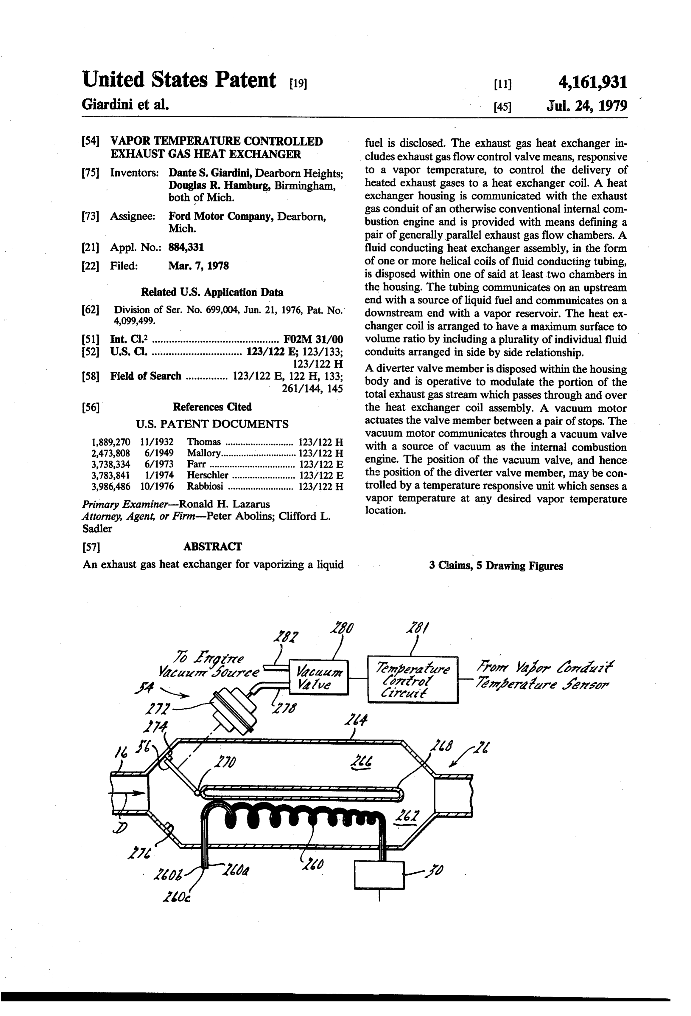
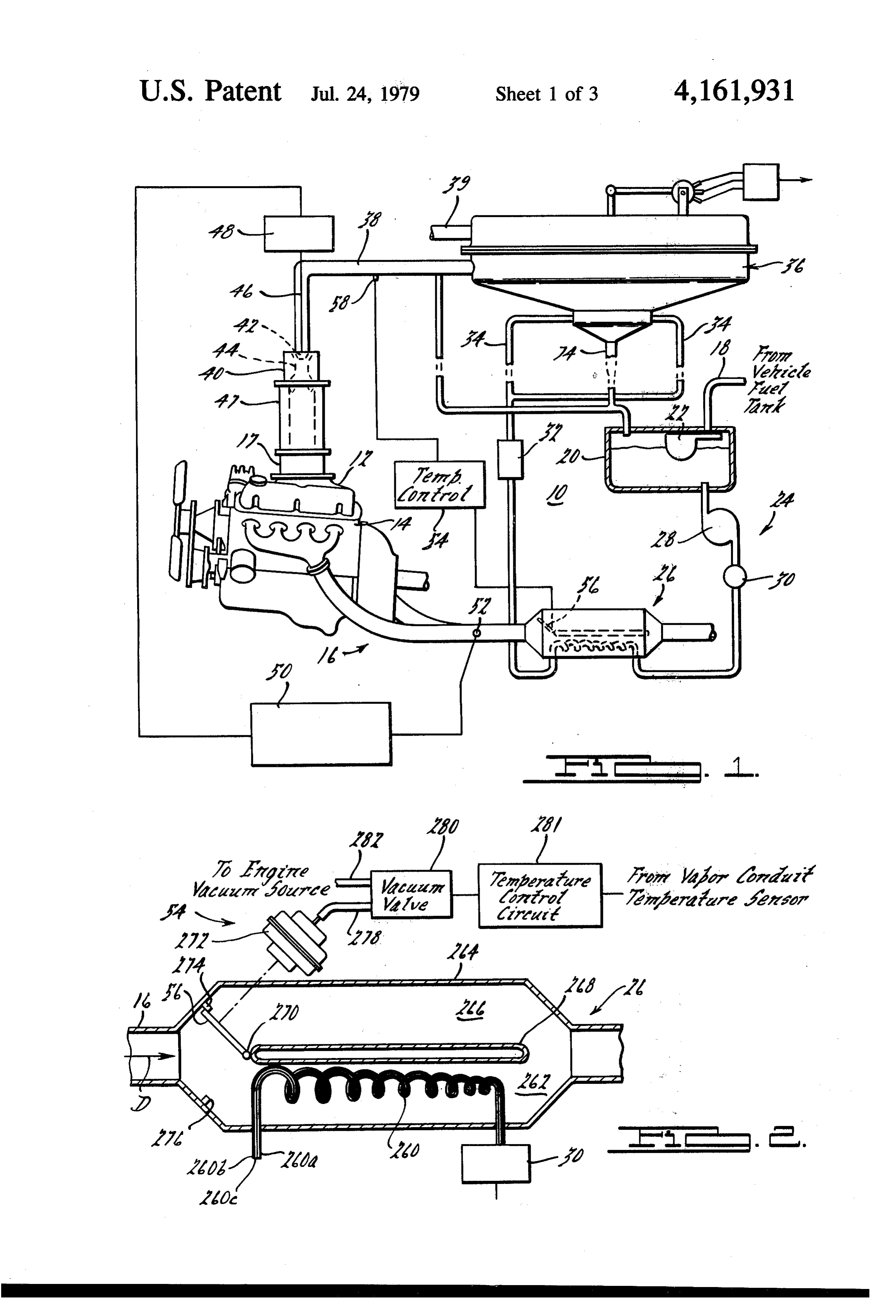
It is well known in the prior art to provide a fuel in BRIEF DESCRIPTION OF THE DRAWING liquid form to a moving air stream for delivery to the combustion chambers of an internal combustion engine. FIG. 1 illustrates a vaporized liquid fuel delivery and The prior art systems generally have utilized mechani metering system with which the present invention is of cal or electromechanical fuel delivery and metering 65 utility.
apparatus to provide metered quantities of liquid fuel in FIG. 2 illustrates the liquid fuel vaporizer according proximity to, and in some cases into, the combustion to the present invention in a partly schematic, partly chambers of an internal combustion engine. The prior sectional view.
Page 6
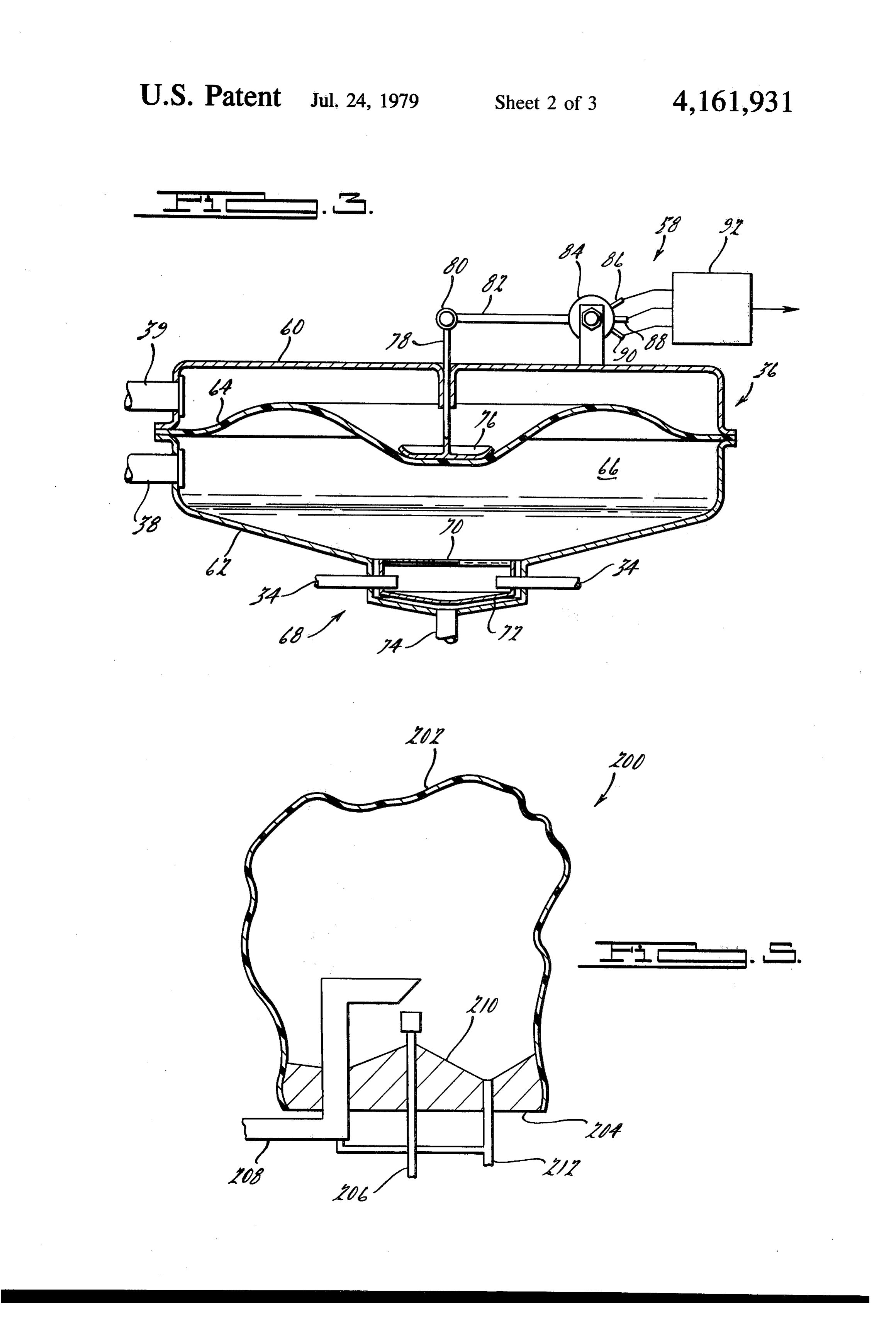
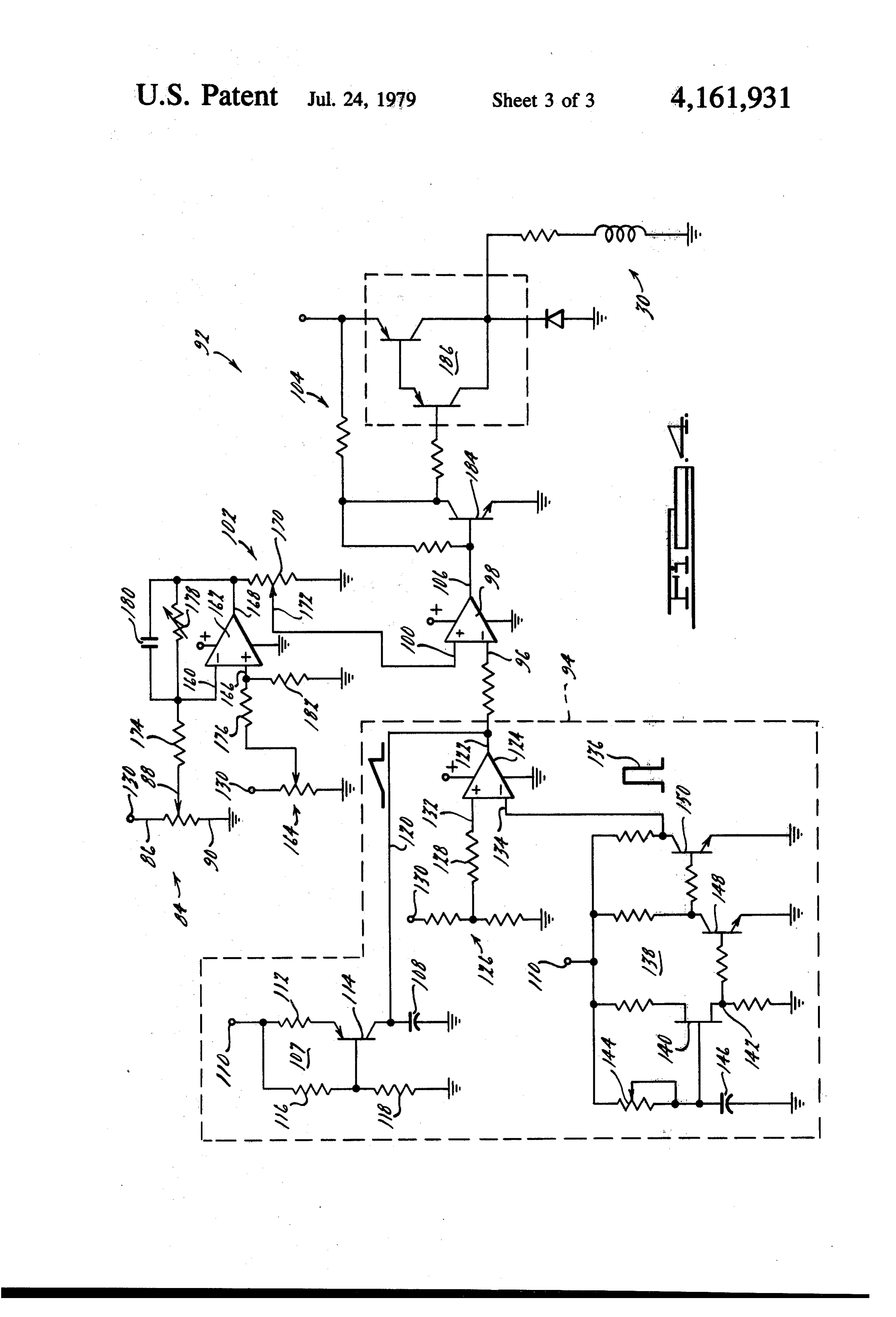
FIG. 3 illustrates the vapor reservoir and vapor vol with the vapor reservoir 36 when the auxiliary heating ume control means according to the FIG. 1 embodi means 32 are not required as a vapor supply source. ment in an enlarged, partly sectional, partly diagram Vapor reservoir 36 is communicated by way of con matic view. duit 38 with carburetor means 40. As used herein "car FIG. 4 illustrates the electrical control circuit for buretor' means any device for mixing fuel with air to maintaining a desired vapor volume in the vapor reser establish a combustible air/fuel mixture. As illustrated voir. in FIG. 1, the vapor delivery nozzle 42 of vapor deliv FIG. 5 illustrates an alternative embodiment for the ery conduit 38 is positioned within the low pressure vapor reservoir according to FIG. 3. Zone formed by the metering venturi means 44 of the 10 carburetor means 40. A movable pintle 46 is situated
DETALED DESCRIPTION OF THE within the vapor delivery nozzle 42 and is controlled by PREFERRED EMBODIMENT servomechanism means 48. Carburetor means 40 in Referring now to the drawing wherein like numerals cludes mixing section 47 which intercommunicates the designate like structure throughout the various views metering venturi means 44 with the throttle body 17 and thereof, FIG. 1 illustrates a vaporized liquid fuel deliv 15 the intake manifold 12.
ery and metering system 10. The vaporized liquid fuel Servomechanism 48 may be for example a conven delivery and metering system 10 is arranged to provide tional servometer operated electrically or by electrome a combustible air/fuel mixture to the intake manifold 12 chanical means. Servomechanism 48 receives an input of an internal combustion engine 14. Internal combus command signal from servomechanism control means tion engine 14 is provided with combustion by-product 20 50. As here illustrated, servomechanism control means exhaust gas system or conduit means 16. Intake mani 50 are arranged to be responsive to an exhaust gas sen fold 12 is provided with throttle body 17. As illustrated, sor 52 which may for example, a titania exhaust gas internal combustion engine 14, intake manifold 12, to FIG.according
throttle body 17 and exhaust conduit means 16 are sub 25 provided1,withfuel delivery and metering system 10 is also temperature control means 54. Tempera stantially conventional. For purposes of illustration, it ture control means 54 are arranged to be responsive to will be considered that internal combustion engine 14 is the vapor temperature in vapor delivery conduit 38 in of the type adapted for installation and use in powering order to control an exhaust gas flow diverter valve 56 an automotive vehicle, not shown. which is described in greater detail hereinbelow with System 10 is arranged to receive liquid fuel from a 30 reference to FIG. 2.
conventional liquid fuel reservoir or tank, not shown, Referring now to FIG. 2, the primary liquid fuel through conduit 18. Conduit 18 communicates with heater means 26 according to the present invention is intermediate liquid fuel reservoir 20. The communica illustrated in a partly schematic, partly sectional, partly tion between conduit 18 and intermediate reservoir 20 may be controlled, for example, by a pivoted float valve 35 a helical coil view.
diagrammatic Primary heater means 26 comprise 22 in the conventional manner. As will be appreciated, within heating chamberfuel
conduit which is disposed of a bi-chambered housing liquid fuel could be pumped through conduit 18 by 264. Housing 264 is here shown conventional pumping means such as the conventional tion of exhaust gas conduit 16. toIn be formed as a por order to achieve a mechanical or electrical fuel pump normally used in high surface-to-volume ratio for heat exchanger coil or automotive vehicles. helix 260, consonant with rapid liquid vaporization of Liquid fuel contained in intermediate reservoir 20 liquid fuel within coil 260, a plurality of fuel conduits may be provided by coarse liquid fuel delivery means 24 260a, to the primary heating means 26 according to the pres cating260b and 260c are shown as being utilized in fabri heat exchanger coil or helix 260. Each fuel con ent invention. Coarse liquid fuel delivery means 24 may duit 260a, 260b, 260c is preferably fabricated out of a include, for example, an electrical or mechanical liquid 45 thin walled material having good heat transfer capabil pump 28 and/or a liquid flow control valve 30. An ity and the ability to withstand the corrosive environ auxiliary means 32 is arranged in fluid serial flow rela ment of the exhaust system 16. We have found stainless tionship with respect to the primary heating means 26 steel tubing to be suitable. The coil 260 may be formed so that fuel provided from intermediate reservoir 20 on a mandrel by any of the well known techniques. The would flow serially through the primary heating means SO individual conduits 260a, 260b, and 260c are would in 26 and thence through auxiliary heating means 32. The side-by-side alignment and may be welded or otherwise auxiliary heating means 32 are shown to be communi bonded together to equalize the temperature gradients cated via conduits 34 to vapor reservoir 36. between individual coils. Housing portion 264 includes As illustrated in FIG. 1, the primary and auxiliary a generally centrally disposed baffle means 268 to define heating means 26, 32 are connected in serial fluid flow 55 an exhaust gas flow chamber 266 which is separated relationship. In order for efficient operation of the auxil from the heat exchanger chamber 262. iary heating means 32, it should be designed for rela The flow of exhaust gases, in the direction of arrow tively low fuel flow consonant with operation of the D, through heat exchanger chamber 262 within ex associated engine 14 at idle. As such, however, the changer housing 264 is here controlled by exhaust gas auxiliary heating means 32 could present a high impe flow diverter valve 56. Exhaust gas flow diverter valve dance to fluid flow and could impede engine operation 56 is pivotally connected as at 270 to the central baffle under high fuel consumption conditions. It is therefore 268 and is positioned in response to the vapor tempera contemplated that the primary and auxiliary heating ture responsive valve control means 54. Temperature means could be connected in parallel fluid flow. It is responsive valve control means 54 include a conven also contemplated to provide a fluid by-pass valve 65 tional vacuum motor means 272, vacuum valve 280 and downstream from primary heating means 26 and up temperature control circuit means 281.
stream from the auxiliary heating means 32 to place the Exhaust gas flow diverter valve 56 is mechanically primary heating means 26 in direct fluid communication linked or coupled to vacuum motor 272. Vacuum motor
Page 7
272 is operative to pivotally rotate diverter valve 56 tight vapor space or storage zone 66. Movable wall between the positions denoted by stops 274,276 on the means 64 may be formed as a diaphragm member and side wall of housing 264. Vacuum motor 272 is commu may be fabricated from any suitable, flexible, high tem nicated by vacuum hose 278 to vacuum valve 280. Vac perature and vapor resistant material. Movable wall uum valve 280 communicates with source of vacuum means 64 may be, for example, in the case of vaporized through vacuum conduit 282. The vacuum source may liquid gasoline, a polytetrafluoroethylene (PTFE) mate conveniently be an appropriate portion of the engine 14. rial. Other materials are known and can be used. PTFE Vacuum valve 280 may be, for example, a solenoid material has a maximum operating temperature in the operated valve to selective communicate vacuum contemplated environment of about 600 F. while com motor 272 with a vacuum source in response to electri 10 mercially available gasoline may be expected to be com cal signals applied by temperature control circuit means pletely vaporized attemperatures not exceeding 450 F. 281. Vacuum valve 280 is responsive to temperature A suitable thickness for such a diaphragm member has control circuit means 281 to command vacuum motor been found to be 2 mils. smaller thicknesses are also 272 to actuate exhaust valve 56. By actuating exhaust suitable, provided that manufacturing induced defects flow control valve 56 to a position in substantial abut 15 as perforations are avoided.
ment with stop 276, the flow of exhaust gas will be Lower canister housing section 62 is provided with a diverted from passage through chamber 262 which downwardly extending vapor inlet and condensate col includes heat exchanger coil 260 to passage through lection section 68. Vapor delivery conduits 34 are ar chamber 266. Temperature control circuit means 281 ranged to direct a vapor stream into the interior of may be arranged to be responsive to a thermistor 58. 20 section 68 where the vapor may communicate through Thermistor 58 may be located, for example, within swirl fins 70 with the vapor storage zone 66. A shield vapor conduit 38. Alternatively, thermistor 58 could be member 72 is received within section 68 and is attached in thermal exchange contact with the vapor within to and supported by vapor inlet tubes 34. Condensate vapor reservoir 36 or with any other convenient struc collection section 68 is provided with a generally down tural member having a temperature which is indicative 25 wardly extending generally conical and plate member of the temperature of the vapor within the vapor deliv having condensate collection conduit 74 affixed thereto ery portion of the fuel delivery and metering system 10. at its lowest point. Shield member 72 is arranged to be By way of example, temperature responsive circuit spaced away from the walls of condensate collection means 281 may include an electrical bridge circuit section 68 and to be thermally floating with respect to which includes, as a portion thereof, the thermistor 58 30 the lower housing member 62 and the condensate col and an electronic comparator circuit to establish the lection section 68. Shield member 72 is arranged to minimum desired vapor temperature. Such circuits are provide a barrier between the relatively high tempera well known in the art. As thus described, vacuum motor ture inlet vapor and the lower temperature condensate 272 and exhaust diverter valve 56 may be cooperative to collection section 68 and any condensed fuel which may cause substantially all of the exhaust gas flow to pass 35 be accumulated therein. Preferably, shield member 72 is through the chamber 262 and hence over heat ex fabricated out of a low thermal inertia material such as changer coil 260 or to pass through by-pass chamber a thin stainless steel or suitable ceramic. Swirl fins 70 266. With the diverter valve 56 in an intermediate posi promote intermixing of the higher temperature inlet tion, a portion of the exhaust flow may pass through vapor with any vapor residual within vapor zone 66 to each chamber. Since placement of the diverter valve 56 encourage relatively uniform temperature distribution in the extreme positions could ordinarily be expected to within zone 66. In operation, any vaporized fuel which result in substantial temperature variation of the vapor would condense due to contact with a low temperature being provided to vapor reservoir 36, the thermal iner surface within the vapor reservoir 36, and particularly tia of the heat exchanger coil 260, the central baffle 268 the less volatile fractions of gasoline, would be col and the thermal coupling between the two chambers of 45 lected within section 68 and would flow through con the housing may be selected to give adequate tempera densate return conduit 74 for return to the intermediate ture smoothing commensurate with acceptable heat tank. 20.
exchanger warm-up and good transient response times. The central portion of movable wall means 64 is We have found that good results can be obtained with connected to plate member 76. Plate member 76 is con a primary heater means 26 according to the present 50 nected to movable position sensing rod 78. Position invention having a fuel volume within the vaporizer sensing rod 78 is pivotally connected at pivot 80 to lever section, coil 260, of about one percent (1%) of the dis arm 82 of rheostat member 84, Rheostat member or placement of the associated engine. We have also found potentiometer 84 is provided with three electrical ter that sufficient heat will be present within chamber 262 minals 86,88 and 90 which communicate with the vapor after about twenty (20) seconds of engine operation (at 55 volume control means 92.
an ambient temperature of about 70F) to fully vapor Vapor region 66 communicates with the engine 14 ize liquid fuel flowing through fuel conduits 260a, 260b, through vapor conduit 38. Reference conduit 39 com 260c. It will be appreciated that heat-up time will be, at municates the upper housing section 60 and particularly least in part, a function of the proximity of the primary the nonvapor surface of movable wall means 64 with heating means 26 to the engine 14 and the ambient tem the source of air being utilized by internal combustion perature. engine 14. In those instances where the air being in Referring now to FIG. 3, the vapor reservoir 36 and gested by engine 14 passes through an air cleaner, con its associated vapor pressure control means 58 are illus duit 39 would preferably communicate with the interior trated. Vapor reservoir 36 is comprised of a canister or 65 of the air cleaner. In those instances where atmospheric housing having upper and lower housing sections 60, air is provided directly to internal combustion engine 62, respectively. A movable wall member 64 is sealingly 14, reference conduit 39 would communicate directly to confined between extending flanges of the upper and the atmosphere. Reference conduit 39 thus provides the lower canister housing sections 60, 62 to define a vapor nonvapor side of movable wall portion 64 with a pres
Page 8
sure reference which is substantially identically equal to Input terminal 134 of transistorized gate circuit 124 the pressure of the air being provided to, and immedi receives a periodically repeated voltage pulse signal, ately upstream from, carburetor means 40. Such as at 136, which is generated by oscillator circuit Referring now to FIG. 4, the vapor volume control 138. Oscillator circuit 138 is electrically energized from means 92 of FIG. 3 is illustrated as an electronic circuit. a voltage terminal 110. Oscillator circuit 138 is opera Vapor volume control means 92 is adapted to control tive to generate a voltage pulse which goes from sub valve 30 of coarse pumping and valving means 24 in stantially the ground level to substantially the value of response to the quantity of vapor within vapor region the source voltage and has a very narrow pulse width. 66 as indicated by potentiometer 84. In the presently The occurrence at input terminal 134 of a pulse having preferred embodiment of the vaporized liquid fuel sys 10 a voltage value which is in excess of the voltage value tem according to the present invention, coarse fuel of the generally constantly applied voltage appearing at metering valve 30 is a commercially available electri terminal 132 will be operative to cause the output of cally controlled injection valve used, for example, in transistorized gate circuit 124 to approach ground electronic fuel injection systems. Such valves are de value. This will impose a substantially ground voltage signed and intended to deliver a metered quantity of 15 on conductor 120 to thereby discharge capacitor 108. liquid fuel to the intake manifold of an internal combus Removal of the pulse from input terminal 134 will allow tion engine in proximity to an intake valve. It will be capacitor 108 to recharge. Thus, a saw tooth voltage appreciated that a coarse fuel metering pump 28 could signal going from a near ground or zero value to a be similarly controlled. Vapor volume control circuit maximum or full value voltage will be applied to termi nal 96 of comparator 98. The pulse width of the output 92 includes a first circuit portion, contained within 20 signal dashed line 94, for generating a saw tooth wave form generated at output terminal 106 by comparator for application to one input terminal 96 of a comparator 98 will then be a function of the voltage appearing on 98. The other input terminal 100 of comparator 98 is input terminal 100.
The oscillator circuit 138 includes unijunction transis arranged to receive a variable voltage signal from con trol circuitry 102. This variable level voltage signal is 25 tor 140 and associated circuitry operative to generate a generated in response to potentiometer 84. Valve con cuitrytrain pulse at circuit junction 142. The associated cir includes variable resistance 144 and capacitor 146 trol circuitry 104 is responsive to the output signal from arranged in an RC network and operative to periodi comparator 98 appearing at output terminal 106 to se cally charge and discharge the capacitor 146 to cause lectively energize the coarse fuel metering valve 30. 30 breakdown of the unijunction transistor 140. The pulses Saw tooth generator 94 includes a ramp generator portion 107 which is operative to generate a linearly appearing at circuit junction 142 may be shaped by additional circuitry associated with transistors 148, 150 increasing voltage across capacitor 108. Capacitor 108 to is charged by current flow from the terminal 110 allyestablish uniform the pulse train of pulses 136 having a gener pulse width with rapid rise and fall. Resis through resistor 112 and transistor 114. Transistor 114 is 35 tance 144 is here held in an "on' or conductive condition by the voltage the frequency ofshown the to be variable in order to vary resulting pulse train. We have divider comprised of a pair of resistances 116, 118, found that a pulse frequency of 50Hz and a pulse width which may be, for example, of the same resistance of 0.1 usec. gives good results.
value. Resistances 116, 118 are operative to apply a reduced voltage such is approximately one-half of the 90The potentiometer 84 is connected by its terminals 86, input voltage to the base terminal of transistor 114. ground. Thea slider between voltage terminal, such as terminal 130, and 88 of potentiometer 84 is coupled to
Transistor 114 will be conductive and will charge ca the movable wall member 64 of vapor reservoir 36 as pacitor 108 whenever the voltage on the base terminal described hereinabove with reference to FIG. 3. The exceeds the voltage on the collector terminal and is less voltage developed by potentiometer 84 at slider 88 is than the voltage on the emitter terminal. The rate of 45 therefore a function of the position of the movable wall change of capacitor 108 can be controlled by the magni member 64 and hence of the quantity of vapor within tude of resistance 112. the vapor region 66. This voltage is applied to one input Capacitor 108 intercommunicates the collector of terminal 160 of comparator 162 to be compared with a transistor 114 to ground. The other or nonground side reference voltage applied at input terminal 166. The of capacitor 108 is communicated by conductor 120 to SO reference voltage is developed by potentiometer 164. output terminal 122 of transistorized gate circuit 124. Comparator 162 is arranged to provide an output signal One input terminal of transistorized gate circuit 124 is at output terminal 168 which signal represents the dif provided with a constant voltage signal derived from a ference between the applied input signals. The output conventional voltage divider 126 through resistance signal appearing at output terminal 168 is applied 128. Voltage divider 126 is connected electrically be 55 through potentiometer 170 to the input terminal 100 of tween terminal 130 and the ground and is operative to comparator 98.
provide a constant voltage signal at input terminal 132. The input terminals 160, 166 of comparator 162 are For purposes of this circuit description, voltage termi provided with input resistances 174, 176 respectively. In nal 110 may be considered to represent a first level of addition, variable feedback resistance 178 and capacitor voltage and voltage terminal 130 may be considered to 60 180 are arranged electrically in parallel interconnecting represent a second level of voltage with all similarly input terminal 160 with output terminal 168. The ratio designated terminals being in electrical communication of the resistance of feedback resistance 178 compared with the same voltage source. Transistor 114 is ar with the resistance of input resistance 174 will establish ranged to act as a constant current source in charging the gain of the comparator and the gain so established capacitor 108. The voltage across capacitor 108 will 65 can be expected to be stable in extended use. Capacitor increase substantially linearly until a value is reached 180 is selected to prevent relatively high frequency which would reverse bias the base-collector junction of variations in the voltage appearing at output terminal transistor 108 causing the transistor to switch off. 168. This is desirable to prevent a relatively high fre
Page 9
quency instability in the closed loop which includes the will cause the power amplifier 186 to be “on” to ener "mechanical' elements of the primary heater means 26 gize coarse fuel metering valve 30. With valve 30 on or and the vapor reservoir 36. For good d.c. stability, the open, additional quantities of fuel will be allowed to values of resistance of the input resistances 174, 176 are flow to the primary heater means 26 for vaporization selected to be substantially equal. The value of the thereby. For very low volumes of vapor in vapor reser grounding resistance 182 is also selected to be approxi voir 36, the threshold signal will be high and the pulse mately equal to the value of the feedback resistance 178 width will increase thereby increasing the "on' time of for good d.c. stability. power amplifier 186 and the open time of coarse fuel With potentiometer 84 disconnected, potentiometer metering valve 30.
164 is adjusted to make the voltage at output terminal 10 168 sufficiently high to just provide maximum fuel de voirReferring 200 is now to FIG. 5, an alternative vapor reser shown. Vapor reservoir 200 includes a col livery to the primary heater means 26. Potentiometer 84 lapsible envelope comprised of the thin membrane of is then connected and adjusted so that the voltage at plastic material 202 which is sealingly attached to base output terminal 168 is as previously set. Feedback resis plate member 204. Base plate member 204 tance 178 is then adjusted to give a zero output voltage 15 vided with an inlet source 206 of vaporizedmay be pro at output terminal 168, corresponding to the vapor and a vapor conduit 208 communicating the interiorfuel liquid
reservoir being filled, by holding the vapor reservoir the reservoir 200 with the internal combustion engine, movable wall portion in an up or "filled' condition. As not shown. Vapor conduit 208 is shown as having its illustrated in FIG. 3, a depleted vapor supply in reser inlet orifice arranged in the central portion of envelope voir 36 will cause the voltage appearing at input termi 20 nal 160 to decrease. The voltage appearing at output 202. wardly
The inlet orifice of inlet 206 is preferably down directed to promote thermal mixing. Base plate terminal 168 is arranged to increase as the voltage at 204 is provided with a condensate collection depression input terminal 160 decreases from the reference level 210 which communicates with condensate return con established by potentiometer 164.
Potentiometer 170 is connected between output ter 25 conduit 208, the condensatecondensate duits 212. In order to drain return from the vapor conduit 212 also minal 168 and ground. The slider 172 of potentiometer 170 is connected to the input terminal 100 of compara communicatesWe claim:
with vapor conduit 208.
tor 98. The slider 172 may also be connected to the apparatus controlling the position of the throttle valve 1. An exhaust gas heat exchanger for inclusion in the within throttle valve body 17. For example, a closed 30 exhaust gas conduit system of an automotive internal throttle condition would cause the slider to reduce the combustion engine, comprising in combination: level of the voltage signal applied to input terminal 100. housing means having an exhaust gas inlet port and an This arrangement will operate to vary the effective gain exhaust gas outlet port; of comparator 162 in response to actual operation of baffle means received within said housing means op internal combustion engine 14 to assist in filling the 35 erative to partition the interior of said housing vapor reservoir when the throttle valve of the engine is means into at least two chambers, said chambers opened and to assist in preventing excess vapor forma being arranged for parallel exhaust flow communi tion when the throttle valve is moved toward a closed cation between said inlet port and said outlet port; position. Potentiometer 170 will also assist in preventing heat exchanger coil means received within one of said relatively low frequency instability in the loop which chambers and arranged for conveyance of a fluid; includes primary heater means 26 and vapor reservoir diverter valve means within said housing in proximity 36. to said inlet port and operable to direct exhaust gas Comparator 98 is arranged to generate an output passing through said inlet port to flow to said outlet voltage signal at output terminal 106 whenever the port substantially through a selected one of said voltage appearing on input terminal 96 is below the 45 chambers;
level of voltage established at the input terminal 100. valve control means for controlling the position of Thus, with a saw tooth input signal at input terminal 96, said diverter valve means; a pulse train of rectangular pulses will be generated at said heat exchanger coil means being arranged for output terminal 106 with a frequency equal to the fre conveyance of a fluid fuel which is a liquid under quency of the saw tooth wave train and a pulse width 50 standard temperature and pressure conditions and determined by the portion of any particular saw tooth which may be vaporized by heating and said valve pulse which is below the threshold voltage. The output control means including temperature responsive signal will be applied to output transistor 184 which will means arranged to be responsive to the fluid fuel invert the signal to apply an input to the power ampli temperature at a selected fluid fuel location for fier circuitry 186 to control energization of the coarse 55 controlling the application of exhaust gas heat to fuel metering valve 30. Thus, when vapor reservoir 36 said coil means, said selected liquid fuel location is is full, the threshold signal will be substantially zero and downstream, in the fluid conveyance direction, the output signal at terminal 106 will be substantially from the heat exchanger coil means; and constant at the zero level. This will turn output transis said valve control means further include vacuum tor 184 "off" thereby applying a high voltage signal to 60 motor means communicable to a vacuum source power amplifier 186 causing power amplifier 186 to be and communicating with said temperature respon "off". This will result in closing coarse fuel metering sive means operative to provide diverter valve valve 30 and terminating fuel delivery to the primary means positioning.
heating means 26. As the vapor is depleted from vapor 2. A liquid fuel vaporizer including an exhaust gas reservoir 36, the threshold signal will rise causing the 65 heat exchanger for inclusion in the exhaust gas conduit output signal to appear as a train of pulses at the saw system of an internal combustion engine, comprising in tooth frequency. The pulse portion of the output signal combination:
pulse train will switch output transistor 184 "on' and a liquid fuel reservoir means for storing liquid fuel;
Page 10
housing means having an exhaust gas inlet port and an fuel vapor quantity sensing means for sensing the exhaust gas outlet port; quantity of fuel vapor resident in said fuel vapor baffle means received within said housing means op storage means;
erative to partition the interior of said housing a second conduit means for carrying the fuel from means into at least two chambers, said chambers said heat exchanger coil to said fuel vapor storage means;
being arranged for parallel exhaust gas flow com a heat exchanger transfer rate modulating means for munication between said inlet port and said outlet modulating the heat exchange transfer rate be port; tween the fuel flow and the exhaust gas flow in heat exchanger coil means received within one of said 10 response to sensed vapor quantity in said fuel vapor chambers and arranged for conveyance of a fluid storage means whereby the quantity of fuel vapor fuel for the internal combustion engine; within said vapor storage means may be maintained diverter valve means within said housing in proximity within a desired range; and to said inlet port and operable to direct exhaust gas said heat exchange transfer rate modulating means passing through said inlet port to flow to said outlet 15 including a flow control means for modulating the port substantially through a selected one of said rate of delivery of liquid fuel to said heat exchanger coil means.
chambers, said diverter valve means being movable 3. The liquid fuel vaporizer as recited in claim 2 between at least a first position and a second posi wherein said heat exchanger coil means is arranged for tion whereby in said first position substantially all 20 conveyance of a fluid fuel which is a liquid understan of the exhaust gas flow is in a first of said at least dard temperature and pressure conditions and which two chambers and in said second position substan may be vaporized by heating and said valve control tially all of the exhaust gas flow is in a second of means include temperature responsive means arranged said at least two chambers; to be responsive to the fluid fuel temperature at a se valve control means for controlling the position of 25 lected fluid fuel location for controlling the application said diverter valve means; of exhaust gas heat to said coil means, thereby modulat a first conduit means for carrying fuel for the internal ing the heat exchange transfer rate at said heat ex combustion engine to said heat exchanger coil changer coil means in response to the sensed tempera means; ture of a generated fuel vapor may be maintained within a fuel vapor storage means for providing a means of 30 a desired range;
containing fuel vapors for use in the internal com said selected liquid fuel location is downstream, in the bustion system, said fuel vapor storage means being fluid conveyance direction, from said heat ex in communication with said heat exchanger coil changer coil means; and said valve control means further include vacuum means; 35 motor means adapted to be communicable to a fuel temperature sensing means for sensing the tem vacuum source and communicating with said tem perature of the fuel at a location downstream in the perature responsive means operative to provide direction of fuel flow from said heat exchanger coil diverter valve means positioning. means;
Provenance
- Collection
- Cited prior art
- Original PDF
- patentimages.storage.googleapis.com →
- Filed
- 1978-03-07
- Pages
- 10
- Method
- pdftotext (the PDF's own text layer) + pdftoppm 300dpi page scans
- Source
- Google Patents bibliographic record
- Granted
- 1979-07-24
- Inventors
- Dante S. Giardini; Douglas R. Hamburg; Ford Motor Co
- Transcribed from
- patentimages.storage.googleapis.com →