patent · US4340032A
Solar heating system
20 July 1982
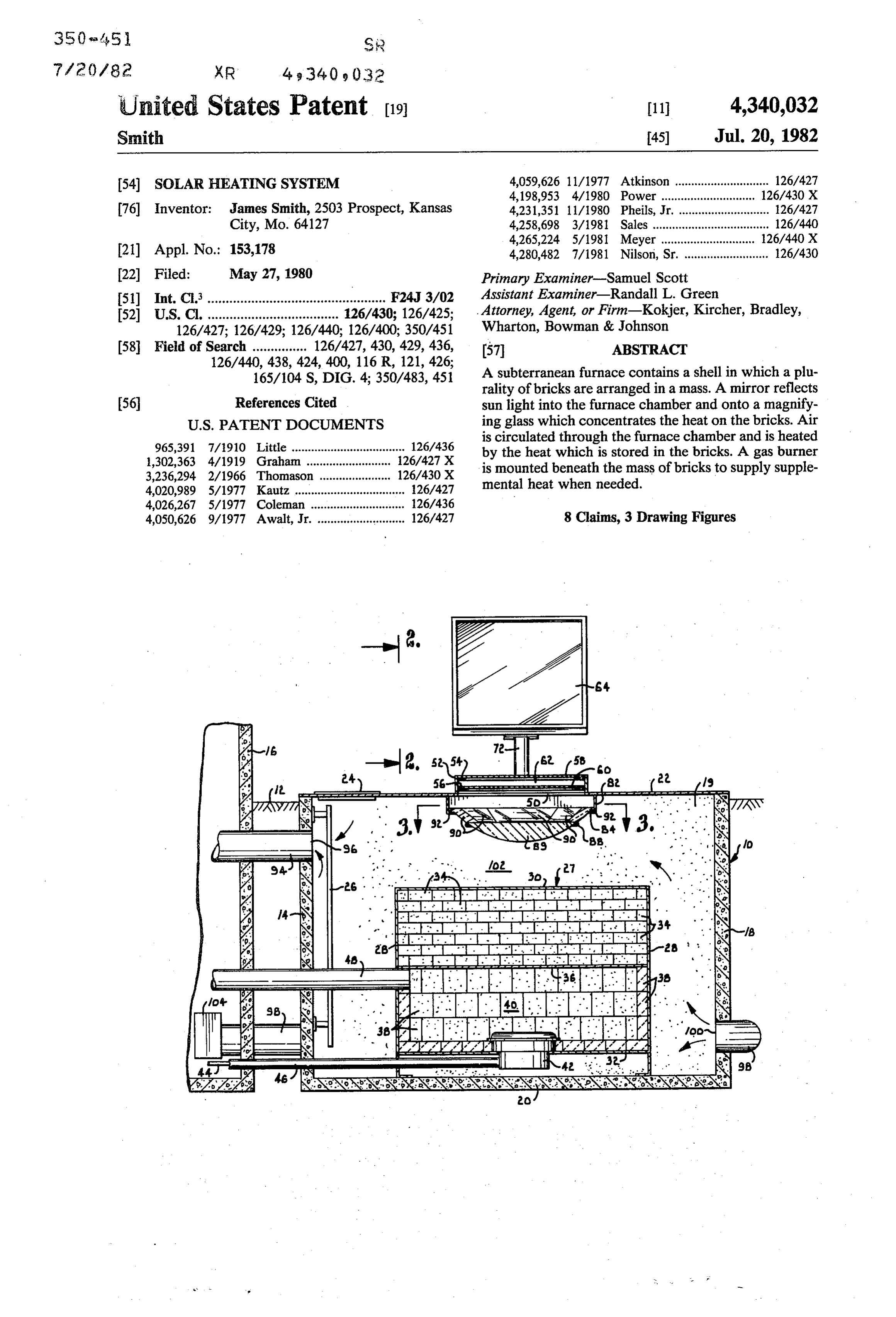
Page 1 — bibliographic record
United States Patent (19) 11 4,340,032 Smith 45) Jul. 20, 1982 (54) SOLAR HEATING SYSTEM 4,059,626 11/1977 Atkinson ............................. 126/427 4,198,953 4/1980 Power...... 126/430 X 76 Inventor: James Smith, 2503 Prospect, Kansas 4,231,351 11/1980 Pheils, Jr. . ... 126/427 City, Mo. 64127 4,258,698 3/1981 Sales .................................... 126/440 4,265,224 5/1981 Meyer .......... ... 126/440 X 21) Appl. No.: 153,178 4,280,482 7/1981 Nilson, Sr. .......................... 126/430 22) Filed: May 27, 1980 Primary Examiner-Samuel Scott (51) Int. C. ................................................. F24J 3/02 Assistant Examiner-Randall L. Green (52) U.S. C. .................................... 126/430; 126/425; Attorney, Agent, or Firm-Kokjer, Kircher, Bradley, 126/427; 126/429; 126/440; 126/400; 350/451 Wharton, Bowman & Johnson (58) Field of Search ............... 126/427, 430, 429, 436, 57 ABSTRACT
165/104 S, DIG. 4; 350/483, 451 A subterranean furnace contains a shell in which a plu rality of bricks are arranged in a mass. A mirror reflects (56) References Cited sun light into the furnace chamber and onto a magnify
965,391 7/1910 ... 126/436 is circulated through the furnace chamber and is heated 1,302,363 4/1919 126/427 X by the heat which is stored in the bricks. A gas burner
is mounted beneath the mass of bricks to supply supple 4,020,989 5/1977 Kautz .......... ... 126/427 mental heat when needed.
4,026,267 5/1977 Coleman ..... ... 126/436 4,050,626 9/1977 Awalt, Jr. ........................... 126/427 8 Claims, 3 Drawing Figures
OPP
. dealisteria
SEERIAEEEEE
Page 2
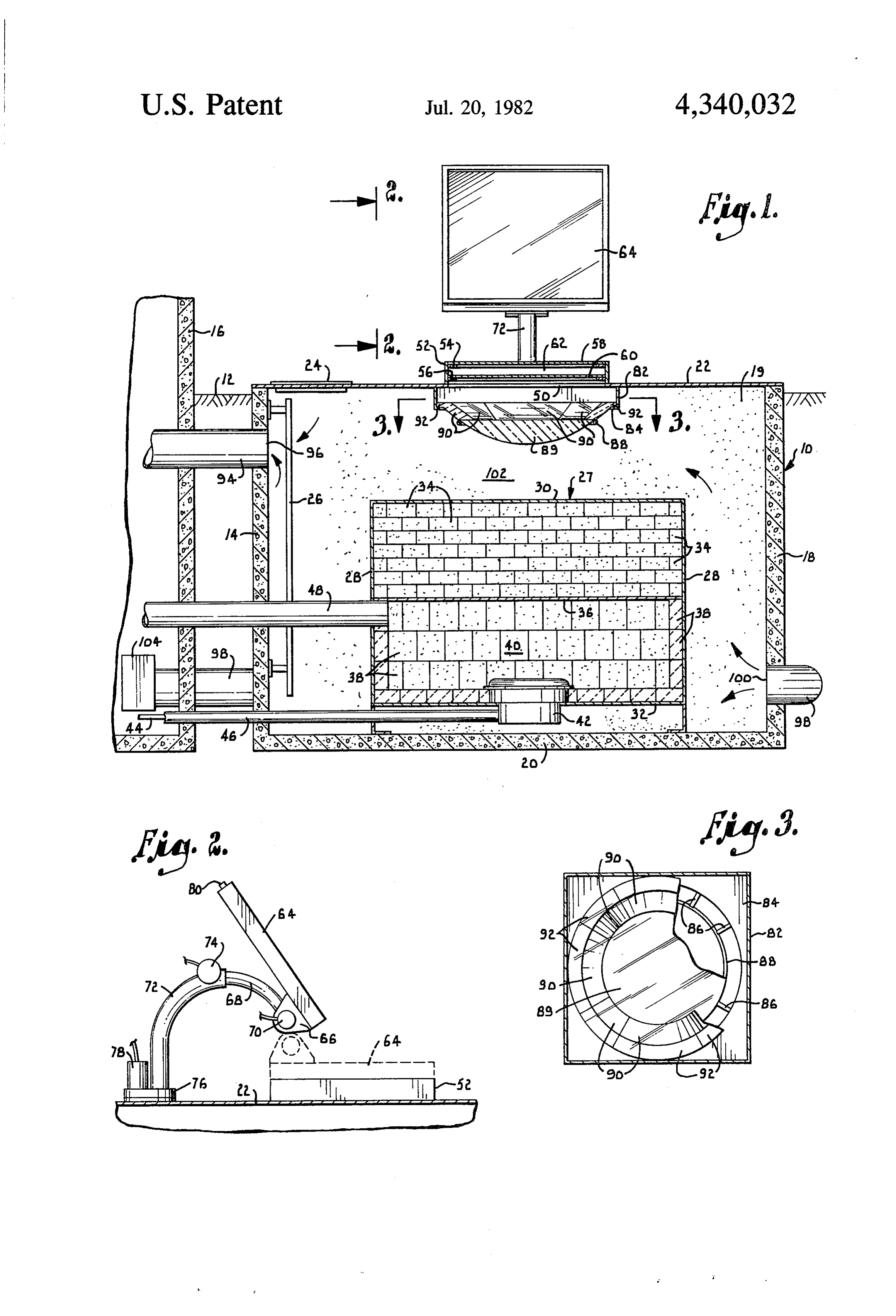
Drawing sheet — no readable text.
Page 3
arrows, with portions broken away for illustrative pur
With initial reference to FIG. 1, numeral 10 generally
BACKGROUND AND SUMMARY OF THE designates a furnace which is recessed below the INVENTION ground level 12. An inner concrete side wall 14 of the This invention relates generally to heating apparatus furnace is spaced a short distance outwardly of one of and deals more particularly with a solar heating system An the side walls 16 of the building which is to be heated. having improved heat storage and a back-up burner for opposite or outer concrete side wall 18 is spaced supplemental heating. outwardly of wall 14, and two additional concrete walls One of the principal problems associated with all 10 lar 19 extend between walls 14 and 18 to define a rectangu solar energy systems is their lack of capability to supply chamber within the furnace compartment. A con adequate energy at times when there is a prolonged lack crete bottom panel 20 forms the bottom of the furnace. of sunshine, i.e., during extended periods of cloudiness. panel 22toplocated
The of the furnace is covered by a horizontal top at or sightly above the ground level 12.
In the past, it has not been possible to economically 15 Access to the interior of the furnace chamber is pro store enough energy to compensate for the cloudy peri ods which inevitably occur in most areas. Conse vided by a manhole opening in panel 22 which is nor quently, it has been necessary to provide a conventional mally closed by a manhole cover 24. A ladder 26 is mounted to the side wall 14 at a location below the furnace for heating on those days when the solar heat ing system is unable to supply sufficient heat. This re 20 manhole.
nace
In a preferred form of the invention, the fur chamber is approximately 6 feet deep, 15 feet long sults in the need for a complete conventional furnace and 10 feet wide.
system and associated duct work in addition to the solar side of the buildingIt inis preferably located on the south order to be exposed to the sun heater, and the equipment costs are prohibitive. Fur during the winter months.
thermore, the conventional furnace must operate more the furnace to minimize theThe concrete walls insulate heat loss.
than is desirable due to the lack of effective storage of 25 Mounted within furnace 10 is a metal shell 27 having the heat which is derived from the solar heater. four side walls 28, a top panel 30 and a bottom panel 32. It is the primary object of the present invention to The provide a solar heating system which is constructed and metalshell or 27 is gas tight and may be constructed of sheet any other suitable substance having good heat arranged to store heat more effectively than the systems conductive properties. The lower ends of the side pan which have been proposed in the past. 30 els 28 engage the bottom panel 20 of the furnace. The Another object of the invention is to provide a solar heating system having a back up burner which is incor bottom of the panel 32 of the shell is spaced above the bottom furnace. The side panels 28 are spaced well in porated directly into the system in order to supply sup wardly of the sides of the furnace, while the top panel plemental heat when needed. Incorporation of the back 30 is spaced well below the top of the furnace. Shell 27 up burner directly into the solar heating system makes 35 is preferably located centrally on floor panel 20. possible the use of common components such as duct A plurality of bricks 34 are arranged in a mass within work and blowers. As a result, there is no need for a the top portion of shell 27. The bricks are located on top separate complete furnace system to provide back up of a horizontal partition 36 which extends between the heating capacity, and the equipment costs are reduced side walls of the shell at a location intermediate their accordingly. 40 heights. As an alternative to the bricks, concrete blocks Yet another object of the invention is to provide a or any other suitable elements having good heat retain solar heating system which is improved in its ability to ing characteristics may be employed. effectively collect and extract heat. A controlled mirror The inner surfaces of the side walls of the shell and serves to reflect sunbeams into the furnace and onto a the upper surface of bottom panel 32 are lined by bricks large magnifying glass which concentrates the heat on a 45 38 or other heat retaining elements. An open cavity 40 mass of bricks located within the furnace. is presented within the lower portion of the shell below An additional object of the invention is to provide a partition 36 in order to provide a combustion chamber solar heating system which is simple and economical to for a conventional gas burner 42. The burner is mounted construct and install and which lends itself to connec to bottom panel 32 of the shell and has a gas line 44 tion with conventional duct work. 50 leading to it concentrically within an air supply conduit Other and further objects of the invention, together 46. Line 44 connects with a source of gas, while conduit with the features of novelty appurtenant thereto, will 46 is open at its inner end in order to permit air to be appear in the course of the following description. drawn through it and delivered to burner 42 for com DETALED DESCRIPTION OF THE bustion purposes. The open end of conduit 46 is located 55 within the building.
INVENTION
The combustion gases from burner 42 are exhausted
In the accompanying drawing which forms a part of from cavity 40 through an exhaust pipe 48 which con the specification and is to be read in conjunction there nects at one end with cavity 40. The exhaust pipe 48 with and in which like reference numerals are used to extends through the side wall 14 of the furnace and also indicate like parts in the various views: 60 through the building wall 16 and connects with a chim FIG. 1 is a fragmentary sectional view taken on a ney or flue (not shown) in order to deliver the combus vertical plane through the furnace compartment of a tion gases thereto.
heating system constructed in accordance with a pre The top panel 22 of the furnace has a central rectan ferred embodiment of the present invention; gular opening 50 through which sunbeams may pass FIG. 2 is a fragmentary view taken generally along 65 into the furnace. Surrounding opening 50 is an upstand line 2-2 of FIG. in the direction of the arrows; and ing flange 52 having a pair of vertically spaced lips 54 FIG. 3 is a fragmentary sectional view taken gener and 56 projecting inwardly therefrom. The lips 54 and ally along line 3-3 of FIG. 1 in the direction of the 56 support respective transparent panels 58 and 60
Page 4
which are spaced apart from one another by an air 100 and 96. An air space 102 is presented within furnace pocket 62. Each of the panels 58 and 60 is constructed 10 exteriorly of shell 27 to accommodate a flow of air of glass or another transparent insulating material. The passing between conduits 98 and 94. A conventional air pocket 62 provides additional insulation which im blower or fan 104 forces air to flow through conduit 98 pedes the leakage of heat out of the furnace. and space 102 into the return conduit 94, as indicated by A mirror 64 is mounted on top of the furnace in orde the directional arrows in FIG. 1. In operation of the to reflect sunlight toward the glass panels 58 and 60. As furnace, the rays which encounter mirror 64 are re best shown in FIG. 2, mirror 64 is provided with lugs 66 flected through the glass panels 58 and 60 toward the which are connected with a curved mounting arm 68 magnifying glass 89. The magnifying glass serves as a for pivotal movement about a horizontal axis. A con 10 lens which focuses or concentrates the heat of the sun ventional electric motor 70 serves to pivot mirror 64 on on the bricks 34 contained within shell 27, thereby heat arm 68 about a horizontal axis. The mounting arm 68 is ing the bricks. The air which is forced out of end 100 of received in a curved tube 72 and is extensible and re the return conduit 98 passes through space 102 and tractable relative to the tube. A conventional electric adjacent shell 27, thereby effecting heating of the air motor 74 acts through a suitable drive mechanism (not 15 before it enters conduit 94 for delivery to the area that shown) to extend and retract arm 68. is to be heated. The lenses 90 mounted on the peripheral The lower end of tube 72 connects with a base 76 shoulder of magnifying glass 89 assist in focusing the which is mounted on panel 22 in a manner to rotate heat on shell 27. The bricks 34 retain heat for an ex about a vertical axis. A conventional electric motor 78 tended period of time so that they continue to heat the effects rotation of the base in order to rotate the mirror. 20 circulating air at night and at other times when there is The operation of the electric motors 70, 74 and 78 is little or no sun light entering the unit. The use of bricks controlled by a photoelectric sensing device 80 or other elements having good heat retention character mounted on top of mirror 64. The control arrangement istics thus provides improved heat storage capacity for is conventional and functions in a well known manner the system, and there is ordinarily no need for supple to maintain the reflective surface of mirror 64 facing in 25 mental heat.
a direction to reflect maximum sunlight toward panels If there are occasions when the solar energy fails to 58 and 60 at all times. The photoelectric sensing device provide sufficient heat, burner 42 may be operated to 80 is aimed in a direction oriented at 45 to the reflective burn gas within cavity 40 in order to provide supple surface of the mirror and controls the motors such that mental heat to the bricks 34. Since the same duct work device 80 is maintained to always directly receive the 30 is used for the solar heating system and for distributing sunlight. In this manner, mirror 64 tracks the sun across the heat generated by burner 42, there is no need for a the sky and is continually maintained in an orientation complete back up furnace system, and the equipment to reflect the maximum amount of light and heat toward costs are reduced considerably in comparison to sys the glass panels 58 and 60. At night, mirror 64 is main tems requiring a complete back up furnace system. tained in the position shown in broken lines in FIG. 2 35 Location of the furnace beneath the ground level 12 wherein it covers opening 50 to prevent heat loss. increases the efficiency of the system because the sub A metai band 82 extends downwardly from panel 22 terranean region is warmer than the above ground re at a location slightly outwardly of opening 50. The gion during the winter. Therefore, the relatively high lower edge of band 82 is provided with an inturned temperatures surrounding furnace 10 provide natural flange 84 having a generally circular inside edge por 40 insulation which minimizes the heat loss from the fur tion. Extending inwardly and downwardly from the 2CC.
edge of flange 84 are a plurality of spaced apart bars 86 From the foregoing, it will be seen that this invention (FIG. 3) which carry a ring 88 at their lower ends. A is one well adapted to attain all the ends and objects magnifying glass 89, is mounted on ring 88 such that the hereinabove set forth together with other advantages periphery of the magnifying glass rests on top of the 45 which are obvious and which are inherent to the struc ring. A plurality of small lens elements 90 extend up ture.
wardly and outwardly at an angle from a flat shoulder It will be understood that certain features and sub formed on the periphery of the magnifying glass 89. The combinations are of utility and may be employed with lens elements 90 are supported on glass 89 and on bars out reference to other features and subcombinations. 86 and have lips 92 at their upper portions which rest on 50 This is contemplated by and is within the scope of the top of flange 84 to provide additional support. The claims.
magnifying glass 89 is located centrally above shell 27 Since many possible embodiments may be made of and is spaced therefrom. the invention without departing from the scope thereof, Heated air is delivered from furnace 10 to the area it is to be understood that all matter herein set forth or which is to be heated through a conduit 94 having an 55 shown in the accompanying drawings is to be inter open end 96 located adjacent the inner wall 14 of the preted as illustrative and not in a limiting sense. furnace. Conduit 94 extends through the building wall claim:
16 to connection with conventional duct work (not 1. Heating apparatus comprising: shown) which delivers the heated air to registers lo a plurality of walls located beneath the ground sur cated in the various rooms of the structure. Air which is 60 face and defining therebetween an enclosed cham to be heated by the furnace is delivered thereto through er located remotely of an area to be heated; a return conduit 98 which connects with conventional a substantially enclosed shell in said chamber spaced duct work (not shown) that extends from one or more inwardly of said walls to provide a space in the return registers. The return conduit 98 extends through chamber exteriorly of said shell for accommodat wall 16 and beneath the ground around furnace 10, 65 ing air to be heated;
extending into the furnace through the outer wall 18. a plurality of heat retaining elements arranged in a Conduit 98 has an end 100 located adjacent to wall 18 mass in said shell, said elements being adapted to such that shell 27 is located between the conduit ends retain heat;
Page 5
an air tight cavity located immediately beneath said 3. Apparatus as set forth in claim 2, wherein said heat heating retaining elements; retaining elements comprise bricks. a transparent panel on said chamber located to direct 4. Apparatus as set forth in claim 2, wherein said sun beams into the chamber; return conduit connects with said chamber at a location remote from the area to be heated and said delivery lens means for concentrating the sun beams passing 5 conduit through said panel onto said shell for heating of connects with said chamber at a location in said heat retaining elements; proximity to the area to be heated, said mass of heat retaining elements being located intermediate the cham a burner in said cavity operable to selectively apply ber whereby air passing through the chamber from said supplemental heat to said shell to heat said heat 10 return retaining elements; conduit to said delivery conduit encounters said
an exhaust conduit communicating with said caivity 5. Apparatus as set forth in claim 2, including a sec for exhausting the combustion gases of the burner; ond transparent panel spaced below the first mentioned a cold air return conduit communicating at one end panel and separated therefrom by an air space, said with the area to be heated and at the other end with 15 second panel being constructed of an insulating mate said space to deliver return air thereto; rial.
a hot air delivery conduit communicating at one end 6. Apparatus as set forth in claim 2, wherein said with said space and at the other end with the area magnifying glass is a circular lens member having a to be heated to deliver hot air thereto; and curved surface and a circular periphery, and including a means for effecting passage of air through said return 20 plurality of lens elements on the periphery of said lens conduit and said space to said delivery conduit to member oriented to extend outwardly and upwardly direct hot air to the area to be heated. therefrom.
2. A heating apparatus comprising: 7. Apparatus as set forth in claim 2, including: a plurality of walls providing a substantially enclosed a second transparent panel spaced between the first chamber beneath the ground surface at a location 25 mentioned panel and said magnifying glass, said remote from an area to be heated; second panel being constructed of an insulating a substantially enclosed shell disposed in said cham material and being separated from the first men ber and having walls spaced inwardly of the walls tioned panel by an air space; of said chamber to provide a space for passage of 30 a mirrorbeams mounted above said panels to reflect sun toward same; and air to be heated between the shell walls and cham ber walls; means for controlling the orientation of said mirror a plurality of heat retaining elements arranged in a such that the sun beams encountering same are reflected toward said panels and said magnifying mass within said shell, each of said elements being glass.
constructed of a material adapted to retain heat; 35 8. Heating apparatus comprising:
a cavity presented within said shell adjacent the bot an enclosed chamber defined between walls located tom thereof at a location beneath said heat retain beneath the ground surface remote from an area to ing elements; be heated;
a transparent panel constructed of an insulating mate a substantially enclosed shell disposed in said cham rial and located adjacent an upper portion of said 40 ber and defined within walls spaced inwardly of chamber at a position wherein the panel is exposed the walls of said chamber to provide a space for to the sun to direct sun beams into the chamber; passage of air to be heated between the shell walls a magnifying glass supported within said chamber and chamber walls, said shell presenting a cavity beneath said transparent panel at a location to re adjacent the bottom thereof; ceive the sunbeams passing through the panel, said 45 a mass of heat retaining material in said shell above magnifying glass concentrating the beams on said said cavity;
mass of heat retaining elements for heating of same; a transparent panel located adjacent an upper portion a burner mounted in said cavity and operable to burn of said chamber at a position to direct sun beams fuel for supplemental heating of said heat retaining 50 lensintomeans the chamber;
for concentrating the sum beams passing elements; through said panel onto said mass of heat retaining an exhaust conduit communicating with said cavity material for heating of same; and extending out of said chamber to exhaust the supplemental heating means in said cavity operable to combustion gases of said burner; generate heat for supplemental heating of said mass a cold air return conduit extending from the area to 55 of heat retaining material; be heated to said chamber to deliver air thereto; a cold air return conduit extending from the area to a hot air delivery conduit extending from said cham be heated to said space to deliver air thereto; ber to the area to be heated to deliver hot air a hot air delivery conduit extending from said space thereto; and to the area to be heated to deliver hot air thereto; means for passing air through said return conduit and 60 and chamber to said delivery conduit for delivery to means for effecting passage of air through said return the area to be heated, whereby the air passing and delivery conduits and said space, whereby the through said chamber is heated by the heat retain air passing through said space is heated prior to ing elements prior to entering said delivery con entering said delivery conduit.
Provenance
- Collection
- Patents citing this work
- Pages
- 5
- Method
- pdftotext (the PDF's own text layer) + pdftoppm 300dpi page scans
- Patent office record
- patents.google.com →
- Source
- Google Patents citing-documents table
- Assignee
- James Smith
- Inventors
- James Smith
- Published
- 1982-07-20
- Transcribed from
- patentimages.storage.googleapis.com →