patent · US4231351
Method and apparatus for solar heating a building
4 November 1980
Page 1 — bibliographic record
United States Patent (19) (11) 4,231,351 Pheils, Jr. 45) Nov. 4, 1980
54) METHOD AND APPARATUS FOR SOLAR 3,986,306 10/1976 Trannoy ................................... 52/79 HEATING A BUILDING 4,010,731 3/1977 Harrison ... ... 126/400X 4,029,258 6/1977 Groth ........ a---- - - 237/1 A
76) Inventor: David R. Pheils, Jr., 5814 Rye Mill 4,051,891 10/1977 Harrison ........ ... 237/1 AX Ct., Toledo, Ohio 43611 4,051,999 10/1977 Granger et al. ..................... 237/1 A
(21) Appl. No.: 51,385 Primary Examiner-Albert J. Makay 22 Filed: Jun. 25, 1979 Assistant Examiner-William E. Tapolcai, Jr. Attorney, Agent, or Firm-Charles R. Schaub
Related U.S. Application Data
doned. This invention relates to a building having a central unit defined and enclosed by a peripheral main section 51) Int. C. ................................................. F24J 3/02 therearound. The central unit has a transparent roof to 52 U.S. C. .................................... 126/419; 126/427; permit the passage of solar energy therethrough to heat 126/429; 126/430; 52/169.11; 52/79.6 the air and other contents of a courtyard thereunder. (58) Field of Search .................... 52/79.6, 79.2, 236.2, The central unit also has a heat storage mass under the 52/169.6, 169.11, 200; 126/419, 427, 429, 430, courtyard for storage and retrieval of energy during
selected periods. The edges of the dome rest upon the (56) References Cited walls of the main section defining the courtyard. Such
3,455,069 7/1969 Keyes ................................ 52/200 X storage section containing the heat storage mass. 3,894,369 7/1975 Schmitt et al. ....... - - - -- - - - - 52/173
3,983,929 10/1976 Thomason et al. .............. 126/400X 6 Claims, 6 Drawing Figures
Page 2
Drawing sheet — no readable text.
Page 3
Drawing sheet — no readable text.
Page 4
THERMostAT tal
LOCATE IN
COURTYARD
DFFERENTAL
DFFERENTAL
THERMOSTAT 83
THERMOSTAT
SWITCH AND
senson 9 (9 SENSOR W If THERMOSTAT
CONTACTS
THERMOSTAT #86
LOCATE IN MAN
DFFERENTAL
THERMOSAT is 87
SECT ON OF HOUSE
is 89 & 65 ELEMENT #90, # 7, 75 & 77
Page 5
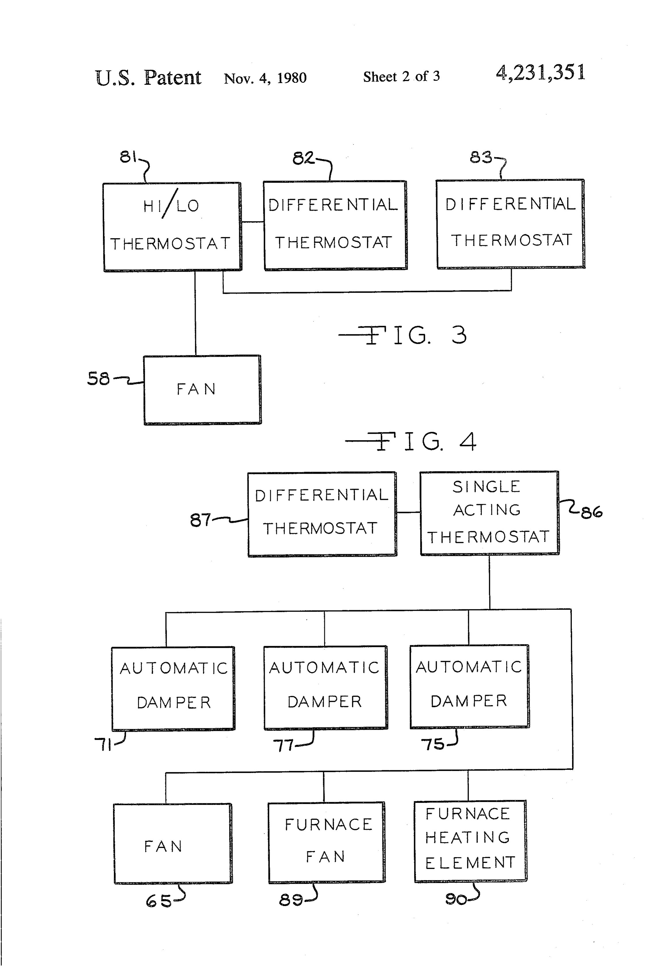
FIG. 3 is a schematic diagram of the control system
METHOD AND APPARATUS FOR SOLAR for controlling the movement of air from the energy HEATING A BUILDING collection section through the energy storage section. FIG. 4 is a schematic illustration of the system for
This is a continuation of application Ser. No. 788,115, 5 controlling the movement of the air from the main sec filed Apr. 8, 1977, now abandoned. tion alternately through the energy collection section
BACKGROUND OF THE INVENTION
and the alternate heat source for additionally heating the air.
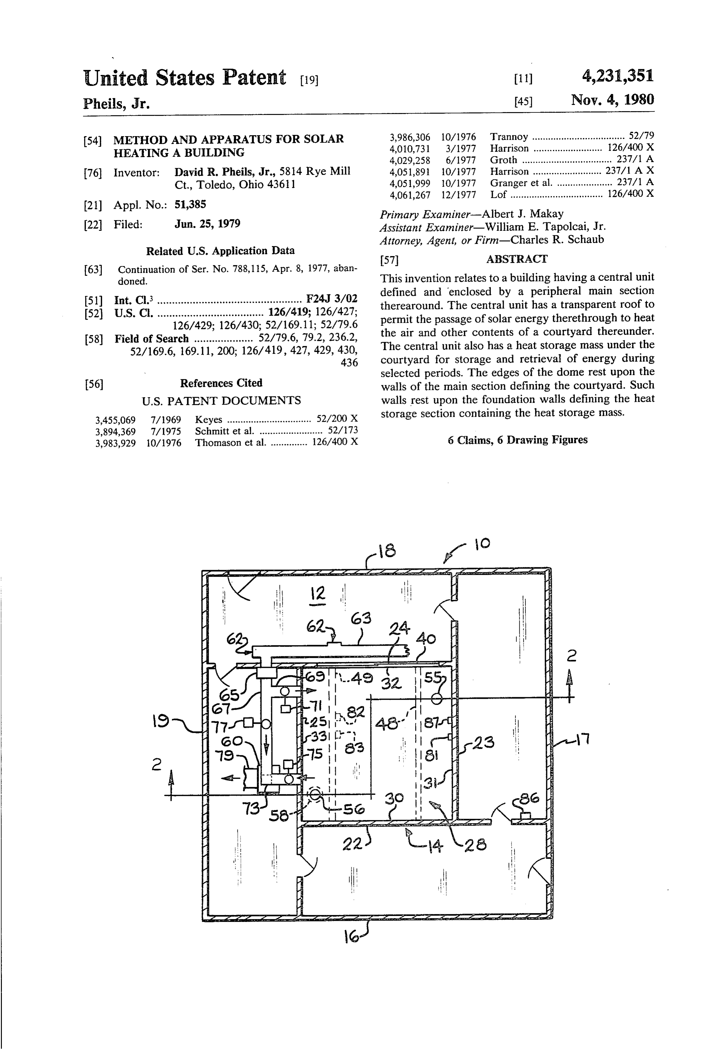
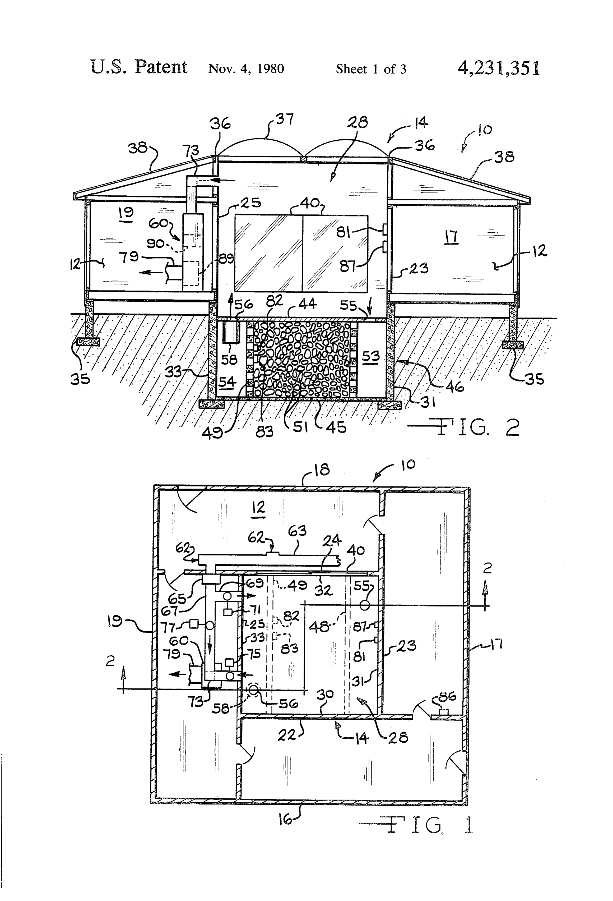
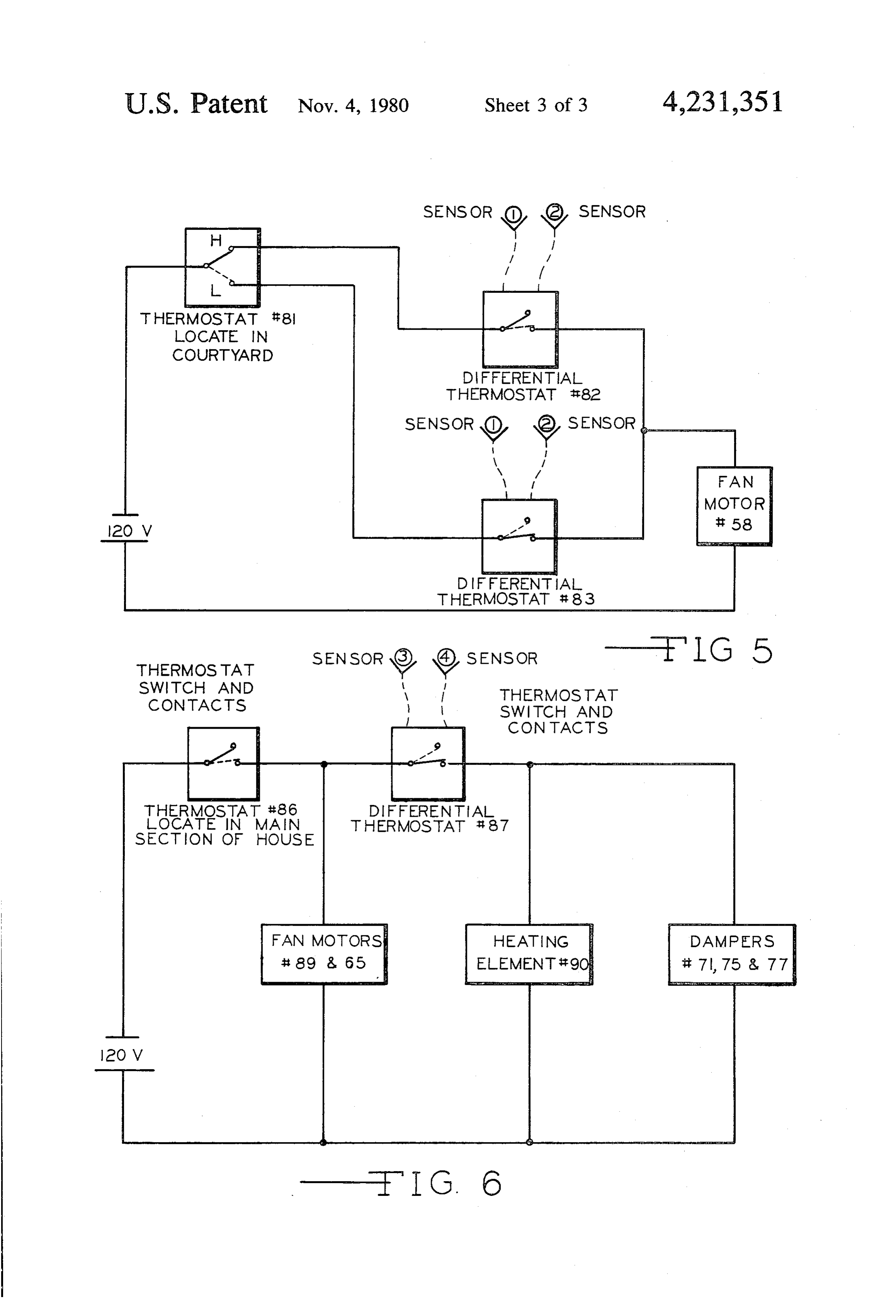
A building or dwelling having an efficient solar heat FIG. 5 is a wiring diagram of the control system for ing system and an aesthetically pleasing design whose 10 controlling the movement of air from the energy collec cost is not economically unreasonable has been the goal tion section through the energy storage section. of many efforts. FIG. 6 is a wiring diagram of the system for control As a prerequisite to economical use of solar energy ling the movement of the air from the main section for heating, it is necessary to provide a low-cost, effi alternately through the energy collection section and cient, and trouble-free solar energy collector to capture the alternate heat source for additionally heating the air. such energy in the form of heat. Also, it is necessary to DESCRIPTION OF THE INVENTION provide a low-cost, trouble-free, and effective heat stor age and retrieval means to store the heat trapped by the As shown in FIGS. 1 and 2, building or dwelling 10 collector and to deliver the heat to the building from the comprises a main section 12 enclosing a central unit or heat storage mass when needed. section 14. The main section can be constructed on-site To reduce the amount of heat loss to the ambient or can be built from prefabricated sections or modules environment, the window area of the exterior walls of 16, 17, 18, and 19 around the periphery of the central the structure should be kept to a minimum or even unit. The dual purpose central unit functions as a solar heating system as well as occupiable living space.
eliminated. But the lack of exterior light and viewing, 25 Inner walls 22, 23, 24, and 25 of main section 12 are generally, provides a less than aesthetically pleasing environment. Some building designs have minimized tion arranged to enclose and define the solar energy collec the external window area of the building and have pro 24, and section 28 of central unit 14. The inner walls 22, 23, vided a sky-light for heating an enclosed area and aes 25 can be substantially co-planar with and can thetic purposes. For example, see U.S. Pat. Nos. 30 centralrest upon foundation walls 30, 31, 32, and 33 of the 3,894,369 and 3,815,299 by Schmitt et al. and Sorenson section can unit 14, respectively. The balance of the main et al., respectively. Others have employed various solar rest upon peripheral foundation 35. Central roof section or dome 37 covering the central collection and heating systems of one type or another in unit can be a single buildings in an effort to conserve our natural resources. having a plurality ofarched dome, or the like, or a dome arches as shown in FIG. 2. The
For example, see U.S. Pat. Nos. 3,254,702 and 3,412,728 35 peripheral edge 36 of dome 37 can rest upon the inner by Harry E. Thomason. Yet, the need for a low-cost, walls 22, 23, 24, and 25. The peripheral edge 36 of dome efficient, aesthetically pleasing building having solar 37 can be contiguous with main roof 38 and sealed heating persisted. therealong to provide a suitable weatherproof roof for SUMMARY OF THE INVENTION the entire structure.
40 The dome can be a transparent acrylic sheet to permit
According to the principles of this invention, there is the passage of solar energy therethrough. That is, the provided a building comprising a solar energy collec central roof or dome is adapted to permit the passage of tion section; a main section having inner walls enclosing solar energy therethrough to heat the air and other the energy collection section; an energy storage section contents of solar energy collection section 28. Further under the energy collection section, the storage section 45 more, it is believed that the planar area of the transpar being defined by foundation walls, said inner walls rest ent section of the roof should be from 25 to 30 percent ing upon said foundation walls; a roof covering the of the planar area of main section 12 of the building to energy collection section adapted to permit the passage provide a suitably sized solar heat collection system for of Solar energy therethrough to heat the energy collec geographical areas such as Ohio and the like. tion section, said roof having the peripheral edge resting 50 Inner walls 22, 23, 24, and 25 can be equipped with upon said inner walls; a floor spaced from the roof to sliding glass doors 40 and the like to provide viewing separate the storage section from the collection section; and access to the courtyard or energy collection section and means for selectively moving air within the energy 28 from the other section or sections of the building. collection Section through the energy storage section in Thus, the energy collection section can be isolated from a heat-exchanging relationship. Also provided is a con- 55 the remainder of the building when desired. trol system for selectively directing and moving the air A floor or planar member 44 is joined at the founda within the building. tion walls 30, 31, 32, and 34 or inner walls 22, 23, 24, and Therefore, it is an object of this invention to provide 25 to separate the central unit 14 into an energy collec a building having an inhabitable solar energy collection tion section 28 and energy storage section or heat stor means enclosed by the main section of the building. 60 age means 46. Preferably, the floor 44 is joined to foun Other objects and advantages of this invention will be dation walls 30, 31, 32, and 33.
obvious and explained by reference to the accompany Floor 44, foundation walls 30, 31, 32, and 33 and ing specification and drawings. subfloor 45, which is joined to the foundation walls, also DESCRIPTION OF THE DRAWINGS serve to enclose and define the energy storage section 65 46. Subfloor 45 can be equipped with a drain to remove
FIG. 1 is a plan view of the building. any moisture that may collect on the subfloor. The FIG. 2 is a sectional view taken along section line energy storage section 28 is enclosed and defined by 2-2 of FIG. . floor 44, inner walls 22, 23, 24, and 25, and dome 37. If
Page 6
desired, contiguous foundation and inner walls can be rects the heated air into the building via a network of constructed as a plurality of vertical members or walls other ducts and registers not shown. Such dampers can extending from the subfloor to the dome. be a commercially available type. A pair of foraminous or air-permeable walls 48 and 49 To control air distribution throughout the building, can extend from the subfloor 45 to floor 44 between a commercially available types of thermostats can be pair of opposed foundation walls. As such, foundation employed. In a first control system, a dual acting, or walls 22 and 24 and foraminous walls 48 and 49 provide high/low type, thermostat 81 is located in the courtyard a suitable enclosure for heat storage mass 51. Such a or energy collection section 28. Thermostat 81 can be heat storage mass can consist of commercially available located on inner wall 23, approximately midway be crushed and washed rock of a size sufficient to provide 10 tween floor 44 and the peripheral edge 36 of dome 37 to a suitable heat sink and to readily permit air flow there obtain an average temperature of the air within the through. courtyard. A pair of differential thermostats 82 and 83 The first foraminous wall 48, as shown in FIGS. 1 and can be located within the energy storage section 46. 2, is parallel to and spaced from foundation wall 31 to Thermostats 82 and 83 can be in contact with the heat provide a first zone 53 therebetween. Similarly, a sec 15 storage mass 51. Fan 58 can be electrically intercon ond foraminous wall 49 can be parallel to and spaced nected with thermostats 81, 82, and 83 to control the from foundation wall 33 to provide a second zone 54 operation of the fan 58. The differential thermostats 82 therebetween. and 83, as is well known in the art, each include a tem A first passageway 55 extends through floor 44 to perature sensor located in the collection section 28 and provide communication between the energy collection 20 another temperature sensor located in the heat storage section 28 and the first zone 53 of the energy storage mass 51. Thermostat 81 can operate such that it will section 46. Likewise, a second passageway 56 extends form an electrical path therethrough if the sensed tem through floor 44 to provide communication between perature is outside the predetermined range. FIGS. 3 the second zone 54 of the energy storage section 46 and and 5 show a schematic diagram and wiring diagram, the energy collection section 28. As shown in FIGS. i 25 respectively of the system for controlling the movement and 2, a fan or air moving means 58, or the like, is posi of air from the energy collection section through the tioned at passageway 56 to forcibly move air from the energy storage section. The connections and wiring for energy collection section 28 through the heat storage the thermostats, sensors and fan shown in these figures mass, and back to the energy collection section by way is well known in the solar heating art. of zones 53 and 54, foraminous walls 48 and 49, and 30 In operation, if the temperature of the air in the court passageway 55. yard 28 as sensed by the high/low thermostat 81 is The porosity of the foraminous walls can be arranged above the high temperature set point and the tempera such that a generally even air flow through the heat ture of the heat storage mass as sensed by differential storage mass over the length of the foraminous walls thermostat 82 is less than the temperature of the air in can be obtained for more efficient operation. 35 the courtyard by a preselected amount, thermostats 81 An alternate heat source 60, such as is commercially and 82 are adapted to energize fan 58 to move the air in available, forced-air type furnace, can be employed to the courtyard 28 through the heat storage mass 51. provide heat for the building if the solar heating system Thus, thermal energy can be transferred to the mass 51 should not provide enough heat to adequately heat the and stored therein.
building for whatever reason. As shown in FIGS. i and 40 If the air temperature in the courtyard as sensed by 2, the cold air return system for heat source 60 is de thermostat 81 is lower than the low temperature set signed to take advantage of the heat stored and being point of thermostat 85 and the temperature of mass 5 is collected in the central unit 14. The cold air return greater than the air temperature in the courtyard by a system withdraws air from the main section 12. As such, preselected amount, thermostats 81 and 33 are adapted cold air return registers 62 are connected to main duct 45 to energize fan 58 to move air from the courtyard 28 63, which is connected to the intake side of fan or air through mass 55, thereby warming the air moving moving means 65. The exhaust side of fan 65 is con through the mass and back to the courtyard. nected to one end of distributor duct 67. The other end In a second control system, a single acting thermostat of duct 67 is connected to alternate heat source 60 at the 86 is suitably located in the main section 12 to sense the intake port thereof. 50 air temperature therein. A differential thermostat 87 is Adjacent fan 65, exhaust duct 69 branches from dis located in the courtyard 28, generally adjacent thermo tributor duct 67 to form a passageway through the inner stat 8, to sense the air temperature therein. wall 25 from the energy collection section 28 to distrib As shown in FIGS. 1 and 2, alternate heat source 60 utor duct 67. Automatic damper 71 is located within the is forced-air type having a fan 89 and a heating element exhaust duct 67 to selectively control the air flow from 90. FIGS. 4 and 6 show a schematic diagram and wiring the energy collection section to distributor duct. diagram, respectively of the second control system for Damper 71 can also be of the manually operated type. controlling the movement of air from the main section Adjacent heat source 60, intake duct 73 branches alternately through the energy collection section and iron distributor duct 67 to form a passageway through the alternate heat source for additionally heating the air. inner wall 25 from the energy collection section 28 to 60 The connections and wiring for the thermostats, sensors distributor duct 67. An automatic damper 75 is located and fans shown in these figures are well known in the within intake duct 73 to selectively control the air flow art.
therethrough. Damper 75 can also be a manually oper In operation, if the temperature of the air in main ated type. Automatic damper 77, located within distrib section 12 as sensed by thermost at 86 is below a prede utor duct 67 between exhaust duct 69 and intake duct 65 termined set-point value and the temperature of the air 73, selectively controls the air flow therethrough. in the courtyard 28 is greater than the predetermined Damper 77 can also be a manually operated type. Main set-point value of thermostat 86, thermostats 86 and 87 heat supply duct 79 extending from heat source 60 di are adapted to energize dampers 7 and 75 to assume the
Page 7
"open' position. When a damper is "open,' air is per air having a temperature greater than the remainder of mitted to flow past the damper, and when "closed' air the air in the energy collection section 28 when the air is not permitted to flow past the damper. At that time, is being moved out of the storage section in the energy damper 77 is energized to move to the "closed' posi retrieval mode, that is, when the heat is being released tion, and fans 65 and 89 are also energized to move the from the storage mass to the air. Not all the air will be air therethrough. Thereby, air is withdrawn from main ingested by the intake duct, such that the remainder of section 12 and moved into courtyard 28 to mix and be the mass of air of the stream will mix with and warm the warmed by the air therein via duct 62 and fan 65, and remaining air in the courtyard.
the air in the courtyard 28 is moved by fan 89 back into Suitable ducts and dampers (not shown) can be em main section 12 via duct 79. At this time, the heating 10 ployed to move fresh air from the exterior of the struc element 90 is not energized, that is, heating the air ture into the courtyard and exhaust stale air from the therearound, since the building can be sufficiently courtyard as desired.
heated by the warmer air in the courtyard. Fan 65 is not It will be appreciated that variations and construc absolutely necessary to suitably move the air, as long as tional features, as well as substitution of equivalent the sliding glass doors to the courtyard are closed. 15 components, can be undertaken without departing from However, to achieve a more even heat distribution the spirit and scope of the present invention. throughout main section 12, it is prefered that fan 65 be I claim:
employed. 1. A building comprising:
If the air temperature in the main section 12 as sensed a plurality of sections, having walls arranged to en by thermostat 86 is below the preselected set-point 20 close a central unit, said central unit having a value of thermostat 86 and the temperature of the air in courtyard bounded by a roof adapted to permit the the courtyard 28 as sensed by thermostat 87 is less than passage of solar energy therethrough to heat the the set-point value of thermostat 86, thermostats 86 and courtyard and a floor spaced from the roof; 87 are adapted to energize dampers 71 and 75 to a heat-storage section located within the central unit "close,' damper 77 to "open,' fan 89 to move air, and 25 and below said floor;
heating element 90 to heat the air moving therethrough. means for selectively moving the air within the court Fan 65 can also be energized to move air, but it is not yard through said heat storage means in a heat absolutely necessary. Thus, air within main section is exchanging relationship when the temperature of moved directly to alternate heat source 60 via ducts 63, the air at a predetermined location within said 67, and 79 and heated therein in the absence of being 30 courtyard is outside a predetermined range of tem first moved through the courtyard 28. peratures;
The above-mentioned thermostats can be commer an alternate heat source to provide heat for said sec cially available models and can be suitably electrically tions; and interconnected by commercially available conventional means for selectively moving air from said sections means to function as set forth above. For example, dual 35 through the courtyard in a mixing relationship with acting thermostat 81 and differential thermostats 82,83 the air therein before being heated by said alternate and 87 can be of the type available from the Dayton heat source when the temperature of the air at a Manufacturing Company having catalog numbers 2E preselected point in the courtyard exceeds the tem 206 and 2E 398, respectively. perature of the air being moved from the sections Alternative distributor duct 67 can be replaced by a to the alternate heat source and moves such air horizontally oriented "H' shaped duct (not shown). directly to the alternate heat source to be heated One end of the lower bar of the “H” is attached to a therein when the temperature of the air being suitable cold air return line. The other end of the lower moved from the sections to the alternate heat bar is attached to the intake side of an alternate heat source exceeds the temperature of the air at a source. Each half and end of the upper bar communi 45 preselected point of the courtyard. cates with a separate passageway communicating with 2. A building comprising:
the courtyard. Within the now vertically oriented cross a solar energy collection section; bar of the "H" shaped system, a single rotatable damper a main section having inner walls enclosing the en is adapted to direct the air flow either directly through ergy collection section; the lower bar or first vertically to half of the upper bar 50 an energy storage section under the energy collection to direct the return air from the main section into the section, the storage section being defined by foun courtyard. The air in the courtyard is then moved dation walls, said inner walls resting upon said through the other half of the upper bar to the alternate foundation walls;
heat source to be distributed to the main section without a roof covering the energy collection section adapted being heated by the heating element in the alternate 55 to permit the passage of solar energy therethrough source similar to that system shown in FIGS. 1-4. to heat the energy collection section, said roof Furthermore, it is prefered that dome 37 be of a having a peripheral edge thereof resting upon said "Thermopane' type construction. That is, a pair of inner walls;
parallel, spaced-apart sheets of transparent material a floor spaced from the roof to separate the storage form the dome. The space between the sheets can be 60 section from the collection section; suitably evacuated, thus reducing convective and con means for selectively moving air within the energy ductive heat losses through the dome. collection section through the energy storage sec Also, intake duct 73 and passageway 56 can be dis tion in a heat-exchanging relationship when the posed to provide a coherent bulk air stream from pas temperature of the air at a predetermined location sageway 56 moving upwardly to intake duct 73 through 65 within said courtyard is outside a predetermined the courtyard when the air is moved through the energy range of temperatures;
storage section 46. Such an orientation operates such an alternate heat source to provide heat for said sec that intake duct or passageway 73 ingests a bulk flow of tions; and,
Page 8
means for selectively moving air from said sections and second zones and foraminous walls cooperat through the courtyard in a mixing relationship with ing to distribute such moving air throughout the the air therein before being heated by said alternate heat storage mass;
heat source when the temperature of the air at a an alternate heat source for supplying heated air to preselected point in courtyard exceeds the temper- 5 said main section; and ature of the air being moved from the sections to means for controlling the air flow in the building such the alternate heat source and moves such air di that the air from the main section can be moved rectly to the alternate heat source to be heated through the courtyard in a mixing relationship with therein when the temperature of the air being the air therein before being heated by said alternate moved from the sections to the alternate heat 10 heat source.
source exceeds the temperature of the air at a 4. The building of claim 3 wherein one of said inner preselected point of the courtyard. walls has an air-intake passageway communicating with 3. A building comprising: the alternate heat source and the energy collection sec a solar energy collection section; tion, said air-intake passageway and said first passage a main section having inner walls enclosing the en 15 way being disposed to provide an air stream from the ergy collection section; first passageway to the air-intake passageway when the an energy storage section under the energy collection air is moved through the heat storage mass such that the section, the storage section being defined by foun air-intake passageway ingests a substantial portion of dation walls, said inner walls resting upon said such air stream before the air of the stream is distributed foundation walls; 20 throughout the collection section. a roof covering the energy collection section adapted 5. The building of claim 4 wherein the air-intake to permit the passage of solar energy therethrough passageway ingests a bulk flow of air having a tempera to heat the energy collection section, said roof ture greater than the remainder of the air in the collec being attached at and resting upon said inner walls; tion section at the level of the air-intake passageway at a floor spaced from the roof to separate the storage 25 such inner wall.
section from the collection section; 6. The method of controlling the movement of air a subfloor spaced from and below said floor contigu from an energy collection section to an energy storage ous with the foundation walls to further define the section and a main section of a building comprising: energy storage section; (a) sensing the temperature of the air within the en a first foraminous wall spaced from one of said foun 30 ergy collection section; dation walls extending from the floor to the sub (b) sensing the temperature of a heat storage mass; floor to define a first zone between the first forami (c) moving the air within the collection section nous wall and such foundation wall; through the mass when the temperature differential a second foraminous wall spaced from the foundation between the air of the collection section and the wall opposite the foundation wall defining the first 35 mass is greater than a preselected value in response zone to define a second zone between the second to items “a” and "b';
foraminous wall and the foundation wall opposite (d) sensing the temperature of the air within the main the foundation wall defining the first zone, said section; and second foraminous wall extending from the floor to (e) moving the air from the main section (i) through the subfloor, the floor having a first passageway the collection section if the temperature of the air communicating with the first zone and the collec in the collection section is greater than the prese tion section and having a second passageway com lected temperature in the main section or (ii) di municating with the second zone and the collection rectly to an alternate heat source for heating in the section; absence of moving such air through the collection a heat storage mass within the storage section and 45 section if the temperature of the air in the collec between the first and second zones; tion section is less than the preselected temperature means for selectively moving air within the energy in the main section in response to said sensings of collection section through the heat storage mass items 'a' and 'd.'
and back to the energy collection section, the first 3. x: x: - e
Provenance
- Collection
- Cited prior art
- Original PDF
- patentimages.storage.googleapis.com →
- Filed
- 1979-06-25
- Pages
- 8
- Method
- pdftotext (the PDF's own text layer) + pdftoppm 300dpi page scans
- Source
- Google Patents bibliographic record
- Granted
- 1980-11-04
- Inventors
- David R. Pheils, Jr.
- Transcribed from
- patentimages.storage.googleapis.com →