patent · US1302363
Distilling apparatus.
29 April 1919
Page 1
Drawing sheet — no readable text.
Page 2
UNITED STATES PATENT OFFICE.
FRANK ARCHIE GRAHAM, OF HARBOB SPRINGs, MICHIGAN.
DISTILLINGAPPARATUs.
1,302,363. Specification of Letters Patent. Patented Apr. 29, 1919. Application fled September 14, 1918. Serial No. 254,073.
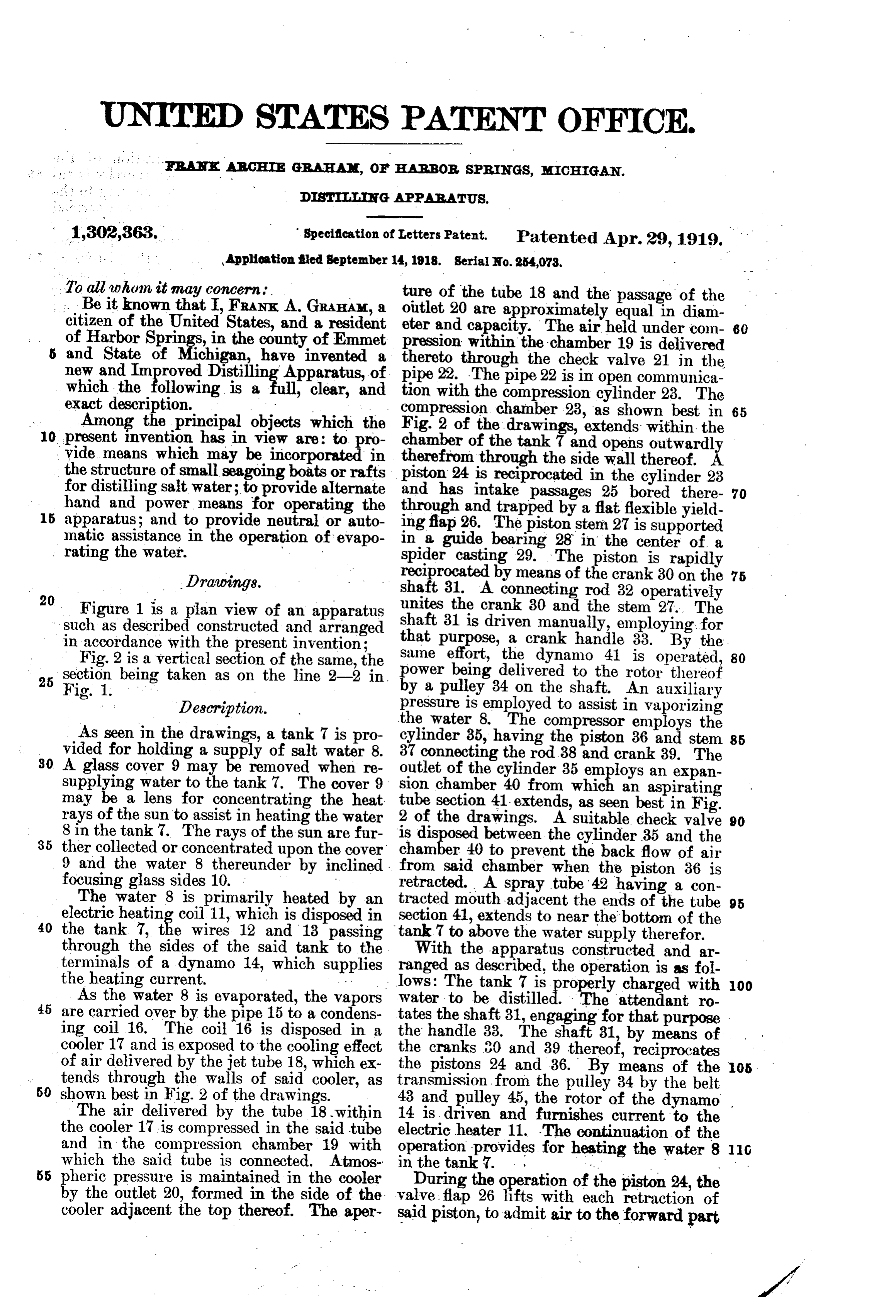
To all whom it may concern. ture of the tube 18 and the passage of the . . Beit known that I, FRANK. A. GRAHAM, a outlet 20 are approximately equal in diam citizen of the United States, and a resident eter and capacity. The air held under com 80 of Harbor Springs, in the county of Emmet pression within the chamber 19 is delivered and State of Michigan, have invented a thereto through the check valve 21 in the new and Improved Distilling Apparatus, of pipe 22. The pipe 22 is in open communica which the following is a , clear, and tion with the compression cylinder 23. The exact description. . compression chamber 23, as shown best in 65 Among the principal objects which the Fig. 2 of the drawings, extends within the 10 present invention has in view are: to pro chamber of the tank 7 and opens outwardly vide means which may be incorporated in therefrom the structure of small seagoing boats or rafts piston 24 isthrough the side wall thereof. A reciprocated in the cylinder 23 for distilling salt water; to provide alternate and has intake passages 25 bored there 70 hand and power means for operating the through and trapped by a flat flexible yield 15 apparatus; and to provide neutral or auto ing flap 26. The piston stem 27 is supported matic assistance in the operation of evapo in a guide bearing 28 in the center of a rating the water. Spider casting 29. The piston is rapidly Drawings. reciprocated by means of the crank 30 on the 75
shaft 31. A connecting rod 32 operatively
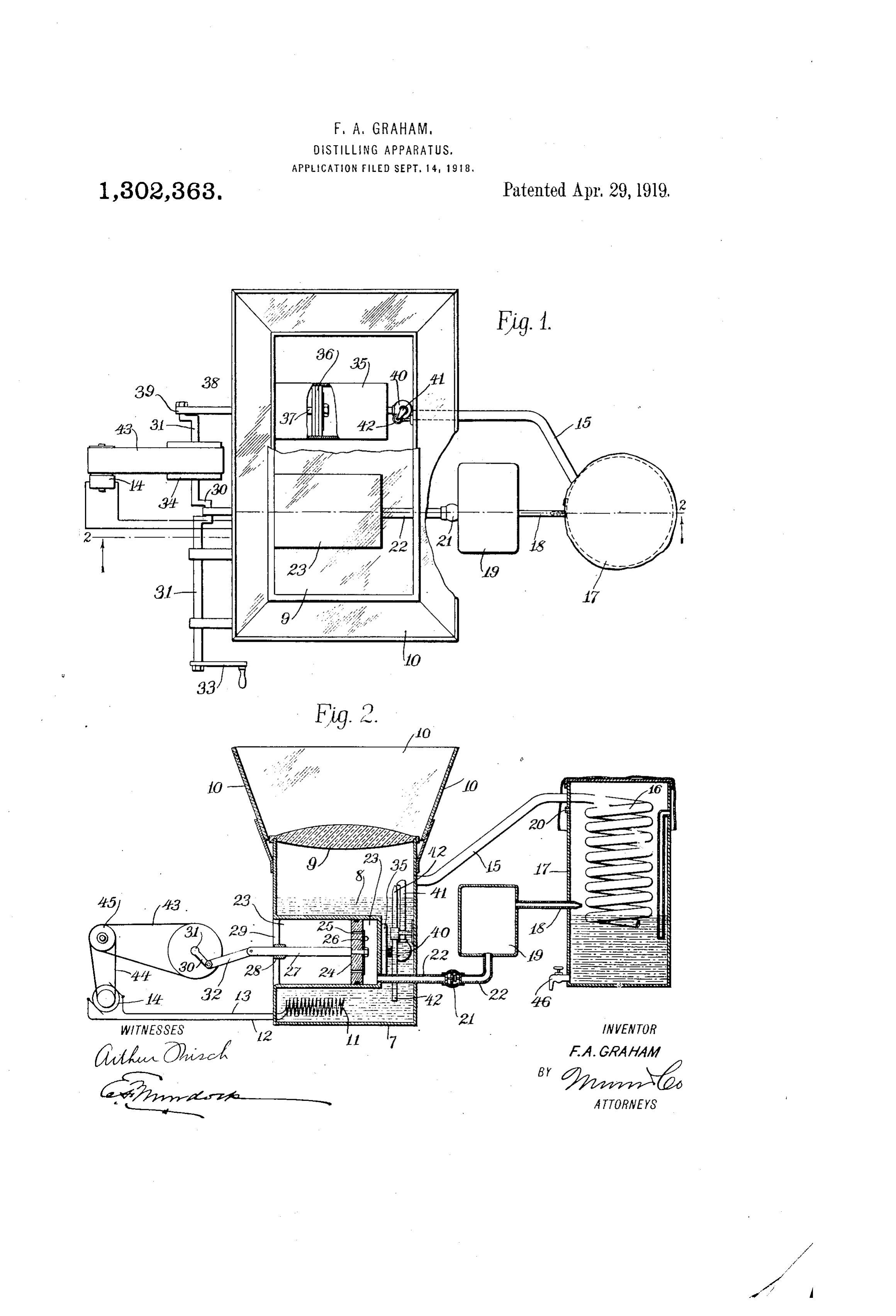
Figure 1 is a plan view of an apparatus unites the crank 30 and the stem 27. The such as described constructed and arranged shaft 31 is driven manually, employing for in accordance with the present invention; that purpose, a crank handle 33. By the Same effort, the dynamo 41 is operated, 80
Fig. 2 is a vertical section of the same, the power being delivered to the rotor thereof 25 section being taken as on the line 2-2 in by a pulley 34 on the shaft. An auxiliary
Description. pressure is employed to assist in vaporizing the water 8. The compressor employs the
As seen in the drawings, a tank 7 is pro cylinder 85, having the piston 36 and stem 85 vided for holding a supply of salt water 8. 37 connecting the rod 38 and crank 39. The 30 A glass cover 9 may be removed when re outlet of the cylinder 35 employs an expan supplying water to the tank 7. The cover 9 sion chamber 40 from which an aspirating may be a lens for concentrating the heat rays of the sun to assist in heating the water 2tube section 41 extends, as seen best in Fig. of the drawings. A suitable check valve 90 8 in the tank 7. The rays of the sun are fur is dis 35 ther collected or concentrated upon the cover between the cylinder 35 and the chamber 40 to prevent the back flow of air 9 and the water 8 thereunder by inclined. from said chamber when the piston 36 is focusing glass sides 10. retracted. A spray tube '42 having a con The water 8 is primarily heated by an tracted mouth adjacent the ends of the tube 95 electric heating coil 11, which is disposed in section 41, extends to near the botton of the 40 the tank 7, the wires 12 and 13 passing tank 7 to above the water supply therefor.
through the sides of the said tank to the With the apparatus constructed and ar terminals of a dynamo 14, which supplies ranged as described, the operation is as fol the heating current. - lows: The tank 7 is roperly charged with 100 As the water 8 is evaporated, the vapors 45 are carried over by the pipe 15 to a condens water to be distilled. The attendant ro tates the shaft 31, engaging for that purpose ing coil 16. The coil 16 is disposed in a the handle 33. The shaft 31, by means of cooler 17 and is exposed to the cooling effect the cranks 30 and 39 thereof, reciprocates of air delivered by the jet tube 18, which ex the pistons 24 and 36. By means of the 05. 50 shown through tends the walls of said cooler, as transmission from the pulley 34 by the belt best in Fig. 2 of the drawings. 43 and pulley 45, the rotor of the dynamo The air delivered by the tube 18 within 14 is driven and furnishes current to the the cooler 17 is compressed in the said tube electric heater 11. The continuation of the and in the compression chamber 19 with operation provides for heating the water 8 C which the said tube is connected. Atmos in the tank. .. 55 pheric pressure is maintained in the cooler
During the operation of the piston 24, the by the outlet 20, formed in the side of the valve flap 26 lifts with each retraction of cooler adjacent the top thereof. The aper said piston, to admit air to the forward part
Page 3
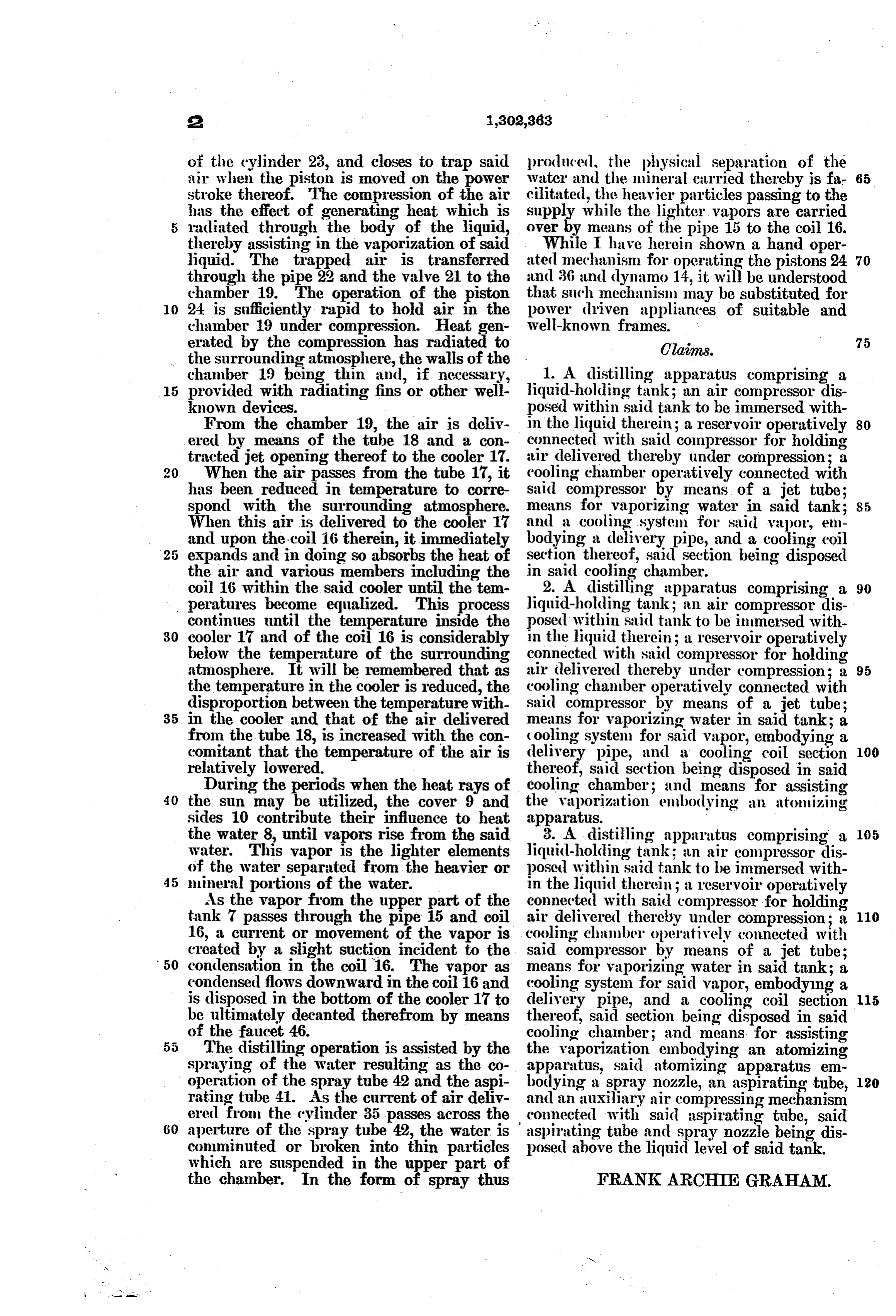
of the cylinder 23, and closes to trap said produced, the physical separation of the air when the piston is moved on the power Water and the mineral carried thereby is fa 65 stroke thereof. The compression of the air cilitated, the heavier particles passing to the has the effect of generating heat which is supply while the lighter vapors are carried radiated through the body of the liquid, over by means of the pipe 15 to the coil 16. thereby assisting in the vaporization of said While I have herein shown a hand oper liquid. The trapped air is transferred ated mechanism for operating the pistons 24 70 through the pipe 22 and the valve 21 to the and 36 and dynamo 14, it will be understood chamber 19. The operation of the piston that such mechanism may be substituted for O 24 is sufficiently rapid to hold air in the power driven appliances of suitable and chamber 19 under compression. Heat gen well-known frames.
erated by the compression has radiated to Claims. 75 the surrounding atmosphere, the walls of the chamber 19 being thin and, if necessary, 1. A distilling apparatus comprising a 5 provided with radiating fins or other well liquid-holding tank; an air compressor dis known devices. posed within said tank to be immersed with From the chamber 19, the air is deliv in the liquid therein; a reservoir operatively 80 ered by means of the tube 18 and a con connected with said compressor for holding tracted jet opening thereof to the cooler 17. air delivered thereby under compression; a When the air passes from the tube 17, it cooling chamber operatively connected with has been reduced in temperature to corre said compressor by means of a jet tube; spond with the surrounding atmosphere. means for vaporizing water in said tank; When this air is delivered to the cooler 17 and a cooling system for said vapor, em. and upon the coil 16 therein, it immediately bodying a delivery pipe, and a cooling coil expands and in doing so absorbs the heat of section thereof, said section being disposed the air and various members including the in said cooling chamber.
coil 16 within the said cooler until the tem 2. A distilling apparatus comprising a 90 peratures become equalized. This process liquid-holding tank; an air compressor dis continues until the temperature inside the posed within said tank to be immersed with 30 cooler 17 and of the coil 16 is considerably in the liquid therein; a reservoir operatively below the temperature of the surrounding connected with said compressor for holding atmosphere. It will be remembered that as air delivered thereby under compression; a 95 the temperature in the cooler is reduced, the cooling chamber operatively connected with disproportion between the temperature with said compressor by means of a jet tube; 35 in the cooler and that of the air delivered means for vaporizing water in said tank; a from the tube 18, is increased with the con cooling system for said vapor, embodying a comitant that the temperature of the air is delivery pipe, and a cooling coil section 00 relatively lowered. thereof, said section being disposed in said During the periods when the heat rays of cooling chamber; and means for assisting 40 the sun may be utilized, the cover 9 and the vaporization embodying an atomizing sides 10 contribute their influence to heat apparatus.
the water 8, until vapors rise from the said 8. A distilling apparatus comprising a 05 water. This vapor is the lighter elements liquid-holding tank; an air compressor dis of the water separated from the heavier or posed within said tank to be immersed with 45 mineral portions of the water. in the liquid therein; a reservoir operatively As the vapor from the upper part of the connected with said compressor for holding tank 7 passes through the pipe 15 and coil air delivered thereby under compression; a 10 16, a current or movement of the vapor is cooling chamber operatively connected with created by a slight suction incident to the said compressor by means of a jet tube; 50 condensation in the coil 16. The vapor as means for vaporizing water in said tank; a condensed flows downward in the coil 16 and cooling system for said vapor, embodying a is disposed in the bottom of the cooler 17 to delivery pipe, and a cooling coil section 5 be ultimately decanted therefrom by means thereof, said section being disposed in said of the faucet 46. cooling chamber; and means for assisting The distilling operation is assisted by the the vaporization embodying an atomizing spraying of the water resulting as the co apparatus, said atomizing apparatus em operation of the spray tube 42 and the aspi bodying a spray nozzle, an aspirating tube, 20 rating tube 41. As the current of air deliv and an auxiliary air compressing mechanism ered from the cylinder 35 passes across the connected with said aspirating tube, said 60 aperture of the spray tube 42, the water is aspirating tube and spray nozzle being dis conminuted or broken into thin particles posed above the liquid level of said tank. which are suspended in the upper part of the chamber. In the form of spray thus FRANKARCHIE GRAHAM.
Provenance
- Collection
- Cited prior art
- Original PDF
- patentimages.storage.googleapis.com →
- Filed
- 1918-09-14
- Pages
- 3
- Method
- pdftotext (the PDF's own text layer) + pdftoppm 300dpi page scans
- Source
- Google Patents bibliographic record
- Granted
- 1919-04-29
- Inventors
- Frank Archie Graham
- Transcribed from
- patentimages.storage.googleapis.com →