patent · US4020989
Light transmitting building panel
3 May 1977
Page 1 — bibliographic record
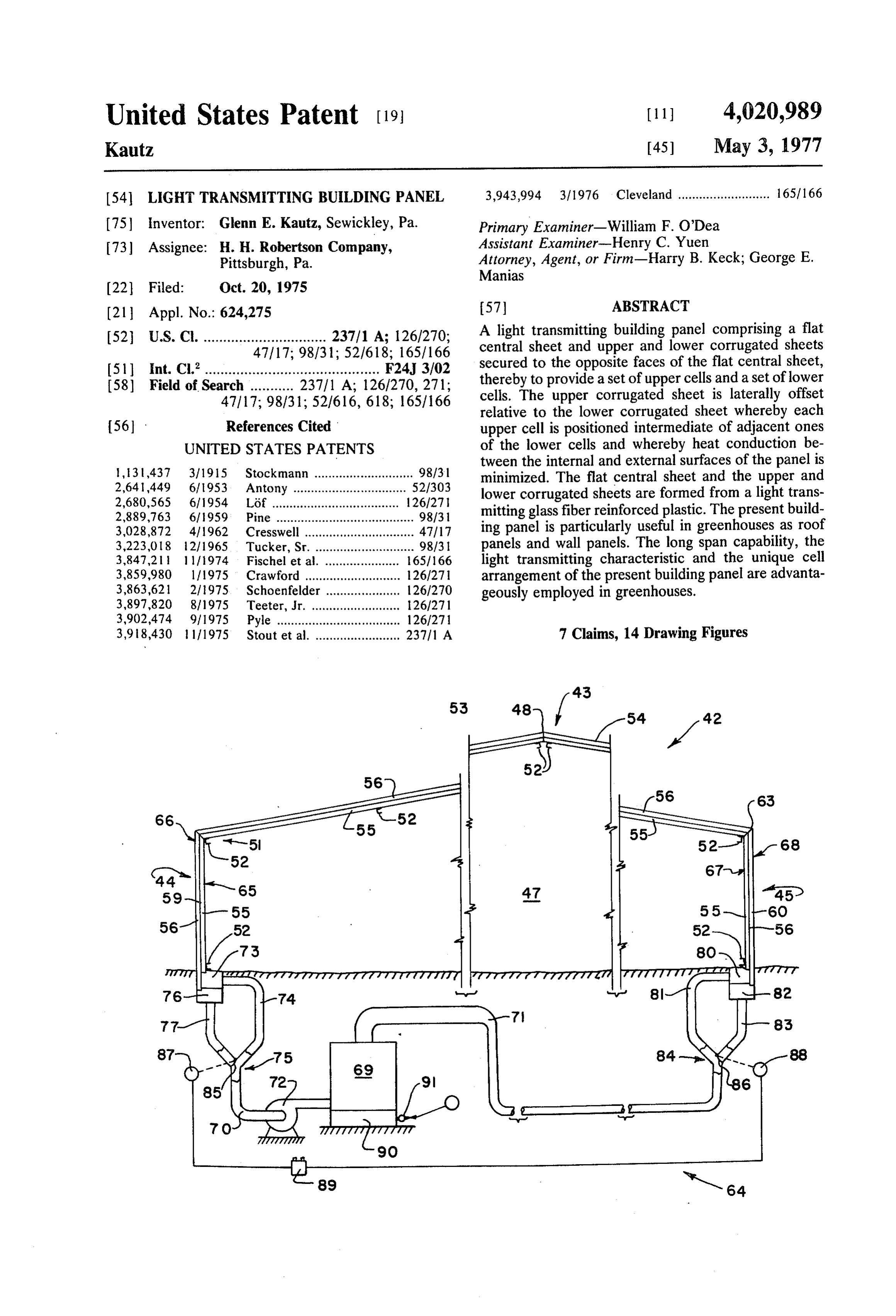
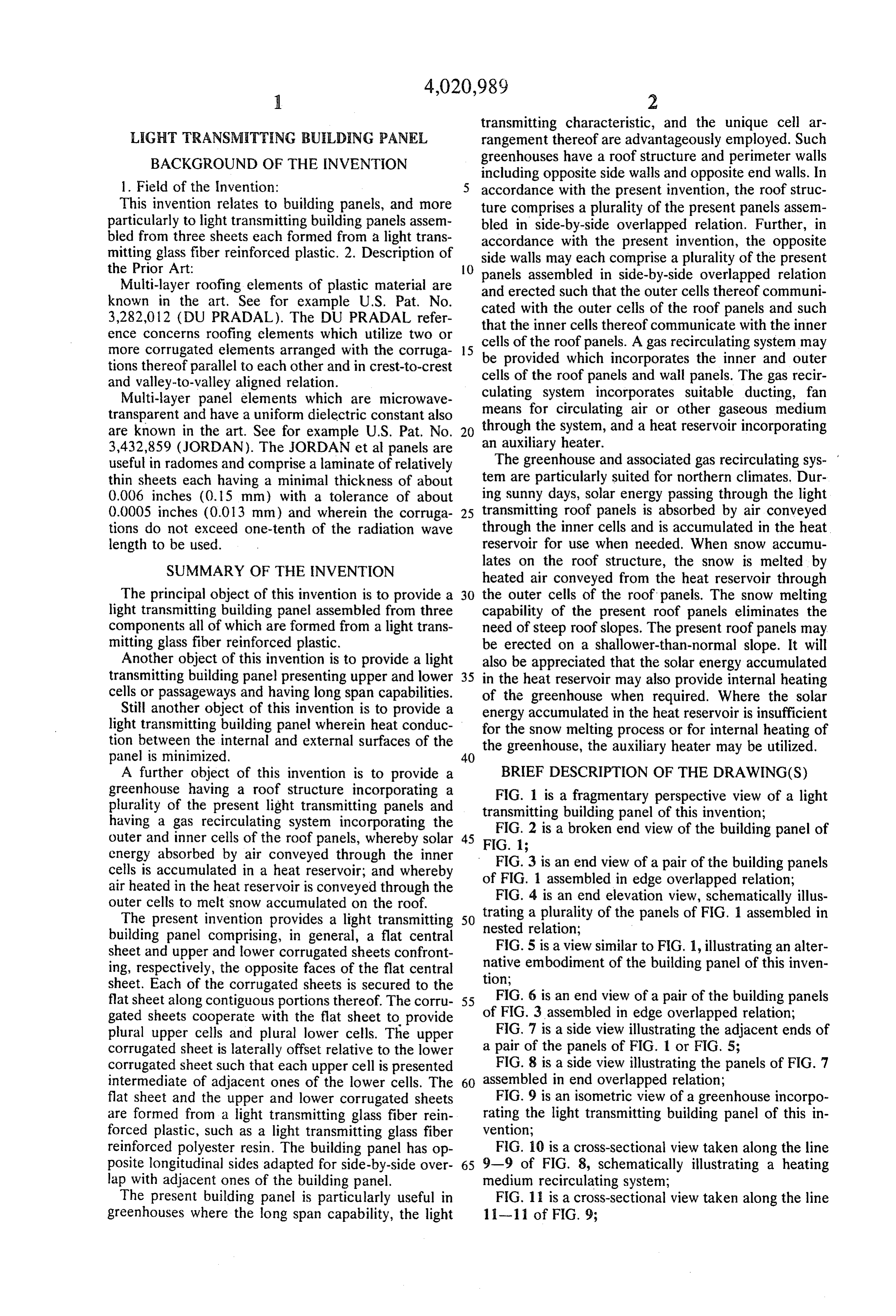
United States Patent (19) 11) 4,020,989 Kautz 45) May 3, 1977 (54) LIGHT TRANSMITTING BUILDING PANEL 3,943,994 3/1976 Cleveland .......................... 165/166 (75) inventor: Glenn E. Kautz, Sewickley, Pa. Primary Examiner-William F. O'Dea (73) Assignee: H. H. Robertson Company, Assistant Examiner-Henry C. Yuen Pittsburgh, Pa. Attorney, Agent, or Firm-Harry B. Keck; George E. Manias
(21 Appl. No.: 624,275 57 ABSTRACT 52 U.S. Cl. ............................... 237/1 A; 126/270; A light transmitting building panel comprising a flat 47/17; 98/31; 52/618; 165/166 central sheet and upper and lower corrugated sheets (51 int. Cl............................................. F24, 3/02 secured to the opposite faces of the flat central sheet, 58) Field of Search ........... 237/1 A; 126/270, 271; thereby to provide a set of upper cells and a set of lower 47/17; 98/31; 52/616, 618; 165/166 cells. The upper corrugated sheet is laterally offset relative to the lower corrugated sheet whereby each 56 References Cited upper cell is positioned intermediate of adjacent ones UNITED STATES PATENTs of the lower cells and whereby heat conduction be l, 3,437 3/1915 Stockmann ............................ 98/31 tween the internal and external surfaces of the panel is 2,641,449 6/1953 Antony ................................ 52/303 minimized. The flat central sheet and the upper and 2,680,565 6/1954 Löf .................................... 126/27 lower corrugated sheets are formed from a light trans 2,889,763 6/1959 Pine ....................................... 98/31 mitting glass fiber reinforced plastic. The present build 3.028,872 4/1962 Cresswell .................... ... 47/17 ing panel is particularly useful in greenhouses as roof 3.223,08 2/1965 Tucker, Sr............................. 98/31 panels and wall panels. The long span capability, the 3,847.2 l l l l (1974 Fischel et al. .................... 65/166 light transmitting characteristic and the unique cell 3,859,980 1/1975 Crawford ................... 126/27 arrangement of the present building panel are advanta 3,863,621 2/1975 Schoenfelder ..................... 126/270 geously employed in greenhouses.
3,902,474 9/1975 Pyle ................................. 126/27 3,918,430 1 1/1975 Stout et al......................... 23711 A 7 Claims, 14 Drawing Figures
Page 2
Drawing sheet — no readable text.
Page 3
Drawing sheet — no readable text.
Page 4
Drawing sheet — no readable text.
Page 5
transmitting characteristic, and the unique cell ar
LIGHT TRANSMETTING BUILDING PANEL rangement thereof are advantageously employed. Such BACKGROUND OF THE INVENTION greenhouses have a roof structure and perimeter walls including opposite side walls and opposite end walls. In 1. Field of the invention: 5 accordance with the present invention, the roof struc This invention relates to building panels, and more ture comprises a plurality of the present panels assem particularly to light transmitting building panels assem bled in side-by-side overlapped relation. Further, in bled from three sheets each formed from a light trans mitting glass fiber reinforced plastic. 2. Description of accordance side walls with the present invention, the opposite may each comprise a plurality of the present the Prior Art: 10 panels assembled in side-by-side overlapped relation Multi-layer roofing elements of plastic material are and erected such that the outer cells thereof communi known in the art. See for example U.S. Pat. No. cated with the outer cells of the roof panels and such 3,282,012 (DU PRADAL). The DU PRADAL refer that the inner cells thereof communicate with the inner ence concerns roofing elements which utilize two or cells of the roof panels. A gas recirculating system may more corrugated elements arranged with the corruga 15 be provided which incorporates the inner and outer tions thereof parallel to each other and in crest-to-crest cells of the roof panels and wall panels. The gas recir and valley-to-valley aligned relation. culating system incorporates suitable ducting, fan Multi-layer panel elements which are microwave means for circulating air or other gaseous medium transparent and have a uniform dielectric constant also are known in the art. See for example U.S. Pat. No. an auxiliary heater. a heat reservoir incorporating through the system, and 3,432,859 (JORDAN). The JORDAN et al panels are The greenhouse and associated gas recirculating sys useful in radomes and comprise a laminate of relatively thin sheets each having a minimal thickness of about tem are particularly suited for northern climates. Dur 0.006 inches (0.15 mm) with a tolerance of about ing sunny days, solar energy passing through the light 0.0005 inches (0.013 mm) and wherein the corruga 25 transmitting roof panels is absorbed by air conveyed tions do not exceed one-tenth of the radiation wave through the inner cells and is accumulated in the heat length to be used. reservoir for use when needed. When snow accumu SUMMARY OF THE INVENTION lates on the roof structure, the snow is melted by heated air conveyed from the heat reservoir through
The principal object of this invention is to provide a 30 the outer cells of the roof panels. The snow melting light transmitting building panel assembled from three capability of the present roof panels eliminates the components all of which are formed from a light trans need of steep roof slopes. The present roof panels may mitting glass fiber reinforced plastic. be erected on a shallower-than-normal slope. It will Another object of this invention is to provide a light also be appreciated that the solar energy accumulated transmitting building panel presenting upper and lower 35 in the heat reservoir may also provide internal heating cells or passageways and having long span capabilities. of the greenhouse when required. Where the solar Still another object of this invention is to provide a energy accumulated in the heat reservoir is insufficient light transmitting building panel wherein heat conduc for the snow melting process or for internal heating of tion between the internal and external surfaces of the the greenhouse, the auxiliary heater may be utilized.
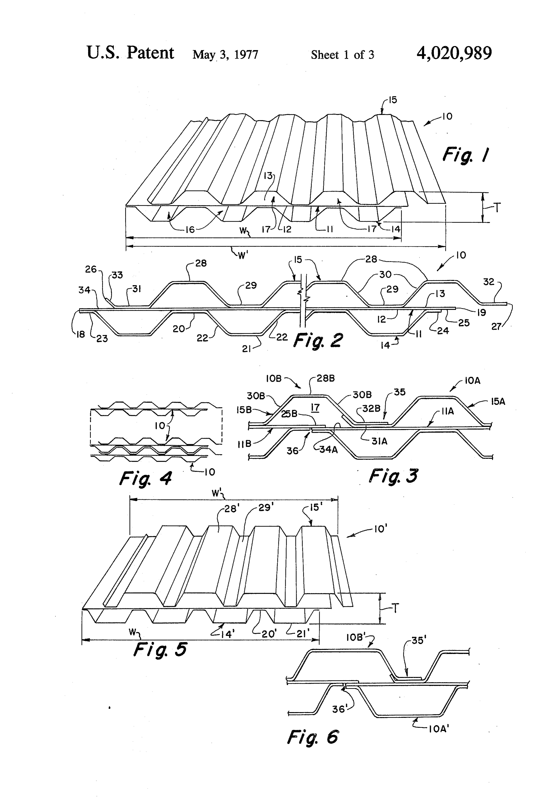
A further object of this invention is to provide a BRIEF DESCRIPTION OF THE DRAWING(S) greenhouse having a roof structure incorporating a FIG. 1 is a fragmentary perspective view of a light plurality of the present light transmitting panels and transmitting building panel of this invention; having a gas recirculating system incorporating the FIG. 2 is a broken end view of the building panel of outer and inner cells of the roof panels, whereby solar 45 FIG. 1;
energy absorbed by air conveyed through the inner cells is accumulated in a heat reservoir; and whereby ofFIG. FIG.
3 is an end view of a pair of the building panels 1 assembled in edge overlapped relation;
air heated in the heat reservoir is conveyed through the FIG. 4 is an end elevation view, schematically illus outer cells to melt snow accumulated on the roof.
The present invention provides a light transmitting 50 trating a plurality of the panels of FIG. 1 assembled in building panel comprising, in general, a flat central nested relation;
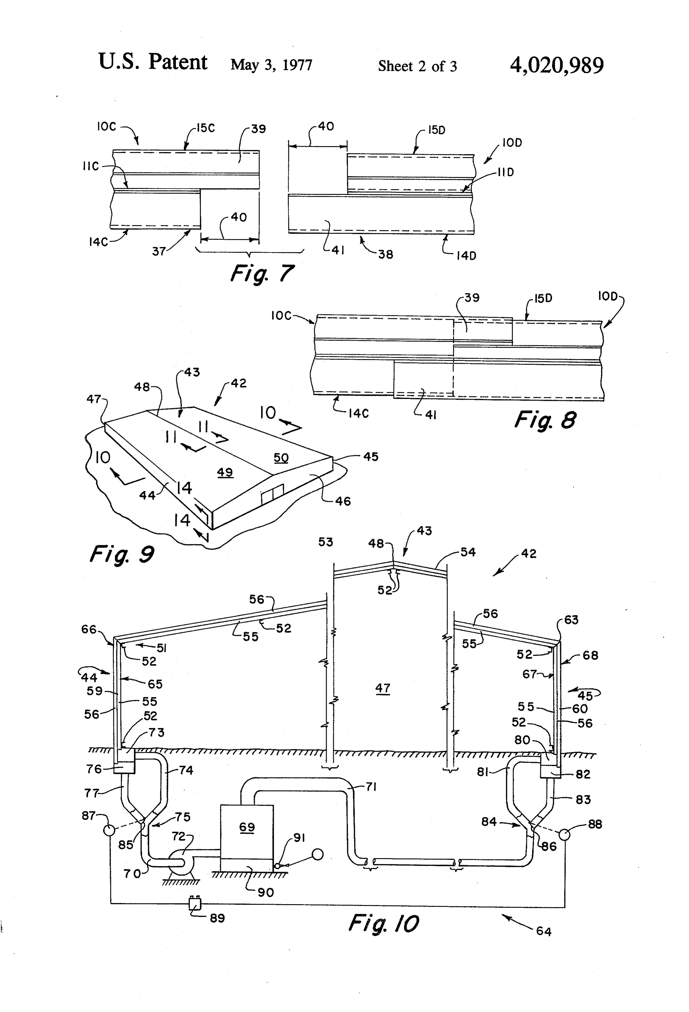
sheet and upper and lower corrugated sheets confront native FIG. 5 is a view similar to FIG. 1, illustrating an alter ing, respectively, the opposite faces of the flat central tion; embodiment of the building panel of this inven sheet. Each of the corrugated sheets is secured to the flat sheet along contiguous portions thereof. The corru 55 FIG. 6 is an end view of a pair of the building panels gated sheets cooperate with the flat sheet to provide ofFIG. FIG.3 assembled in edge overlapped relation; 7 is a side view illustrating the adjacent ends of plural upper cells and plural lower cells. The upper corrugated sheet is laterally offset relative to the lower a pair of the panels of FIG. 1 or FIG. 5; corrugated sheet such that each upper cell is presented FIG. 8 is a side view illustrating the panels of FIG. 7 intermediate of adjacent ones of the lower cells. The 60 assembled in end overlapped relation; flat sheet and the upper and lower corrugated sheets FIG. 9 is an isometric view of a greenhouse incorpo are formed from a light transmitting glass fiber rein rating the light transmitting building panel of this in forced plastic, such as a light transmitting glass fiber vention;
reinforced polyester resin. The building panel has op FIG. 10 is a cross-sectional view taken along the line posite longitudinal sides adapted for side-by-side over 65 9-9 of FIG. 8, schematically illustrating a heating lap with adjacent ones of the building panel. medium recirculating system;
The present building panel is particularly useful in FIG. 11 is a cross-sectional view taken along the line greenhouses where the long span capability, the light 11-11 of FIG. 9;
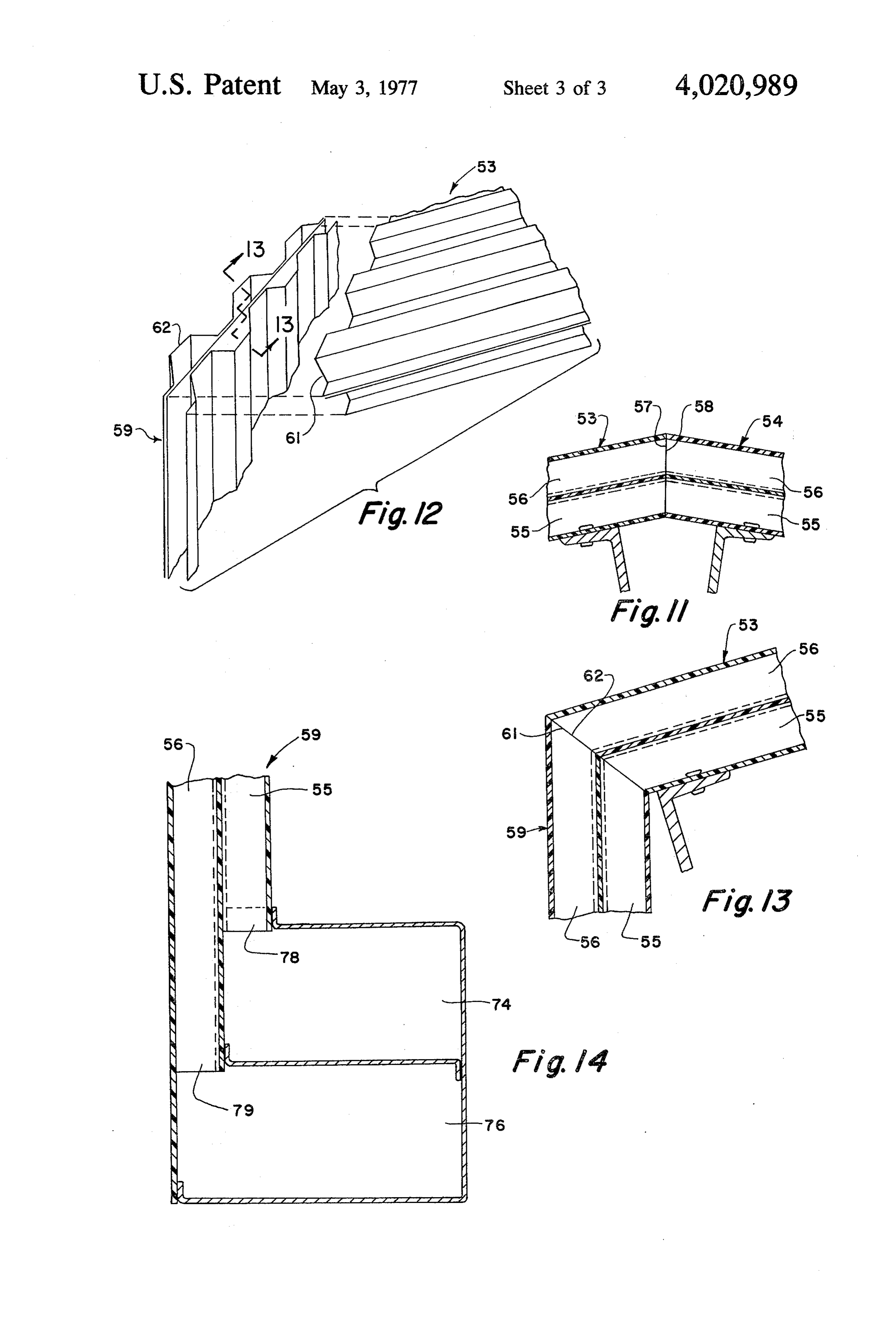
Page 6
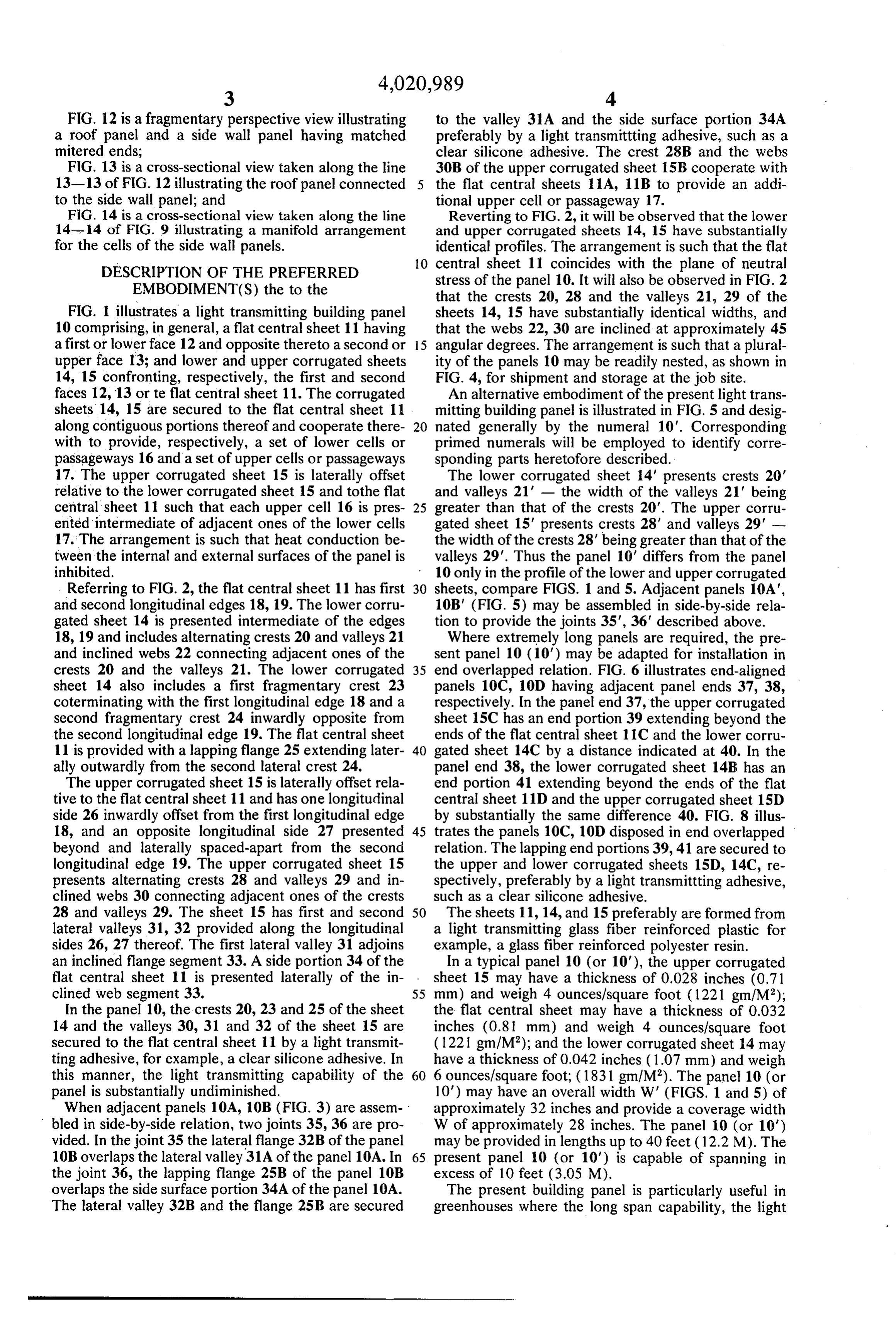
FIG. 12 is a fragmentary perspective view illustrating to the valley 31A and the side surface portion 34A a roof panel and a side wall panel having matched preferably by a light transmittting adhesive, such as a mitered ends; clear silicone adhesive. The crest 28B and the webs FIG. 13 is a cross-sectional view taken along the line 30B of the upper corrugated sheet 15B cooperate with 13-13 of FIG. 12 illustrating the roof panel connected the flat central sheets 11A, 11B to provide an addi to the side wall panel; and tional upper cell or passageway 17. F.G. 14 is a cross-sectional view taken along the line Reverting to FIG. 2, it will be observed that the lower 14-14 of FIG. 9 illustrating a manifold arrangement and upper corrugated sheets 14, 15 have substantially for the cells of the side wall panels. identical profiles. The arrangement is such that the flat O central sheet 11 coincides with the plane of neutral
DESCRIPTION OF THE PREFERRED stress of the panel 10. It will also be observed in FIG. 2 EMBODIMENT(S) the to the that the crests 20, 28 and the valleys 21, 29 of the FIG. 1 illustrates a light transmitting building panel sheets 14, 15 have substantially identical widths, and 10 comprising, in general, a flat central sheet 11 having that the webs 22, 30 are inclined at approximately 45 a first or lowerface 12 and opposite thereto a second or 5 angular degrees. The arrangement is such that a plural upper face 13; and lower and upper corrugated sheets ity of the panels 10 may be readily nested, as shown in 14, 15 confronting, respectively, the first and second FIG. 4, for shipment and storage at the job site. faces 12, 13 or te flat central sheet 11. The corrugated An alternative embodiment of the present light trans sheets 14, 15 are secured to the flat central sheet 11 mitting building panel is illustrated in FIG. 5 and desig along contiguous portions thereof and cooperate there 20 nated generally by the numeral 10'. Corresponding with to provide, respectively, a set of lower cells or primed numerals will be employed to identify corre passageways 16 and a set of upper cells or passageways sponding parts heretofore described. 17. The upper corrugated sheet 15 is laterally offset The lower corrugated sheet 14' presents crests 20' relative to the lower corrugated sheet 15 and tothe flat and valleys 21' - the width of the valleys 21" being central sheet 11 such that each upper cell 16 is pres 25 greater than that of the crests 20'. The upper corru ented intermediate of adjacent ones of the lower cells gated sheet 15' presents crests 28' and valleys 29' - 17. The arrangement is such that heat conduction be the width of the crests 28' being greater than that of the tween the internal and external surfaces of the panel is valleys 29'. Thus the panel 10' differs from the panel inhibited. 10 only in the profile of the lower and upper corrugated Referring to FIG. 2, the flat central sheet 11 has first 30 sheets, compare FIGS. 1 and 5. Adjacent panels 10A", and second longitudinal edges 18, 19. The lower corru 10B' (FIG. 5) may be assembled in side-by-side rela gated sheet 14 is presented intermediate of the edges tion to provide the joints 35', 36' described above. 18, 19 and includes alternating crests 20 and valleys 21 Where extremely long panels are required, the pre and inclined webs 22 connecting adjacent ones of the sent panel 10 (10') may be adapted for installation in crests 20 and the valleys 21. The lower corrugated 35 end overlapped relation. FIG. 6 illustrates end-aligned sheet 14 also includes a first fragmentary crest 23 panels 10C, 10D having adjacent panel ends 37, 38, coterminating with the first longitudinal edge 18 and a respectively. In the panel end 37, the upper corrugated second fragmentary crest 24 inwardly opposite from sheet 15C has an end portion 39 extending beyond the the second longitudinal edge 19. The flat central sheet ends of the flat central sheet 11C and the lower corru 11 is provided with a lapping flange 25 extending later 40 gated sheet 14C by a distance indicated at 40. In the ally outwardly from the second lateral crest 24. panel end 38, the lower corrugated sheet 14B has an The upper corrugated sheet 15 is laterally offset rela end portion 41 extending beyond the ends of the flat tive to the flat central sheet 11 and has one longitudinal central sheet 11D and the upper corrugated sheet 15D side 26 inwardly offset from the first longitudinal edge by substantially the same difference 40. FIG. 8 illus 18, and an opposite longitudinal side 27 presented 45 trates the panels 10C, 10D disposed in end overlapped beyond and laterally spaced-apart from the second relation. The lapping end portions 39, 41 are secured to longitudinal edge 19. The upper corrugated sheet 15 the upper and lower corrugated sheets 15D, 14C, re presents alternating crests 28 and valleys 29 and in spectively, preferably by a light transmittting adhesive, clined webs 30 connecting adjacent ones of the crests such as a clear silicone adhesive.
28 and valleys 29. The sheet 15 has first and second 50 The sheets 11, 14, and 15 preferably are formed from lateral valleys 31, 32 provided along the longitudinal a light transmitting glass fiber reinforced plastic for sides 26, 27 thereof. The first lateral valley 31 adjoins example, a glass fiber reinforced polyester resin. an inclined flange segment 33. A side portion 34 of the In a typical panel 10 (or 10'), the upper corrugated flat central sheet 11 is presented laterally of the in sheet 15 may have a thickness of 0.028 inches (0.71 clined web segment 33. 55 mm) and weigh 4 ounces/square foot (1221 gm/M); In the panel 10, the crests 20, 23 and 25 of the sheet the flat central sheet may have a thickness of 0.032 14 and the valleys 30, 31 and 32 of the sheet 15 are inches (0.81 mm) and weigh 4 ounces/square foot secured to the flat central sheet 11 by a light transmit (1221 gm/M); and the lower corrugated sheet 14 may ting adhesive, for example, a clear silicone adhesive. In have a thickness of 0.042 inches (1.07 mm) and weigh this manner, the light transmitting capability of the 60 6 ounces/square foot; (1831 gm/M). The panel 10 (or panel is substantially undiminished. 10') may have an overall width W' (FIGS. 1 and 5) of When adjacent panels 10A, 10B (FIG. 3) are assem approximately 32 inches and provide a coverage width bled in side-by-side relation, two joints 35, 36 are pro W of approximately 28 inches. The panel 10 (or 10') vided. In the joint 35 the lateral flange 32B of the panel may be provided in lengths up to 40 feet (12.2 M). The 10B overlaps the lateral valley 31A of the panel 10A. In 65 present panel 10 (or 10') is capable of spanning in the joint 36, the lapping flange 25B of the panel 10B excess of 10 feet (3.05 M).
overlaps the side surface portion 34A of the panel 10A. The present building panel is particularly useful in The lateral valley 32B and the flange 25B are secured greenhouses where the long span capability, the light
Page 7
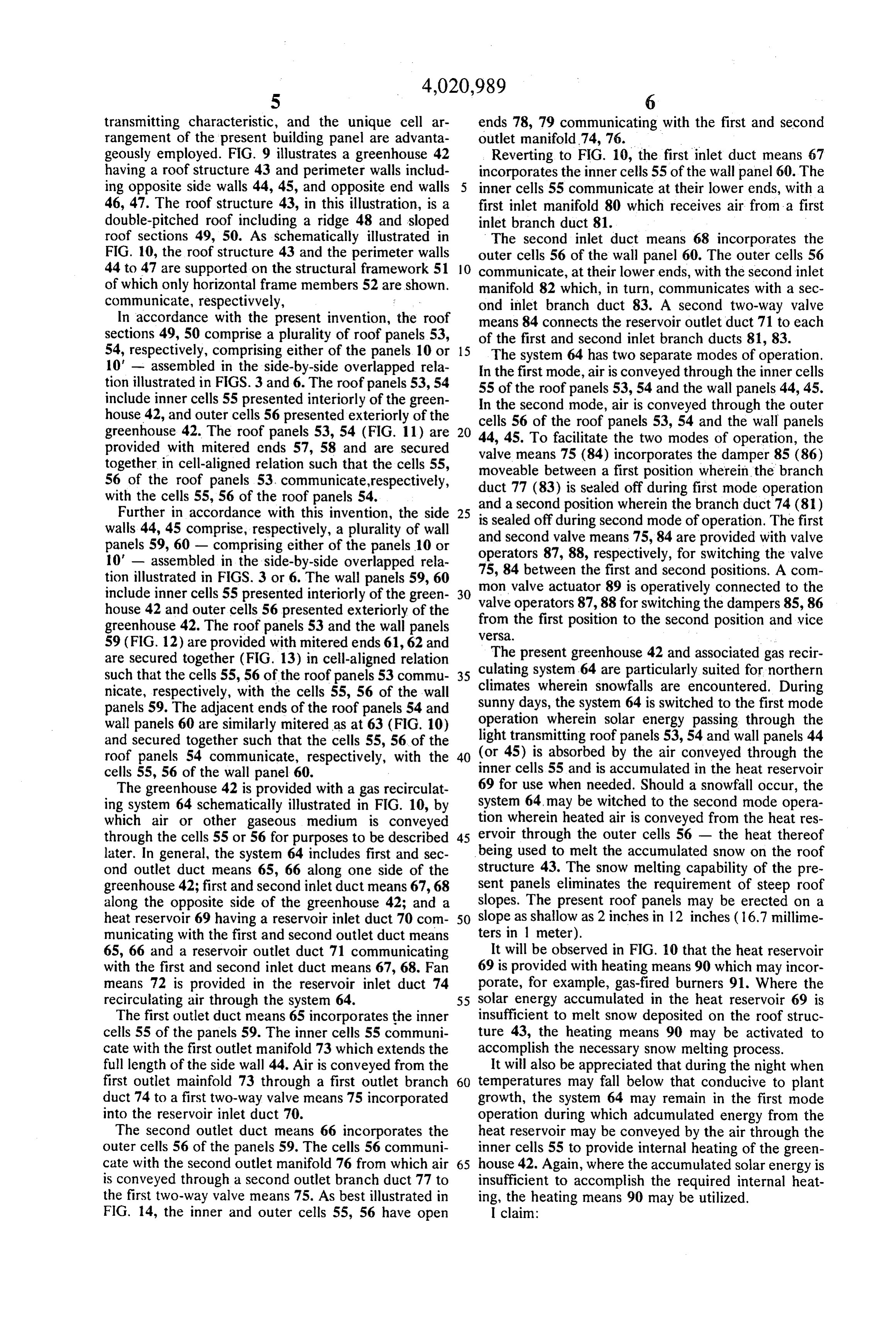
transmitting characteristic, and the unique cell ar ends 78, 79 communicating with the first and second rangement of the present building panel are advanta outlet manifold 74,76.
geously employed. FIG. 9 illustrates a greenhouse 42 Reverting to FIG. 10, the first inlet duct means 67 having a roof structure 43 and perimeter walls includ incorporates the inner cells 55 of the wall panel 60. The ing opposite side walls 44, 45, and opposite end walls inner cells 55 communicate at their lower ends, with a 46, 47. The roof structure 43, in this illustration, is a first inlet manifold 80 which receives air from a first double-pitched roof including a ridge 48 and sloped inlet branch duct 81.
roof sections 49, 50. As schematically illustrated in The second inlet duct means 68 incorporates the FIG. 10, the roof structure 43 and the perimeter walls outer cells 56 of the wall panel 60. The outer cells 56 44 to 47 are supported on the structural framework 51 communicate, at their lower ends, with the second inlet
of which only horizontal frame members 52 are shown. manifold 82 which, in turn, communicates with a sec communicate, respectivvely, ond inlet branch duct 83. A second two-way valve In accordance with the present invention, the roof means 84 connects the reservoir outlet duct 71 to each sections 49, 50 comprise a plurality of roof panels 53, of the first and second inlet branch ducts 81, 83. 54, respectively, comprising either of the panels 10 or 15 The system 64 has two separate modes of operation. 10' - assembled in the side-by-side overlapped rela In the first mode, air is conveyed through the inner cells tion illustrated in FIGS. 3 and 6. The roof panels 53, 54 55 of the roof panels 53, 54 and the wall panels 44, 45. include inner cells 55 presented interiorly of the green In the second mode, air is conveyed through the outer house 42, and outer cells 56 presented exteriorly of the cells 56 of the roof panels 53, 54 and the wall panels greenhouse 42. The roof panels 53, 54 (FIG. 11) are 20 44, provided with mitered ends 57, 58 and are secured valve45.means To facilitate the two modes of operation, the 75 (84) incorporates the damper 85 (86) together in cell-aligned relation such that the cells 55, moveable between a first position wherein the branch 56 of the roof panels 53, communicate, respectively, duct 77 (83) is sealed off during first mode operation with the cells 55, 56 of the roof panels 54.
Further in accordance with this invention, the side 25 is sealed off during second modetheofbranch and a second position wherein duct 74 (81) operation. The first walls 44, 45 comprise, respectively, a plurality of wall and second valve means 75, 84 are provided with valve panels 59, 60 - comprising either of the panels 10 or operators 87, 88, respectively, for switching the valve 10' - assembled in the side-by-side overlapped rela tion illustrated in FIGS. 3 or 6. The wall panels 59, 60 75, 84 between the first and second positions. A com include inner cells 55 presented interiorly of the green 30 valvevalve mon actuator 89 is operatively connected to the operators 87,88 for switching the dampers 85,86 house 42 and outer cells 56 presented exteriorly of the from greenhouse 42. The roof panels 53 and the wall panels WeSa.the first position to the second position and vice 59 (FIG. 12) are provided with mitered ends 61, 62 and The present greenhouse 42 and associated gas recir are secured together (FIG. 13) in cell-aligned relation culating such that the cells 55, 56 of the roof panels 53 commu climates system 35 64 are particularly suited for northern wherein snowfalls are encountered. During nicate, respectively, with the cells 55, 56 of the wall sunny days, the system 64 is switched to the first mode panels 59. The adjacent ends of the roof panels 54 and operation wherein solar energy passing through the wall panels 60 are similarly mitered as at 63 (FIG. 10) light transmitting roof and secured together such that the cells 55, 56 of the (or 45) is absorbed bypanels 53, 54 and wall panels 44 the air conveyed through the roof panels 54 communicate, respectively, with the 40 inner cells 55 and is accumulated in the heat reservoir cells 55, 56 of the wall panel 60.
The greenhouse 42 is provided with a gas recirculat 69 for use when needed. Should a snowfall occur, the ing system 64 schematically illustrated in FIG. 10, by system 64, may be witched to the second mode opera which air or other gaseous medium is conveyed tion wherein heated air is conveyed from the heat res through the cells 55 or 56 for purposes to be described 45 ervoir through the outer cells 56 - the heat thereof later. In general, the system 64 includes first and sec being used to melt the accumulated snow on the roof ond outlet duct means 65, 66 along one side of the structure 43. The snow melting capability of the pre greenhouse 42; first and second inlet duct means 67,68 sent panels eliminates the requirement of steep roof along the opposite side of the greenhouse 42; and a slopes. The present roof panels may be erected on a heat reservoir 69 having a reservoir inlet duct 70 com 50 slope as shallow as 2 inches in 12 inches (16.7 millime municating with the first and second outlet duct means ters in 1 meter).
65, 66 and a reservoir outlet duct 71 communicating It will be observed in FIG. 10 that the heat reservoir with the first and second inlet duct means 67, 68. Fan 69 is provided with heating means 90 which may incor means 72 is provided in the reservoir inlet duct 74 porate, for example, gas-fired burners 91. Where the recirculating air through the system 64. 55 solar energy accumulated in the heat reservoir 69 is The first outlet duct means 65 incorporates the inner insufficient to melt snow deposited on the roof struc cells 55 of the panels 59. The inner cells 55 communi ture 43, the heating means 90 may be activated to cate with the first outlet manifold 73 which extends the accomplish the necessary snow melting process. full length of the side wall 44. Air is conveyed from the It will also be appreciated that during the night when first outlet mainfold 73 through a first outlet branch 60 temperatures may fall below that conducive to plant duct 74 to a first two-way valve means 75 incorporated growth, the system 64 may remain in the first mode into the reservoir inlet duct 70. operation during which adcumulated energy from the The second outlet duct means 66 incorporates the heat reservoir may be conveyed by the air through the outer cells 56 of the panels 59. The cells 56 communi inner cells 55 to provide internal heating of the green cate with the second outlet manifold 76 from which air 65 house 42. Again, where the accumulated solar energy is is conveyed through a second outlet branch duct 77 to insufficient to accomplish the required internal heat the first two-way valve means 75. As best illustrated in ing, the heating means 90 may be utilized. FIG. 14, the inner and outer cells 55, 56 have open I claim:
Page 8
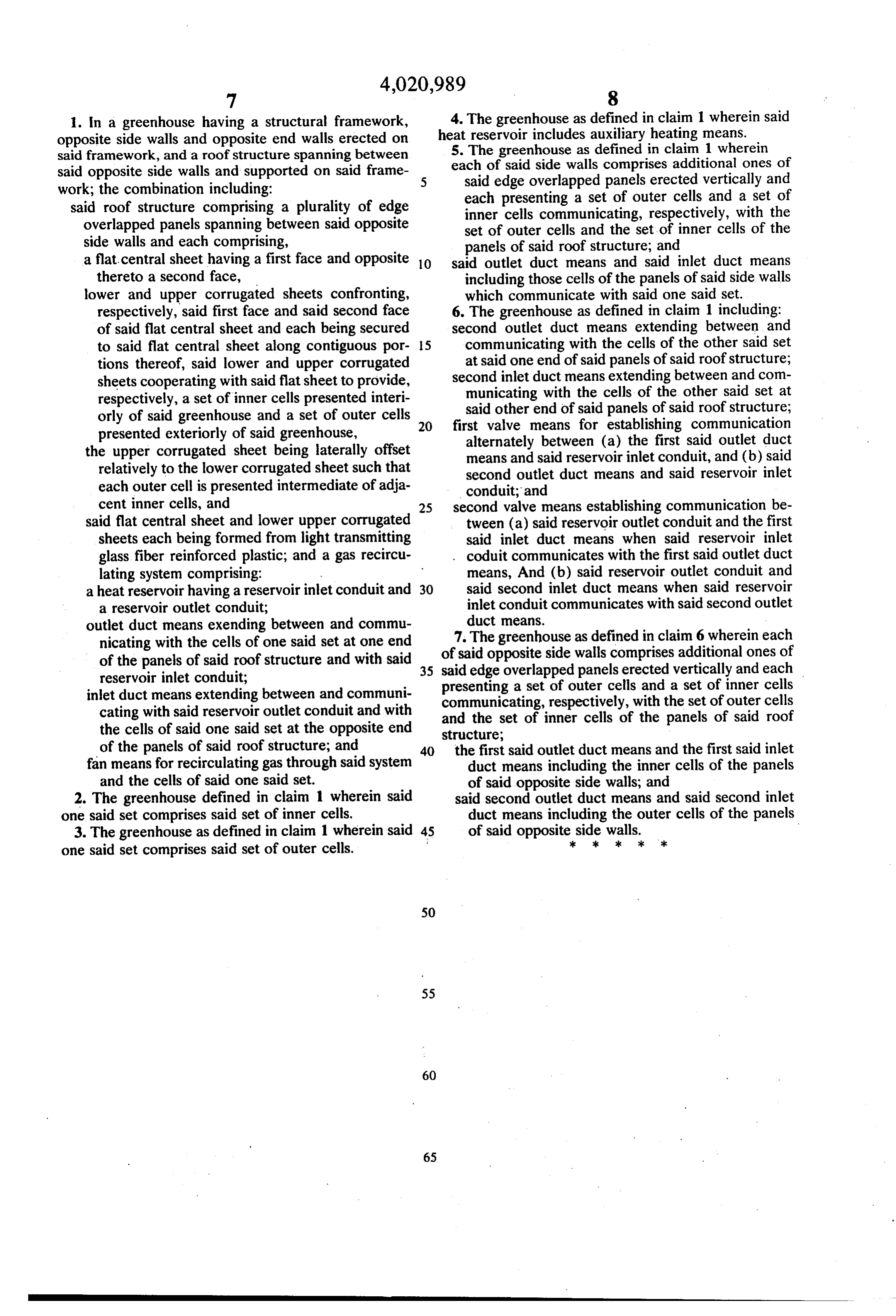
1. In a greenhouse having a structural framework, 4. The greenhouse as defined in claim 1 wherein said opposite side walls and opposite end walls erected on heat reservoir includes auxiliary heating means. 5. The greenhouse as defined in claim 1 wherein said framework, and a roof structure spanning between said opposite side walls and supported on said frame 5 each said of said side walls comprises additional ones of edge overlapped panels erected vertically and work; the combination including: each presenting a set of outer cells and a set of said roof structure comprising a plurality of edge inner cells communicating, respectively, with the overlapped panels spanning between said opposite set of outer cells and the set of inner cells of the side walls and each comprising, panels of said roof structure; and a flat central sheet having a first face and opposite 10 said outlet duct means and said inlet duct means thereto a second face, including those cells of the panels of said side walls lower and upper corrugated sheets confronting, which communicate with said one said set. respectively, said first face and said second face 6. The greenhouse as defined in claim 1 including: of said flat central sheet and each being secured second outlet duct means extending between and to said flat central sheet along contiguous por 5 communicating with the cells of the other said set tions thereof, said lower and upper corrugated at said one end of said panels of said roof structure; sheets cooperating with said flat sheet to provide, second inlet duct means extending between and com respectively, a set of inner cells presented interi municating with the cells of the other said set at orly of said greenhouse and a set of outer cells 20 first said other end of said panels of said roof structure; presented exteriorly of said greenhouse, valve means for establishing communication the upper corrugated sheet being laterally offset alternately between (a) the first said outlet duct means and said reservoir inlet conduit, and (b) said relatively to the lower corrugated sheet such that second outlet duct means and said reservoir inlet each outer cell is presented intermediate of adja conduit; and cent inner cells, and 25 second valve means establishing communication be said flat central sheet and lower upper corrugated tween (a) said reservoir outlet conduit and the first sheets each being formed from light transmitting said inlet duct means when said reservoir inlet glass fiber reinforced plastic; and a gas recircu coduit communicates with the first said outlet duct lating system comprising: means, And (b) said reservoir outlet conduit and a heat reservoir having a reservoir inlet conduit and 30 said second inlet duct means when said reservoir inlet conduit communicates with said second outlet a reservoir outlet conduit;
outlet duct means exending between and commu duct means.
nicating with the cells of one said set at one end of7.saidThe greenhouse as defined in claim 6 wherein each opposite side walls comprises additional ones of of the panels of said roof structure and with said 35 said edge overlapped panels erected vertically and each reservoir inlet conduit; presenting a set of outer cells and a set of inner cells inlet duct means extending between and communi communicating, respectively, with the set of outer cells cating with said reservoir outlet conduit and with and the set of inner cells of the panels of said roof the cells of said one said set at the opposite end structure;
of the panels of said roof structure; and 40 the first said outlet duct means and the first said inlet fan means for recirculating gas through said system duct means including the inner cells of the panels and the cells of said one said set. of said opposite side walls; and 2. The greenhouse defined in claim 1 wherein said said second outlet duct means and said second inlet one said set comprises said set of inner cells, duct means including the outer cells of the panels 3. The greenhouse as defined in claim 1 wherein said 45 of said oppositeXksideis walls.
one said set comprises said set of outer cells.
Provenance
- Collection
- Cited prior art
- Original PDF
- patentimages.storage.googleapis.com →
- Filed
- 1975-10-20
- Pages
- 8
- Method
- pdftotext (the PDF's own text layer) + pdftoppm 300dpi page scans
- Source
- Google Patents bibliographic record
- Granted
- 1977-05-03
- Inventors
- Glenn E. Kautz; HH Robertson Co
- Transcribed from
- patentimages.storage.googleapis.com →