patent · US3868211
Pollutant reduction with selective gas stack recirculation
25 February 1975
Page 1
United States Patent 01
Haye et al.
[54] POLLUTANT REDUCTION WITH
SELECTIVE GAS STACK RECIRCULATION
{76] Inventors: Paul G. La Haye; John W. Bjerklie, both of Cape Elizabeth, Maine;
Aqua-Chem, Inc., Milwaukee,
Wis.
[SL] Int. Chics sceeeneersecseereeeneeeeees F231 9/00
[56] References Cited
UNITED STATES PATENTS
Primary Examiner—Edward G. Favors
Attorney, Agent, or Firm—Fred Wiviott; Ralph G. Hohenfeldt
[57] ABSTRACT
A flame is produced in a combustion chamber with a burner supplied with fuel and less than the amount of air for complete combustion. The remainder of the air required for complete combustion is injected separately. Stack gas containing substantial carbon dioxide is mixed selectively with the gaseous combustion products. By well known reactions the carbon dioxide reacts with carbon in the combustion products to produce carbon monoxide which is later oxidized to carbon dioxide under conditions which do not promote production of noxious nitrogen oxides. The principles of the invention are applicable to a variety of fuel burners.
33 Claims, 6 Drawing Figures
Page 2
Drawing sheet — no readable text.
Page 3
pon f—~ TO AIR SUPPLY
NOTIN N
qIN ON RONSOg Wawae
SSAAASAY
Ni A_VZ, CPM MMM A
—_ , WARSI
a3 W&ss GAS
PATENTED FEB2 51875
Page 4
| VNN XN TN = J
SISSY EEE AIS
Sy SAYS
TRSTTT ANNI SN NY
NN NAN We
SSS a
SJ RECIRCULATED
STACK GASES
SONODASITNNW- 3WIL ONINYNE
CARBON PARTICLE SIZE MICRONS
SHEET 3
PATENTED FEB2 51975
Page 5
POLLUTANT REDUCTION WITH SELECTIVE GAS
STACK RECIRCULATION
BACKGROUND OF THE INVENTION
This invention relates to a method and apparatus for reducing air pollution agents such as nitrogen oxide, carbon monoxide, carbonaceous particulates and unburned hydrocarbons in the exhaust or stack gases or carbonaceous and hydrocarbon fuel burners.
A recently made important improvement in reducing the aforementioned pollutants is characterized as radially staged combustion which involves injecting fuel into a combustion chamber with less than the amount of air required for stoichiometric combustion so that burning takes place in a flame core which has a relatively small diameter near the burner and expands outwardly as it is propagated down the combustion chamber. Because the core mixture is rich in fuel, combustion is very incomplete near the burner and the gaseous core is much cooler than it would be if all the air for complete combustion were injected in the fuel. The cooler temperatures and rich fuel content of the core tends to inhibit formation of nitrogen oxides. This results in part from the oxygen in the air combining preferentially with the constituents of the fuel instead of with nitrogen under low temperature fuel-rich conditions. A sheath of air is also injected so as to surround and swirl around the core with little mixing near the burner. After some heat is extracted from the core as it progresses down the combustion chamber, mixing of the core gases and sheath air becomes more complete and the unburned constituents are oxidized in this stage under relatively low temperature conditions again so as to inhibit nitrogen oxide production. In some forms of this apparatus, further mixing turbulence is promoted by a grid interposed in the flame path remote from the burner. Some of the combustion air may also be injected through, the grid to increase velocity and promote turbulence which encourages oxidation of the combustible constituents without significant production of nitrogen oxides since intimate mixing rather than high temperature is relied upon to complete oxidation.
The arrangement just discussed is effective in reducing unburned solids such as carbon and nitrogen oxide. However, in some combustion systems used in boilers, particularly, when certain types of fuels are used, the stack gases have a higher than desired amount of carbon manifested as smoke. Thus, the present invention is concerned with reducing smoke as well as nitrogen oxides and other pollutants in the stack gases by a method which is applicable to the above described staged combustion technique and other fuel burning techniques as well by the selective recirculation of stack gas.
SUMMARY OF THE INVENTION
In accordance with the invention, some of the air for combustion which is injected into the combustion chamber in various streams is mixed with or supplanted by gaseous combustion products taken from the stack or flue and recirculated through the combustion chamber. In or beyond the combustion chamber downstream from the burner, carbon dioxide from the stack gas is caused to react with the carbon particles in the gaseous combustion products to produce carbon monoxide which is further oxidized to carbon dioxide in latter
stages of the combustion process. In this manner, the carbon which would otherwise result in visible smoke emitting from the stack is oxidized completely. The net result is that use of recirculated stack gas achieves smoke control at closer to ideal or stoichiometric. air than can be achieved with air alone.
A general object of this invention is to provide a combustion method and apparatus wherein nitrogen oxides, carbon monoxide, gaseous and particulate hydrocarbons and carbon in the exhaust or stack gas are substantially reduced as compared with conventional methods wherein all of the combustion supporting gases are introduced intimately with the fuel.
Another object is to react carbon dioxide from the exhaust gases with carbon resulting from incomplete combustion and to react the resulting combustion products with oxygen from air to reduce carbon and carbon monoxide in the exhaust gases.
A further object of this invention is to provide a combustion method and apparatus for minimizing the aforementioned atmospheric pollutants without adversely affecting the efficiency of the combustion process by selectively recirculating the stack gases and thereby reducing to a minimum the amount that must be recirculated to accomplish a given result.
Another object of this invention is to minimize in the exhaust gases from a fuel burner the particulate carbon content which appears as smoke and yet maintain satisfactorily low levels of nitrogen oxides in the stack gases. .
How the foregoing and other more specific objects of the invention are achieved will appear in the ensuing more detailed description of embodiments of the invention taken in conjunction with the drawings.
DESCRIPTION OF THE DRAWINGS
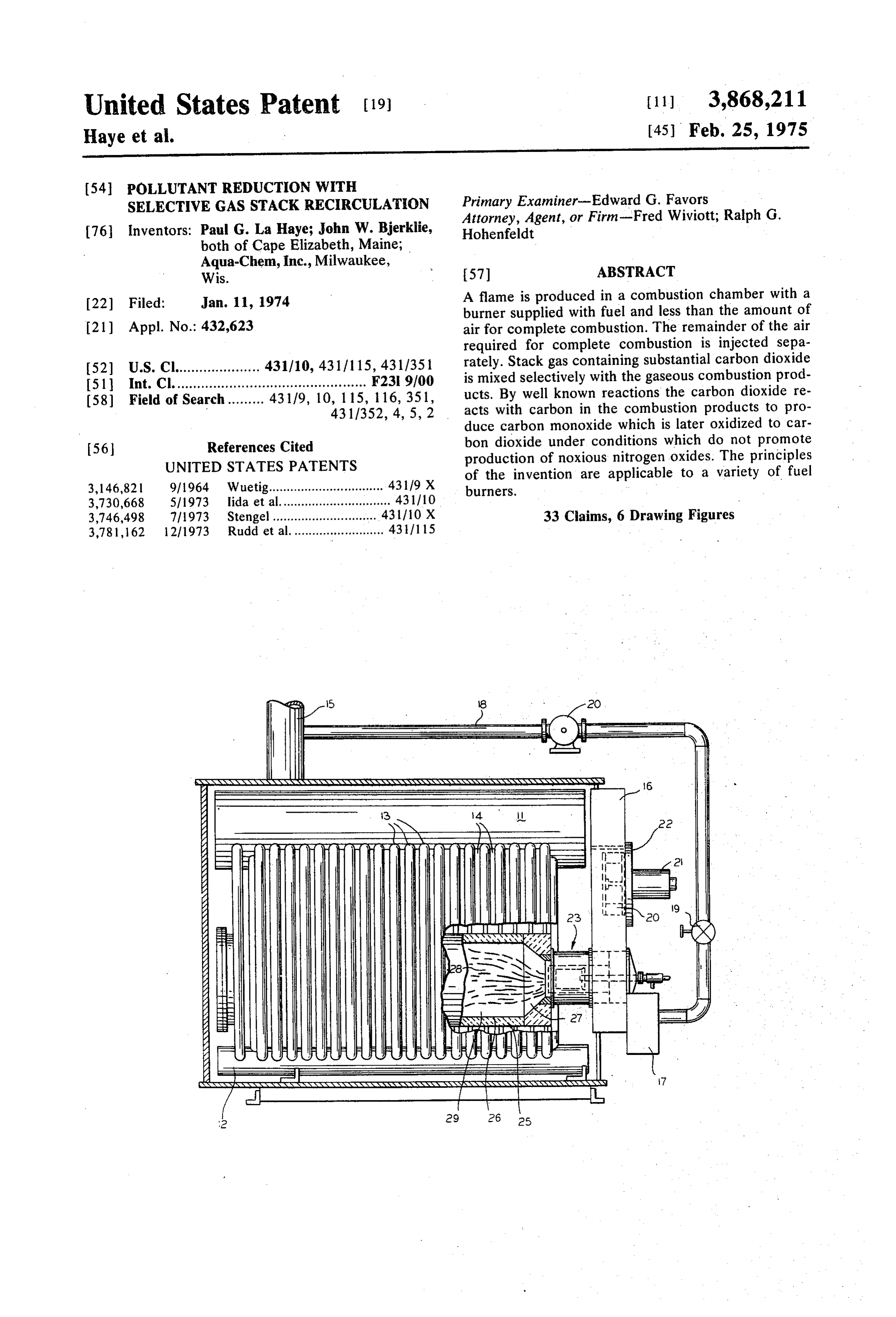
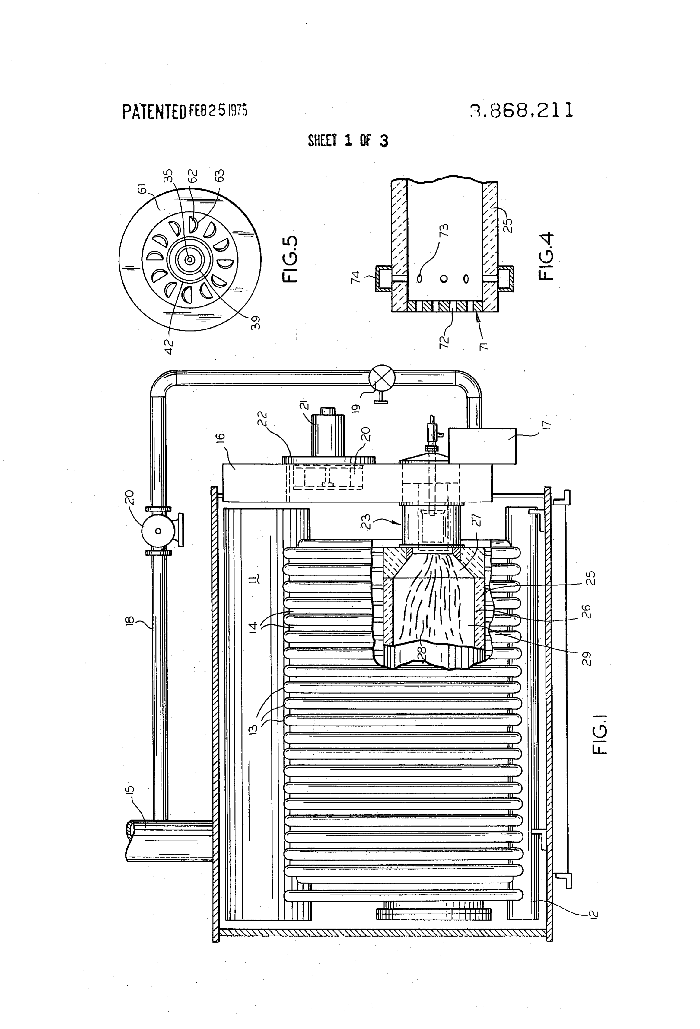
FIG. 1 shows a boiler with parts broken away to illustrate a combustion device in which the principles of the invention are used; :
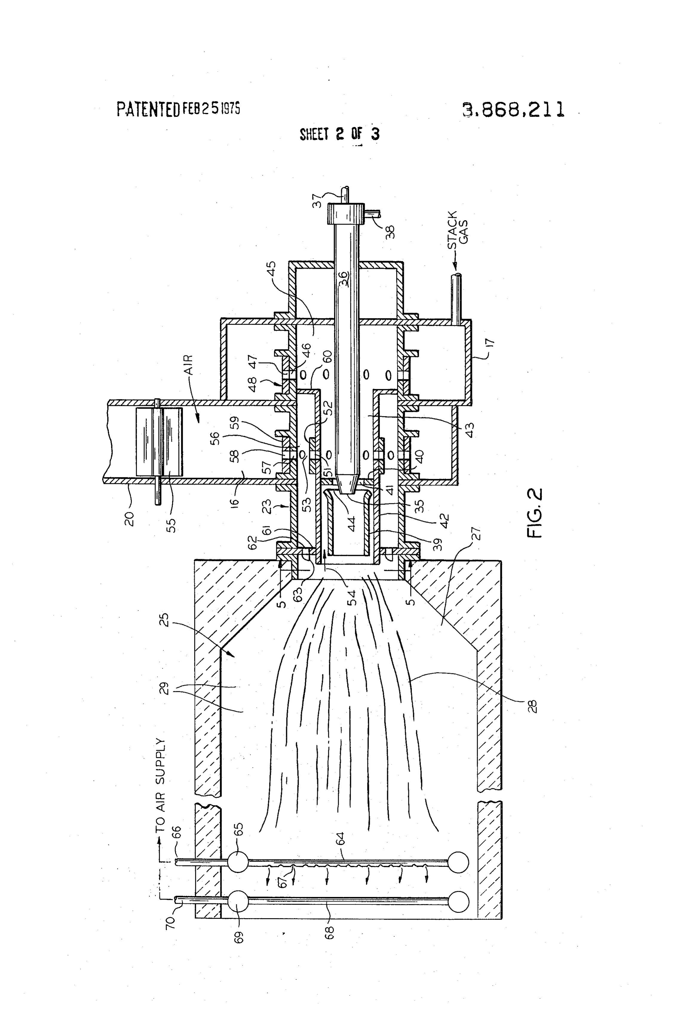
FIG. 2 shows a fragmentary cross ‘section of a combustion chamber and an associated burrier adapted for stack gas recirculation in accordance with the invention;
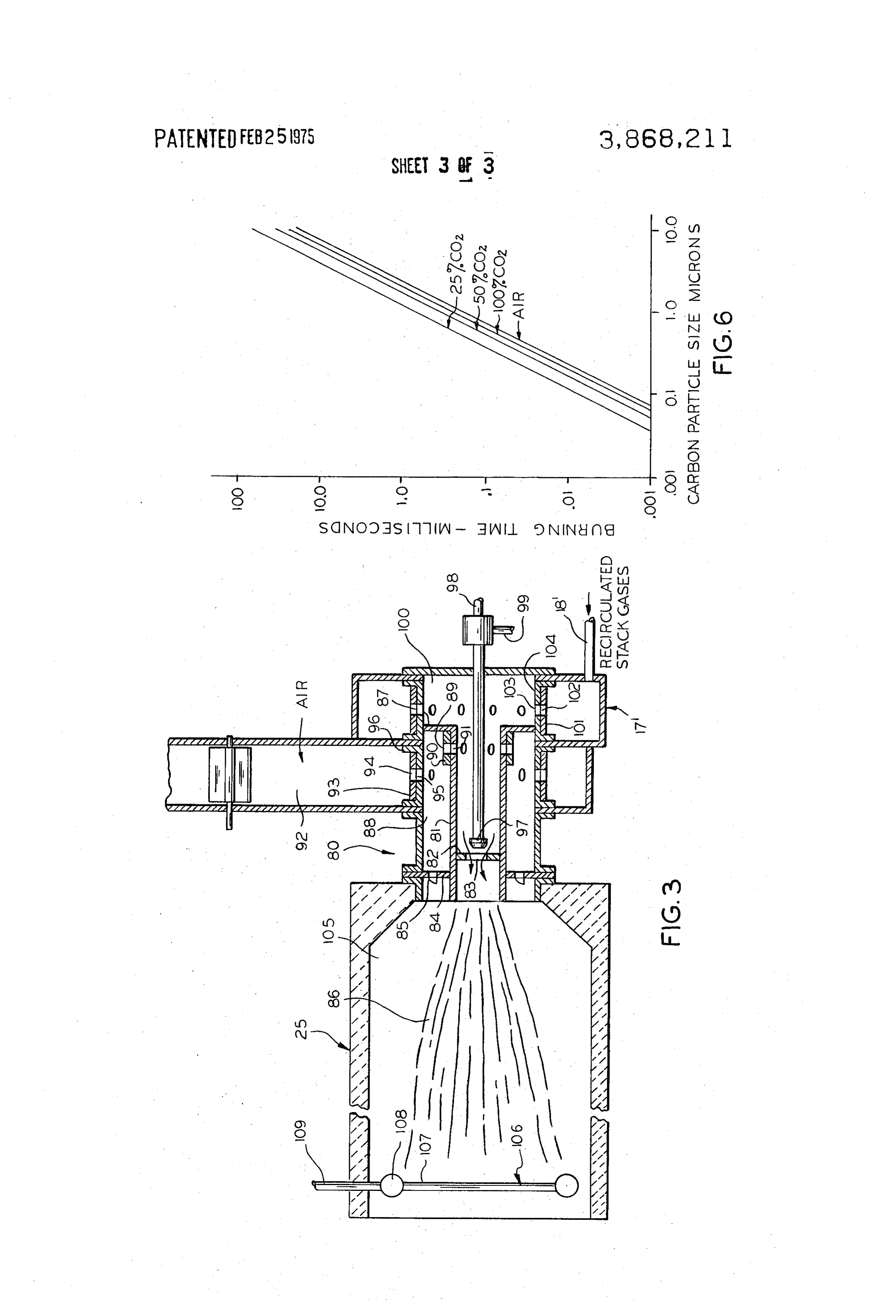
FIG. 3 is similar to the preceding figure except that a different kind of burner arrangement is shown;
FIG. 4 is a fragmentary longitudinal section of a combustion chamber adapted for use of recirculted stack gases;
FIG. 5 is a plan view of an aperture plate used in the burner assemblies of FIGS. 2 and 3 as specifically exemplified by viewing in the direction of the plane 5—5 in FIG. 2; and
FIG. 6 is a graph showing burning time versus carbon particle size for various percentages of combustion supporting carbon dioxide and air.
DESCRIPTION OF A PREFERRED
_ EMBODIMENT
The invention is based on recirculating exhaust gases - from a combustor stack to one or more air inlets in the combustion zone which burns the fuel in stages under different controlled conditions calculated to reduce both carbon and nitrogen oxide in the stack gases.
The invention is applicable to a variety of fuel burning devices but will be described in reference to boilers or steam generators such as depicted in FIG. 1. Except for the combustion chamber and the manner in which the fuel and gases for combustion are handled, the
Page 6
boiler in FIG. 1 is substantially conventional. This boiler is for producing hot water or steam and includes a shell or housing 10 constituting an enclosure for an upper drum 11 and a lower drum 12. The drums are connected by means of a plurality of water filled tubes 13 on the foreground side and another plurality of tubes, not visible, on the background side. The tubes have membranes or web plates 14 welded between them to define a cavity in which heat is derived by the tubes from hot combustion gases discharged from a combustion chamber and by radiation from the combustion chamber. The exhaust gases, after most of their heat is extracted, are discharged to the atmosphere through a stack 15 which is shown fragmentarily.
The front end, to the right in FIG. 1, of the boiler has an air plenum 16 and a recirculated stack gas plenum 17. The stack gas plenum 17 is supplied with stack gas through a pipe 18 which junctions with the stack pipe 15 near the top of the boiler housing so that gas at temperatures at least in the range of 60°C to 400°C will be available from the stack. Stack gas pipe 18 may have a valve 19 installed in it which valve in this case is merely symbolized.as a manual one but it will be understood that it may be subject to automatic throttling. A low pressure blower 20 may be used under some circumstances to force the stack gases from the stack 15 to plenum 17.
Air plenum 16 has an internal fan blade 20 driven by a motor 21. This fan draws atmospheric air through a grille 22 and directs the air downwardly in plenum 16 for introduction through one or more air injection ports associated with a fuel burner which is generally designated by the numeral 23 in FIG. 1. The fuel burner will be described in detail later.
The combustion chamber of the boiler comprises a refractory housing 25 having a cylindrical interior 26. It should be understood that the combustion chamber 25 need not be of the refractory lined type but may be simply defined by the boiler tubes or may be a water jacket type having inner and outer shells, not shown, between which water flows for directly absorbing heat by radiation and convection from the flame within the combustion chamber. The fuel and combustion gas inlet end of combustion chamber 25 preferably has a conical shape marked 27 although this is not indispensible insofar as application of the principles of the inven-
. tion are concerned.
Combustion chamber 25 is characterized by combusting the gases and fuel in stages in this example. In accordance with the invention, the fuel is injected into combustion chamber 25 along with air or stack gases or a mixture thereof. In one stage of combustion, the fluid fuel, being injected with much less air than is required for complete combustion, burns as a central core of flame which is indicated by the centrally heavily shaded region in FIG. 1 marked with the numeral 28. The shortage of air for complete combustion in core 28 results in a relatively low temperature core flame near burner 23 where the core has not undergone significant turbulence that would result in its expansion and diffusion with air or other combustion supporting gas in the chamber. As the core of hot gases progresses down the interior 26 of the combustion chamber heat is transferred, primarily by radiation, to the walls of the furnace and then to the tubes 13 and there is increased turbulence, expansion and mixing with a surrounding sheath of air or stack gases injected in such manner as
to surround and mix with the core 28. Stack gases are not intentionally mixed. with sheathing air but some mixing is inevitable. Mixing of stack gas with sheathing air was found to have minimal effect on the results desired and wasteful of the stack gases. Ths surrounding or sheathing air follows the peripheral region 29 and this gas ultimately mixes with the core gas, containing recirculated stack gases and products of partially burned fuel, near the exit end of the combustion chamber where more complete combustion occurs.
A characteristic resulting from isolation of the sheath air 29 from the hotter gaseous combustion products in core 28 is that the oxygen which is available from the air in the core has a tendency to combine with the hydrocarbons from the fuel in preference to nitrogen from the air in which case substantial amounts of carbon monoxide and some carbon dioxide are produced but relatively low amounts of the various nitrogen Oxides are produced. There is also substantial unburned carbon in the flame core at this time. Low production of nitrogen oxide results from the fuel rich mixture in the core 28 burning at a temperature sufficiently below 1,375°C that the reaction between nitrogen and oxygen is inhibited.
In the region of the combustion chamber downstream from burner 23, after significant heat has been extracted from the core by radiation and convection, mixing of the sheath air 29 and the core gases is encouraged in which case oxygen available from the sheath gas combines with most carbon, other unburned hydrocarbons from the fuel and carbon monoxide to effectuate more complete combustion but, again, at a much lower temperature than would occur if all of the combustion air were mixed with the fuel initially in accordance with conventional practice. In the present case, it is only after substantial heat has been extracted from the core flame that complete combustion is allowed to occur. Hence, combustion of residual’ carbon monoxide to carbon dioxide and the combustion of possibly surviving unburned hydrocarbons . occurs where the combustion gases are diffused and ‘at low temperature so that production of nitrogen oxides is inhibited. However, under some operating conditions, carbon from the fuel may not be completely oxidized and this is manifested in the stack gases being smoky which is undesirable. The present invention is concerned with obtaining more complete combustion of the carbon without sacrificing the good nitrogen oxides inhibiting characteristics of the staged combustion process.
In accordance with one aspect of the invention, stack gases are recirculated to the burner chamber and these gases are primarily injected into the flame core 28 to obtain smoke control. The good results obtained in reducing smoke emitted by stack 15 are believed. to be due to the reaction of CO, (carbon dioxide) in the recirculated stack gases with the fine carbon particles in the flame core before and after diffusion to thereby form CO (carbon monoxide) which, according to the invention, is caused to burn cleanly later to COs. It is known that CO, may be used as an oxidant for carbon and that carbon will burn in 100 percent CO, at about the rate that it burns in air. When the CO, level is lower than 100 percent as when it is derived from stack gas, it has been found to be still adequate to burn out small particles around one micron in size in less than 10 milliseconds which is rapid enough to obtain burnout of
Page 7
such particles in boiler furnaces. Carbon particles in smoke resulting from burning hydrocarbon fuels in gaseous form are usually about 0.05 microns in size. Carbon particles resulting from burning liquid hydrocarbon fuel are usually in the size range of | to 10 microns and some particles are formed within droplets of fuel. The relationship between the burning time in milliseconds and carbon particle size in the presence of 25, 50 and 100 percent CO, and in the presence of air for carbon particles ranging from .01 to 10.0 microns is shown graphically in FIG. 6. The burning times are calculated and are based on the following equation:
where d = the pellet diameter at time ¢.
d= initial pellet diameter.
t = burning time.
k is an empirical combustion rate constant peculiar to each fuel and burning condition.
The values of k used in the calculations were derived from data in “The Interaction Between Carbon and Carbon Dioxide and Oxygen at Temperatures Up to 3,000°K” by E. S. Yolovinz and G. P. Khaustovich, Eighth Symposium (International) on Combustion,
Carbon burning in air or CO, reaches a maximum combustion rate in the range of 1,200° to 1,400°C. At 1,300°C the rate is nearly maximum. Above these temperatures, the rate appears to remain substantially constant.
It has been found that by injecting recirculated exhaust or stack gases at a temperature of about 60°C to 90°C into the combustion gases that both low smoke and low nitrogen oxides are achieved. The process involves mixing recirculated carbon dioxide containing stack gases in the core 28 of the above described combustion process. Various kinds of apparatus for practicing the stack gas recirculating method will now be discussed.
Refer to FIG. 2 which shows one type of burner assembly 23 associated with a combustion chamber 25 similar to the one depicted in FIG. 1. In FIG. 2, the
burner comprises a nozzle body 36 having a tip 35 from.
which a mixture of fuel and an atomizing gas such as high pressure air is emitted for the purpose of combustion in combustion chamber 25. From the remote end of nozzle body 36, the nozzle tip 35 is supplied with fluid fuel through a pipe 37 and the atomizing or vaporizing substance through a pipe 38. Adjacent to nozzle tip 35 is a hollow cylinder or sleeve 39 through which the fuel is projected into combustion chamber 25 where it burns. Sleeve 39 may be omitted without seriously affecting smoke when No. 2 fuel oil is used although flame color changes from blue to yellow. Sleeve 39 is omitted when using No. 2 fuel to prevent the accretion. Air and CO, individually or jointly, according to the invention, are directed through sleeve 39 for supporting combustion in the flame core which, as in FIG. 1, is marked with the reference numeral 28. These combustion supporting gases are admitted through a diaphragm 40 having an aperture 41. The gases are proportioned as will be explained. Diaphragm 40 extends across a hollow cylinder 42 which surrounds a portion of the nozzle body and is spaced in essentially concentric relationship with sleeve 39. The rear interior portion 43 of hollow cylinder 42 is arranged for enabling conducting air, stack gas containing CO, and mixtures of these gases as desired to aperture 41. As in-
dicated above, air flow is normally so regulated that much less than the stoichiometric quantity of air is supplied to the core flame 28 to thereby inhibit production of nitrogen oxides. The amount of recirculated co, containing stack gas is so controlled as to promote oxidation or burning of carbon in the core 28 independently of the air of combustion. Thus, CO, is introduced into the core flame 28 by recirculation of stack gas for reaction with carbon in the core flame which results in production of carbon monoxide in quantities significantly greater than would occur if all of the air for combustion of the fuel were mixed with the fuel according to conventional practice. Some carbon dioxide containing combustion gases also recirculate into the core as a result of a venturi effect which occurs in the vicinity of aperture 41 and the mouth 44 of sleeve 39, In other words, some CO, containing gas reverts back in a direction indicated by the arrow 54 and follows the concentric space between cylinder 42 and sleeve 39 after which it reenters the sleeve and mixes with the fuel which is being projected therethrough. This contributes to the carbon and CO, reaction to some extent. Since this same gas contains substantial heat, it aids significantly to vaporize the fuel to equilibrium within the sleeve.
The burner assembly 23 which is symbolically depicted in FIG. 2 has a hollow region 43 upstream for enabling directing air or stack gas or both through aperture 41. Hollow region 43 communicates with another chamber 45 which is surrounded by the stack gas plenum 17, Chamber 45 may be cylindrical and provided with a plurality of holes 46 which can be aligned and misaligned with a similar plurality of holes 47 in a rotatable sleeve 48. Since the holes 46 and 47 are circumferentially spaced from each other, it is possible to rotate sleeve 48 in such manner as to completely align holes 46 and 47 or misalign them to regulate the stack gas that can enter region 43. This permits control or throttling of the amount of carbon dioxide containing stack gas which is admitted to flame core 28.
A selected amount of combustion air may also be admitted to flow out through aperture 41 for supporting combustion in the core 28 of fuel injected from nozzle tip 35. For this purpose, cylinder 42 is provided with a plurality of circumferentially spaced holes 51 which are surrounded by a sleeve 52 in which there are also a plurality of circumferentially spaced radial holes 53. Sleeve 52 may be rotated to adjust the quantity of air that is admitted to aperture 42 for supporting combustion in the core flame 28.
Air is obtainable from a pressurized plenum 16 in which there also may be a control damper 55 that can grossly regulate the amount of air provided by fan 20 in the plenum. Air from plenum 16 flows into a cavity 56 through a plurality of holes 57 in the burner housing wall which can be made to align or misalign with a plurality of holes 58 in a rotatable sleeve 59 for regulating air input. ;
A radial flange 60 extending from cylinder 42 together with a perforated aperture plate 61 defines air cavity 56. In accordance with the invention, much of the air needed for complete combustion of the fuel is supplied to the combustion zone through a plurality of perforations 62 in the plate 61. A plan view of the plate is shown in FIG. 5 where it can be seen that it has a plurality of apertures 62 which may be formed by piercing the parent metal so as to produce angularly and axially
Page 8
extending vanes 63 which cause air projected through the apertures to be deflected radially of the flame core 28 and to form a helically advancing sheath about it. Any suitable means may be substituted for the specific perforated plate 61 to produce the slowly rotating sheath of air which follows along flame core 28 and surrounds it through most of the combustion zone until mixing eventually occurs. In some configurations, the component of rotation may be such as to approach or reach zero. As mentioned earlier, near the burner assembly 23 the air flowing through the aperture plates 61 and the core flame remain fairly well isolated and can be called a sheath, but as the flame is propagated down the combustion zone there is significant mixing of the air and core, after heat has been extracted from the latter, to effectuate combustion of unburned components at a temperature which inhibits production of nitrogen oxides. Also, the carbon dioxide from the stack gases reacts with carbon present in the combustion zones to produce substantial carbon monoxide which is ultimately oxidized to carbon dioxide before it is returned to the stack as will be explained.
It will be evident that some stack gas may be injected through the apertured plate 61 by suitably balancing the air pressure and stack gas pressure in their respective plenums 16 and 17. As the air or air and CO containing exhaust gases in sheath 29 progresses down the combustion chamber away from the burner, and as the CO rich core 28 expands in the same zone, some turbulence and intermixing occurs which promotes combustion of residual combustion products. In this zone the temperature required for the maximum reaction of CO and carbon to produce CO are over 1,250 C so production of CO is relatively high.
It is necessary to react the CO with oxygen containing gas to reconvert it to CO before the gaseous combustion products are returned to the stack and the atmosphere. Downstream from the zone where maximum reaction between. CO and carbon takes place, the gases undergo further cooling by radiation and convection, It is thus. possible to oxidize the CO again under relatively low temperature conditions which result in CO being produced but at temperatures not so high that significant nitrogen oxides are produced.
It has been found that thorough mixing of the gases far downstream in the combustion zone results in oxidation of the CO at the desired temperatures. This is done by promoting mixing of the gases by physical obstructions or by injecting secondary air into the gaseous combustion product stream or both. Good turbulence and intermixing may be obtained by interposing screen or grid means, sometimes referred to as a “flame holder,” across the combustion product screen near the end of the combustion chamber as illustrated in FIG. 4. In this figure the combustion chamber 25 has a screen means or perforated grid 71 of refractory material interposed in the combustion gas stream remote from the burner. The perforations 72 in the screen means, of course, result in a gas velocity increase from the combustion chamber side to the discharge side and this promotes the turbulence external to the chamber which results in more complete oxidation of the carbon - monoxide and any other combustion products that may remain in the combustion gases. Generally a grid means that produces a pressure drop of about 0.3 percent of the furnace upstream pressure just beyond cone 27 or
2 inches of water pressure for boiler furnaces operating
at essentially atmospheric pressure will produce the necessary turbulence and intermixing.
In FIG. 2, a plurality of parallel pipes 64 are interposed across the gaseous combustion product stream for inducing mixing of the gases. The spacing between the pipes 64 is such that the pressure drop approximating that mentioned above is produced. In cases where the combustion chamber 25 is large, merely producing a pressure drop may not result in sufficient mixing with combustion air and complete oxidation of the carbon monoxide and other unburned products so it is desirable to introduce the final amount of air for combustion by means of parallel pipes 64. Thus, the parallel pipes 64 in FIG. 2 may be connected to a header 65 which received a supply of air through a pipe 66 from the air plenum 16, for instance. When the pipes 64 are used to inject air rather than merely as a means for producing a pressure drop, they are provided with rows of small holes 67 on the downstream side or at the sides. Air is emitted from the holes for the purpose of completing the oxidation of carbon monoxide and other residual burnable products. In some combustion devices, it is desirable to have two stages of secondary air injection and, as shown in FIG. 2, the combustion chamber may be provided with a second set of perforated pipes 68 connected to another header 69 which receives an air supply through an input pipe 70. The amount of air fed through the second pipe 70 is usually less than that which is supplied through the first supply pipe 66 since usually a sufficient quantity of air is emitted from pipes 68 for completing oxidation of only small quantities of incompletely oxidized combustible substances.
Secondary air for burning carbon or other combustibles under turbulent conditions and at comparatively low temperature remote from the burner may also be introduced through orifices 73 in the combustion chamber 25 wall as shown in FIG. 4. The orifices may be supplied from a header 74 which is connected to the air plenum 16 by suitable pipe means, not shown.
The new method involving recirculation of CO containing stack gas may be practiced with various types of fluid fuel burners. The burner just described in connection with FIG. 2 is especially well adapted to burning highly volatile fuels such as No. 2 fuel oil for obtaining low carbon particulates, CO and nitrogen oxides by properly proportioning recirculated exhaust gases and air for combustion through apertured plate 61 and the air injecting grids 64 and 68 or, in some Cases, by merely producing turbulence with a pressure ‘drop through a grid. Other burner configurations are more appropriate for reducing carbon and nitrogen oxides in the exhaust gases when less volatile fuels such as No. 6 fuel oil is used. Practicing the new stack gas recirculation method under these circumstances will now be discussed in reference to FIG. 3. ;
In FIG. 3, the burner assembly is generally designated by the reference numeral 80. It comprises an inner hollow cylinder 81 across which fuel and combustion air and carbon dioxide containing exhaust gas may be projected into combustion chamber 25 . The exterior of cylinder 81 is surrounded by an input gas distributor or aperture plate 84 having a plurality of perforations 85 for projecting air about the periphery of the flame core 86 which, in this case as in the previous case, comprises a mixture that is low in combustion air content and rich in fuel so that it burns at relatively low temperature and thereby inhibits nitrogen oxides production.
Page 9
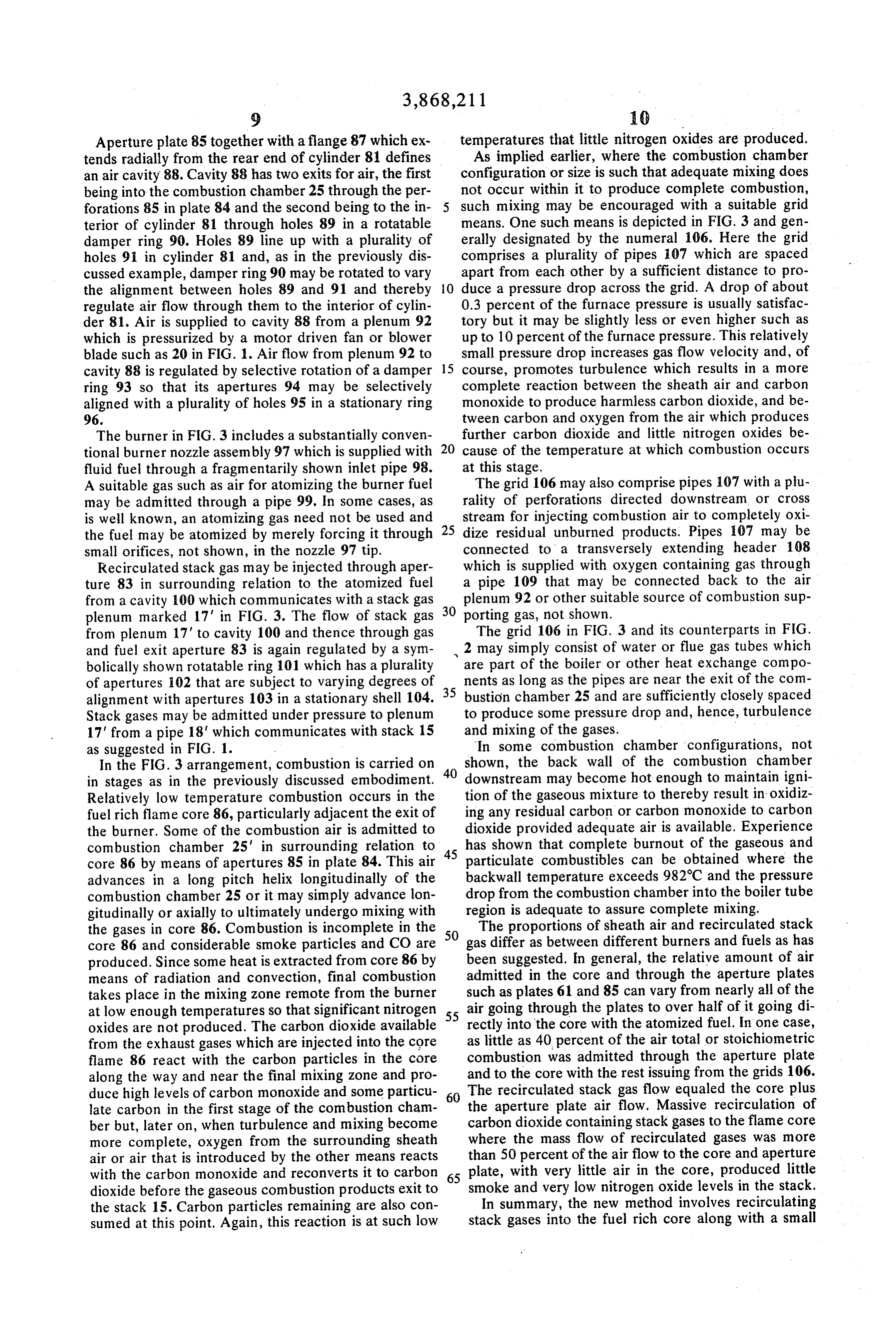
Aperture plate 85 together with a flange 87 which extends radially from the rear end of cylinder 81 defines an air cavity 88. Cavity 88 has two exits for air, the first being into the combustion chamber 25 through the perforations 85 in plate 84 and the second being to the interior of cylinder 81 through holes 89 in a rotatable damper ring 90. Holes 89 line up with a plurality of holes 91 in cylinder 81 and, as in the previously discussed example, damper ring 90 may be rotated to vary the alignment between holes 89 and 91 and thereby regulate air flow through them to the interior of cylinder 81. Air is supplied to cavity 88 from a plenum 92 which is pressurized by a motor driven fan or blower blade such as 20 in FIG. 1. Air flow from plenum 92 to cavity 88 is regulated by selective rotation of a damper ring 93 so that its apertures 94 may be selectively aligned with a plurality of holes 95 in a stationary ring
The burner in FIG. 3 includes a substantially conventional burner nozzle assembly 97 which is supplied with fluid fuel through a fragmentarily shown inlet pipe 98. A suitable gas such as air for atomizing the burner fuel may be admitted through a pipe 99. In some cases, as is well known, an atomizing gas need not be used and the fuel may be atomized by merely forcing it through small orifices, not shown, in the nozzle 97 tip.
Recirculated stack gas may be injected through aperture 83 in surrounding relation to the atomized fuel from a cavity 100 which communicates with a stack gas plenum marked 17’ in FIG. 3. The flow of stack gas from plenum 17' to cavity 100 and thence through gas and fuel exit aperture 83 is again regulated by a symbolically shown rotatable ring 101 which has a plurality of apertures 102 that are subject to varying degrees of alignment with apertures 103 in a stationary shell 104. Stack gases may be admitted under pressure to plenum 17' from a pipe 18‘ which communicates with stack 15 as suggested in FIG. 1.
In the FIG. 3 arrangement, combustion is carried on in stages as in the previously discussed embodiment. Relatively low temperature combustion occurs in the fuel rich flame core 86, particularly adjacent the exit of the burner. Some of the combustion air is admitted to combustion chamber 25' in surrounding relation to core 86 by means of apertures 85 in plate 84. This air advances in a long pitch helix longitudinally of the combustion chamber 25 or it may simply advance longitudinally or axially to ultimately undergo mixing with the gases in core 86. Combustion is incomplete in the core 86 and considerable smoke particles and CO are produced. Since some heat is extracted from core 86 by means of radiation and convection, final combustion takes place in the mixing zone remote from the burner at low enough temperatures so that significant nitrogen oxides are not produced. The carbon dioxide available from the exhaust gases which are injected into the core flame 86 react with the carbon particles in the core along the way and near the final mixing zone and produce high levels of carbon monoxide and some particulate carbon in the first stage of the combustion chamber but, later on, when turbulence and mixing become more complete, oxygen from the surrounding sheath air or air that is introduced by the other means reacts with the carbon monoxide and reconverts it to carbon dioxide before the gaseous combustion products exit to the stack 15. Carbon particles remaining are also consumed at this point. Again, this reaction is at such low
temperatures that little nitrogen oxides are produced.
As implied earlier, where the combustion chamber configuration or size is such that adequate mixing does not occur within it to produce complete combustion, such mixing may be encouraged with a suitable grid means. One such means is depicted in FIG. 3 and generally designated by the numeral 106. Here the grid comprises a plurality of pipes 107 which are spaced apart from each other by a sufficient distance to produce a pressure drop across the grid. A drop of about 0.3 percent of the furnace pressure is usually satisfactory but it may be slightly less or even higher such as up to 10 percent of the furnace pressure. This relatively small pressure drop increases gas flow velocity and, of course, promotes turbulence which results in a more complete reaction between the sheath air and carbon monoxide to produce harmless carbon dioxide, and between carbon and oxygen from the air which produces further carbon dioxide and little nitrogen oxides because of the temperature at which combustion occurs at this stage.
The grid 106 may also comprise pipes 107 with a plurality of perforations directed downstream or cross stream for injecting combustion air to completely oxidize residual unburned products. Pipes 107 may be connected to'a transversely extending header 108 which is supplied with oxygen containing gas through a pipe 109 that may be connected back to the air plenum 92 or other suitable source of combustion supporting gas, not shown.
The grid 106 in FIG. 3 and its counterparts in FIG. 2 may simply consist of water or flue gas tubes which are part of the boiler or other heat exchange components as long as the pipes are near the exit of the combustion chamber 25 and are sufficiently closely spaced to produce some pressure drop and, hence, turbulence and mixing of the gases. ,
‘In some combustion chamber ‘configurations, not shown, the back wall of the combustion chamber downstream may become hot enough to maintain ignition of the gaseous mixture to thereby result in-oxidizing any residual carbon or carbon monoxide to carbon dioxide provided adequate air is available. Experience has shown that complete burnout of the gaseous and particulate combustibles can be obtained where the backwall temperature exceeds 982°C and the pressure drop from the combustion chamber into the boiler tube region is adequate to assure complete mixing.
The proportions of sheath air and recirculated stack gas differ as between different burners and fuels as has been suggested. In general, the relative amount of air admitted in the core and through the aperture plates such as plates 61 and 85 can vary from nearly all of the air going through the plates to over half of it going directly into the core with the atomized fuel. In one case, as little as 40. percent of the air total or stoichiometric combustion was admitted through the aperture plate and to the core with the rest issuing from the grids 106. The recirculated stack gas flow equaled the core plus the aperture plate air flow. Massive recirculation of carbon dioxide containing stack gases to the flame core where the mass flow of recirculated gases was more than 50 percent of the air flow to the core and aperture plate, with very little air in the core, produced little smoke and very low nitrogen oxide levels in the stack.
In summary, the new method involves recirculating stack gases into the fuel rich core along with a small
Page 10
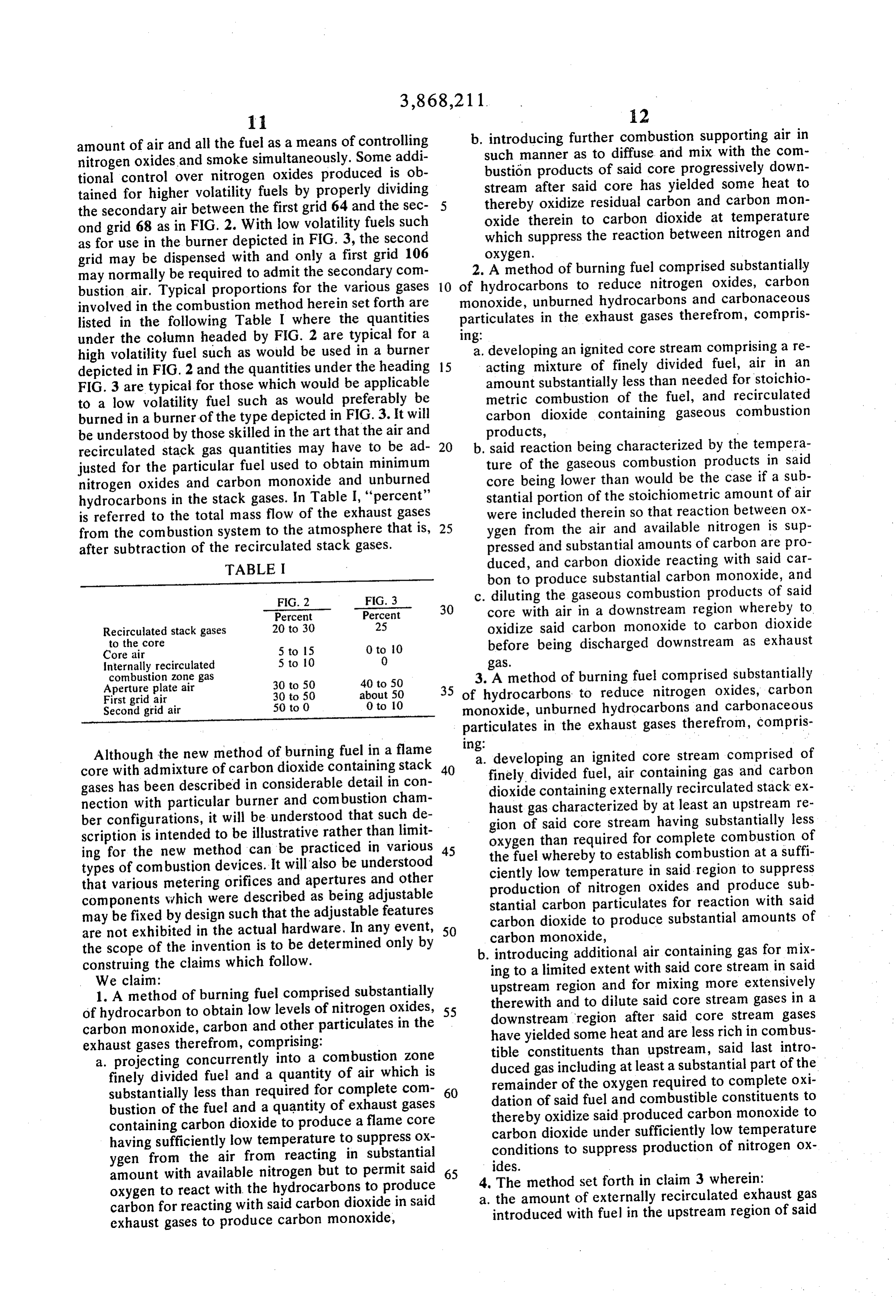
amount of air and all the fuel as a means of controlling nitrogen oxides and smoke simultaneously. Some additional control over nitrogen oxides produced is obtained for higher volatility fuels by properly dividing the secondary air between the first grid 64 and the second grid 68 as in FIG, 2. With low volatility fuels such as for use in the burner depicted in FIG. 3, the second grid may be dispensed with and only a first grid 106 may normally be required to admit the secondary combustion air. Typical proportions for the various gases involved in the combustion method herein set forth are listed in the following Table I where the quantities under the column headed by FIG. 2 are typical for a high volatility fuel such as would be used in a burner depicted in FIG. 2 and the quantities under the heading FIG. 3 are typical for those which would be applicable to a low volatility fuel such as would preferably be burned in a burner of the type depicted in FIG. 3. It will be understood by those skilled in the art that the air and recirculated stack gas quantities may have to be adjusted for the particular fuel used to obtain minimum nitrogen oxides and carbon monoxide and unburned hydrocarbons in the stack gases. In Table I, ‘‘percent” is referred to the total mass flow of the exhaust gases from the combustion system to the atmosphere that is, after subtraction of the recirculated stack gases.
TABLE I
Percent Percent
Recirculated stack gases 20 to 30 25 to the core
Internally recirculated 5 to 10 0 combustion zone gas
Aperture plate air 30 to 50 40 to 50
First grid air 30 to 50 about 50
Second grid air 50 to 0 0 to 10
Although the new method of burning fuel in a flame core with admixture of carbon dioxide containing stack gases has been described in considerable detail in connection with particular burner and combustion chamber configurations, it will be understood that such description is intended to be illustrative rather than limiting for the new method can be practiced in various types of combustion devices. It will also be understood that various metering orifices and apertures and other components which were described as being adjustable may be fixed by design such that the adjustable features are not exhibited in the actual hardware. In any event, the scope of the invention is to be determined only by construing the claims which follow.
We claim:
1. A method of burning fuel comprised substantially of hydrocarbon to obtain low levels of nitrogen oxides, carbon monoxide, carbon and other particulates in the exhaust gases therefrom, comprising:
a. projecting concurrently into a combustion zone finely divided fuel and a quantity of air which is substantially less than required for complete combustion of the fuel and a quantity of exhaust gases containing carbon dioxide to produce a flame core having sufficiently low temperature to suppress OXygen from the air from reacting in substantial amount with available nitrogen but to permit said oxygen to react with. the hydrocarbons to produce carbon for reacting with said carbon dioxide in said exhaust gases to produce carbon monoxide,
b. introducing further combustion supporting air in such manner as to diffuse. and mix with the combustién products of said core progressively downstream after said core has yielded some heat to thereby oxidize residual carbon and carbon monoxide therein to carbon dioxide at temperature which suppress the reaction between nitrogen and oxygen.
2. A method of burning fuel comprised substantially of hydrocarbons to reduce nitrogen oxides, carbon monoxide, unburned hydrocarbons and carbonaceous particulates in the exhaust gases therefrom, comprising:
a. developing an ignited core stream comprising a reacting mixture of finely divided fuel, air in an amount substantially less than needed for stoichiometric combustion of the fuel, and recirculated carbon dioxide containing gaseous combustion products, :
b. said reaction being characterized by the temperature of the gaseous combustion products in said core being lower than would be the case if a substantial portion of the stoichiometric amount of air were included therein so that reaction between oxygen from the air and available nitrogen is suppressed and substantial amounts of carbon are produced, and carbon dioxide reacting with said carbon to produce substantial carbon monoxide, and
c. diluting the gaseous combustion products of said core with air in a downstream region whereby to. oxidize said carbon monoxide to carbon dioxide before being discharged downstream as exhaust gas.
3. A method of burning fuel comprised substantially of hydrocarbons to reduce nitrogen oxides, carbon monoxide, unburned hydrocarbons and carbonaceous particulates in the exhaust gases therefrom, comprising: oe
a. developing an ignited core stream comprised of finely divided fuel, air containing gas and carbon dioxide containing externally recirculated stack exhaust gas characterized by at least an upstream region of said core stream having substantially less oxygen than required for complete combustion of the fuel whereby to establish combustion at a sufficiently low temperature in said region to suppress production of nitrogen oxides and produce substantial carbon particulates for reaction with said carbon dioxide to produce substantial amounts of carbon monoxide,
b. introducing additional air containing gas for mixing to a limited extent with said core stream in said upstream region and for mixing more extensively therewith and to dilute said core stream gases in a downstream region after said core stream gases have yielded some heat and are less rich in combustible constituents than upstream, said last introduced gas including at least a substantial part of the remainder of the oxygen required to complete oxidation of said fuel and combustible constituents to thereby oxidize said produced carbon monoxide to carbon dioxide under sufficiently low temperature conditions to suppress production of nitrogen oxides.
4, The method set forth in claim 3 wherein:
a. the amount of externally recirculated exhaust gas introduced with fuel in the upstream region of said
Page 11
core stream is about 10 to 30 percent the total mass flow of exhaust gases resulting from burning said fuel under the conditions set forth.
5. The method set forth in claim 3 including:
a. internally recirculating a portion of the hot gaseous combustion products from said upstream region of said core further upstream and in proximity with said fuel to aid in vaporizing and preparing said fuel for combustion.
6. The method set forth in claim 3 wherein:
a. the amount of air introduced with fuel in the upstream regions of said core stream is in the range of about 5 to 15 percent of the total mass flow of stack discharged exhaust gases resulting from burning said fuel under the conditions set forth.
7. The method set forth in claim 3 wherein:
a. the amount of air introduced in said additional air including gas stream for mixing with said core stream as aforesaid is 30 to 50 percent in terms of stack discharged mass flow of exhaust gases resulting from burning said fuel under the conditions set forth.
8. The method set forth in.claim 3 including the step
a. passing said gases resulting from the core stream and the air including gas stream through means for producing a pressure drop and, hence, increased gas velocity and turbulence downstream for thereby promoting further mixing and more complete combustion of said gaseous mixture.
9, The method set forth in claim 3 including:
a. introducing a first quantity of air continuously to diffuse and mix with the gaseous combustion products downstream of the region where there is substantial mixing of said additional air and the combustion products of said core stream.
10. The method set forth in claim 9 wherein:
a. the amount of air introduced as said first quantity is about from 0 to 50 percent of the total mass flow of exhaust gases resulting from burning said fuel under the conditions set forth.
11. The method set forth in claim 9 including:
a. introducing a second quantity of air continuously to diffuse and mix next downstream with the gaseous combustion products resulting from admixture of said first quantity of air.
12. The method set forth in claim 11 wherein:
a. the amount of air introduced as said second quantity of air is about 0 to 50 percent of the stack discharged mass flow of exhaust gases. ;
13. The method set forth in claim 3 especially
adapted for burning high specific gravity liquid fuels such as No. 6 fuel oil and the like, wherein:
a. the amount of exhaust gases introduced with said fuel in the upstream portion of said core stream is about 25 percent of the stack discharged mass flow of exhaust gases resulting from burning said fuel under the conditions set forth.
14. The method set forth in claim 13 wherein:
a. the amount of said additional air introduced to mix with said core stream downstream is from 40 to 50 percent of the stack discharged mass flow of exhaust gases resulting from burning said fuel under the conditions set forth.
15. The method set forth in claim 13 wherein:
a. the amount of air introduced in said core stream along with said fuel and carbon dioxide containing
exhaust gas is about 0 to 10 percent of the total mass flow of exhaust gases resulting from burning said fuel under the conditions set forth.
16. The method set forth in claim 13 including:
a. introducing a first quantity of air continuously. to diffuse and mix with the gaseous combustion products downstream of the region where there is substantial mixing of said additional air and the combustion products of said core stream.
17. The method as set forth in claim 3 wherein:
a. said additional air is introduced as a stream surrounding said core stream and flowing confluently therewith. .
18. The method set forth in claim 3 wherein:
a. said exhaust gases are introduced into said core stream at a temperature of 60° to 400°C.
19. Apparatus for burning fuel comprised substantially of hydrocarbons to obtain low levels of nitrogen oxides, carbon monoxide and unburned substances in the exhaust gases therefrom, comprising:
a. means defining a combustion zone having an exit for gaseous combustion products produced therein, :
b. burner means coupled with said combustion. zone defining means, said burner means including means for injecting fuel into said zone and means defining passageways for selectively injecting gases selected from the group of carbon dioxide containing gaseous combustion products and air and mixtures thereof into said zone concurrently with said fuel,
c. at least a first one of said gas passageway defining means being for flowing gas including carbon dioxide from an upstream direction of said injecting means and past said injecting means in surrounding relationship therewith and concurrently with said fuel to effect an ignited core stream for progressing through said combustion zone, :
d. a second one of said gas passageways being for introducing at least one of said gases into said combustion zone contiguous with said core stream for reacting with constituents thereof, and
e. means for returning to said first passageway a portion of the carbon dioxide containing gaseous exhaust products resulting from combustion in said zone and exiting therefrom.
20. The apparatus set forth in claim 19 wherein:
a. said fuel injecting means comprise nozzle means having orifice means directed to said combustion zone;
b. said first one of said passageway defining means comprising diaphragm means having an aperture aligned with said nozzle means, whereby to direct said combustion supporting gas confluently with said fuel to enable generation of said core stream.
21. The apparatus set forth in claim 19 wherein:
a. said fuel injecting means comprise nozzle means having orifice means directed to said combustion zone,
b. said first one of. said gas passageway defining means including a cylinder means aligned with said nozzle means and arranged relative to said nozzle means such that fuel and gas including said carbon dioxide may flow confluently. therethrough into said combustion zone to form said core stream.
22. Apparatus for burning fuel comprised substan-
tially of hydrocarbons to obtain low levels of nitrogen
Page 12
oxides, carbon monoxide and unburned substances in
the exhaust gases therefrom, comprising:
a. means defining a combustion zone having an exit for gaseous combustion products produced therein,
b. burner means coupled with said combustion zone defining means including means for injecting fuel into said zone and means for defining passageways for selectively injecting gases selected from the
of exhaust gas flowing into said passageways.
24. Apparatus for burning fuel comprised substan-
core stream for progressing through said combustion zone, ; .
d. a second one of said gas passageways being for in-.
troducing at least one of said gases into said combustion zone contiguous with said core for reacting with constituents thereof, .
e. means for returning to said first passageway a portion of the gaseous exhaust products containing carbon dioxide resulting from combustion in said
group consisting of carbon dioxide containing gase- 10 zone and exiting therefrom, ; ous combustion products and air and mixtures f. means interposed in the gaseous combustion prodthereof into said zone concurrently with said fuel, uct stream near the exit of said combustion zone c. at least a first one of said gas passageway defining defining means, said interposed means having a means being for flowing gas including carbon diox- plurality of openings for said gases to flow through . ide concurrently with said fuel to effect an ignited 15 to thereby increase velocity and effect mixing of core stream for progressing through said combus- the gases of said core stream and the gases introtion zone, duced to said combustion zone from said second d. a second one of said gas passageways being for in- passageway whereby to enhance oxidation of cartroducing’at least one of said gases into said com- ,, bon monoxide resulting from the reaction of carbustion zone contiguous with said core for reacting bon and carbon dioxide in said core stream. with constituents thereof, ; 25. Apparatus for burning fuel comprised substane. means for returning to said first passageway a por- tially of hydrocarbons to obtain low levels of nitrogen tion of the gaseous exhaust products containing oxides, carbon monoxiee and unburned substances in carbon dioxide resulting from combustion in said ,, the exhaust gases therefrom, comprising: ; zone and exiting therefrom a. means defining a combustion zone having an exit f. said fuel injecting means comprising nozzle means ter gaseous combustion products produced having orifice means directed to said combustion erein, . . .
zone, b. burner means coupled with said combustion zone g. said first one of said gas passageway defining 39 defining means including ee defi for injecting fuel means including a cylinder means aligned with said fa said zone and means for defining pprnakied s. nozzle means and arranged relative to said nozzle fOr Se ectively injecting gases. select _from the means such that fuel and said gas including said group coe tine of carbon Ode OE gasener ous combustion products and air and mixtures carbon dioxide Ma a flow confinently thorethrougs thereof into said zone concurrently with said fuel, stream, and mbustion zone to form Ss ore 35 © at least a first one of said gas passageway defining h. dia hra m means transverse to said cylinder means being for flow ing Bas including carbon diox- ‘means a ° ‘i having an aperture therein which is ide concurrently with said fuel to effect an ignited aligned with said nozzle means said aperture ad core stream for progressing through said combusie . . : y wk na tion zone, mitting said gas including carbon dioxide to said 40 q 4 second one of said gas passageways being for incylinder means for exiting to said combustion zone troducing at least one of said gases into said com- 24 th Stream. + forth in claim 19 wherei bustion zone contiguous.with said core for reacting . The invention set forth in claim 19 wherein: with constituents thereof, oN sd fiat and acond es passes) dting 4, , mean for eating od fir pasgeyy . . . " . . tion of the gaseous exhaust products. containing wih said means for some said portion of said carbon dioxide resulting from combustion in said exhaust gaseous com ustion products, zone and exiting therefrom, b. and means interposed between said gas returning f. first grid means comprised of tube means having a means and passageways for regulating the amount 50 plurality of oxygen containing gas exit holes, said
first grid means being interposed in the gaseous.
combustion product stream remotely downstream
from said burner means to mix said oxygen containing gas into said stream for burning to carbon dioxide a substantial portion of the carbon monoxide which is produced by the reaction between carbon and carbon dioxide in said core stream.
26. Apparatus for burning fuel comprising substantially hydrocarbons to obtain low levels of nitrogen oxides, carbon monoxide and unburned substances in the exhaust gases therefrom, comprising: —
tially of hydrocarbons to obtain low levels of nitrogen oxides, carbon monoxide and unburned substances in the exhaust gases therefrom, comprising:
a. means defining a combustion zone having an exit 5 for gaseous combustion products produced therein, ‘
b. burner means coupled with said combustion zone defining means including means for injecting fuel 6 into said zone and means for defining passageways
for selectively injecting gases selected from the group consisting of carbon dioxide containing gaseous combustion products and air and mixtures thereof into said zone concurrently with said fuel, c. at least a first one of said gas passageway defining means being for flowing gas including carbon dioxide concurrently with said fuel to effect an ignited
a. means defining a combustion zone having an exit for gaseous combustion products formed therein, b. burner means in communication with said combus- | tion zone in its upstream region, said burner means including nozzle means for injecting finely divided fuel in a downstream direction into said combus-
tion zone,
Page 13
c. means having an aperture transverse to the path of fuel emitted from said nozzle,
d. a source of combustion supporting air,
e. a source of carbon dioxide containing exhaust
means being aligned with said aperture for projecting said fuel substantially centrally thereof.
29. A method of burning fuel comprised substantially of hydrocarbons to obtain low levels of nitrogen oxides, carbon monoxide, carbon and other particulates in the exhaust gases therefrom, comprising:
gases resulting from fuel combustion in said zone, 5 a. simultaneously introducing into a combustion zone
f. means for controlling the amounts of air and ex- fuel and a quantity of air which is substantially less haust gases flowing from said sources through said than the air required for complete combustion of aperture so that said fuel and gases and air react to the fuel and a quantity of exhaust gas containing form an ignited core stream which is rich in fuel carbon dioxide to produce a flame core having sufant ae ess et tuck: whereby ae for complete 10 ficiently low rempersture to mnpede reaction be-
’ r € gaseous com- tween oxygen from the air and available nitrogen bustion products resulting in at least the upstream but to permit said oxygen to react with nydrocar. region of said core comprise substantial amounts of bons to produce carbon for reacting with said carcarbon particulates with which said carbon dioxide bon dioxide from said exhaust gas to produce carwill react to form substantial amounts of carbon 15 bon monoxide, ;
monoxide, and . _— b. introducing additional air downstream after said
* cae ne oe ot wid core fhe a eeam core has yielded some heat to thereby promote oxiwhere said core becomes less defined to promote dation of residual carbon and carbon monoxide to
arom ustion of said carbon monoxide. subst 20 30. The method set forth in claim 29 wherein:
. u uel comprisin - ae : ‘ waa: ;
tially hydrocarbons to obtain low levels of nitrogen ox a . agaition a py duanty Provided is substantially Se ee eestor compricine: substances in the for complete combustion of the fuel and the
a. means defining a combustion zone having an exit 25 amount introduced with said fuel to form said for gaseous combustion products formed therein, 31. The method set forth in claim 29 wherein:
b. Durer vreeam oer eee acnch means including a. the quantity of exhaust gas introduced with said nozzle means for i injecting: fuel in a downstream fuel is about 10 to 30 percent of the total mass flow direction into said combustion zone, 30 of exhaust gases resulting from burning said fuel
c. first means constructed and arranged for directing 30 the conditions &. ‘orth 29 including: combustion supporting gases in a generally down- ‘fl wine the busti 4 in stream direction and in surrounding relationship in a owing the gaseous combustion products prorespect to said nozzle means, uced in said combustion zone through means for
d. second means for conducting to said first means 35 producing a pressure drop to thereby increase the less than the amount of oxygen containing air re- velocity of said products and the turbulence | quired for stoichiometric combustion of said fuel thereof for promoting their mixing and, hence, such that the combustion products in an upstream more complete combustion. ; ;
region of said combustion zone resulting from reac- 33. A method of burning fuel comprised substantially tion of said air with said fuel will comprise com- 40 of hydrocarbons to reduce nitrogen oxides, carbon pletely and incompletely oxidized combustion monoxide, unburned hydrocarbons and carbonaceous . products including particulate carbon, particulates in the exhaust gases therefrom, compris-
e. third means for conducting carbon dioxide con- ing. ; oo ;
taining gaseaus combustion products from said a. developing an ignited core stream comprised of combustion zone to said first means for said gase- 45 fuel, air and recirculated exhaust gas which conous combustion products to flow with said air and tains carbon dioxide characterized by at least an for the carbon dioxide therein to react with said upstream region of said core stream having subcarbon in said upstream region to produce carbon stantially less oxygen than is required for complete monoxide in said combustion zone, and combustion of the fuel to impede production of ni-
f. means constructed and arranged for introducing 50 trogen oxides and to produce substantial carbon additional air into said combustion zone separately particulates for reacting with said carbon dioxide from said gases and said fuel for said additional air to yield substantial carbon monoxide, to react with a substantial amount of said carbon b. introducing additional gas comprising air into the monoxide to thereby yield carbon dioxide. combustion products comprising said core stream
28. The apparatus set forth in claim 27 wherein: 55 for said additional air to mix with said combustion
a. said first means comprises a chamber for receiving products to a substantial extent after said products said less than the stoichiometric amount of air and have lost some heat, said additional gas including said carbon dioxide containing gas, at least a substantial part of the remainder of the
b. means in said chamber having an aperture for said oxygen required for complete oxidation of said fuel directing of said gaseous mixture, said nozzle 60 to thereby oxidize said carbon monoxide to carbon
dioxide.
Page 14
UNITED STATES PATENT OFFICE
CERTIFICATE OF CORRECTION
Dated February 25, 1975
Inventor(s) Paul G. La Haye and John W. Bjerklie
It is certified that error appears in the above-identified patent and that said Letters Patent are hereby corrected as shown below:
Column 12, line 6 "temperature" should be "temperatures"
line 27 "and" should be "said"
Colum 14, line 49 ''s' should be ","
Signed and sealed this ]Oth day of June 1975,
(SEAL)
Attest:
C. MARSHALL DANN
RUTH C. MASON Commissioner of Patents
Attesting Officer and Trademarks
Provenance
- Collection
- Cited prior art
- Original assignee
- Aqua Chem Inc
- Original PDF
- patentimages.storage.googleapis.com →
- Filed
- 1974-01-11
- Pages
- 14
- Method
- pdftoppm 300dpi + tesseract 5 (eng)
- Source
- Google Patents bibliographic record
- Granted
- 1975-02-25
- Inventors
- Paul G La Haye; John W Bjerklie; Aqua Chem Inc
- Transcribed from
- patentimages.storage.googleapis.com →