patent · US4326483
Internal combustion engine with oxidant manufacture
27 April 1982
Page 1 — bibliographic record
United States Patent (19) 11 4,326,483 Lowther 45 Apr. 27, 1982 54 INTERNAL COMBUSTION ENGINE WITH 3,775,976 12/1973 Karig................................... 123/568 OXDANT MANUFACTURE 3,828,736 8/1974 Koch ....... ... 123A3 3,877,447 10/1955 Ross, Sr. ................................. 123A3 75 Inventor: Frank E. Lowther, Buffalo, N.Y. 4,147,025 4/1979 Friedrich et al. .............. 60/39.46R 73) Assignee: Purification Sciences, Inc., Geneva, OTHER PUBLICATIONS
Sutton et al., Rocket Propulsion Elements, "Nitric Acid” 21 Appl. No.: 140,765 (HNO3), pp. 247-248, 10-8-76 (Location Au. 343). 22 Filed: Apr. 16, 1980 Kirk-Othmer, Encyclopedia of Chemical Technology,
51 Int. Cl. .............................................. FO2B 43/08 Mellor, Modern Inorganic Chemistry, “Compounds of 52 U.S.C. ....................................... 123/3; 123/1 A; Nitrogen and Hydrogen', Chap. 28, pp. 533-535.
58) Field of Search ................... 123/3, 1 A, 568, 571, Primary Examiner-Charles J. Myhre 123/569; 60/39.46R, 39.46 S, 39.46 G; Assistant Examiner-E. Rollins Cross 423/391, 396 Attorney, Agent, or Firm-Robert J. Bird 56) References Cited 57 ABSTRACT
2,720,856 10/1955 Hoke, Jr. ............................. 123/568 dant internal combustion engines require the oxidant to 3,459,953 8/1969 Hughes et al........................... 123/3 be formed as needed and that only minimal amounts of 3,559,402 2/1971 Stone et al. ..... 123/569 oxidant need be stored.
3,658,043 4/1972 Hoffman ......... ... 123/3 3,702,110 1 1/1972 Hoffman et al. 123/568 3,709,203 1/1973 Cettin et al. ........................ 123/571 3 Claims, 2 Drawing Figures
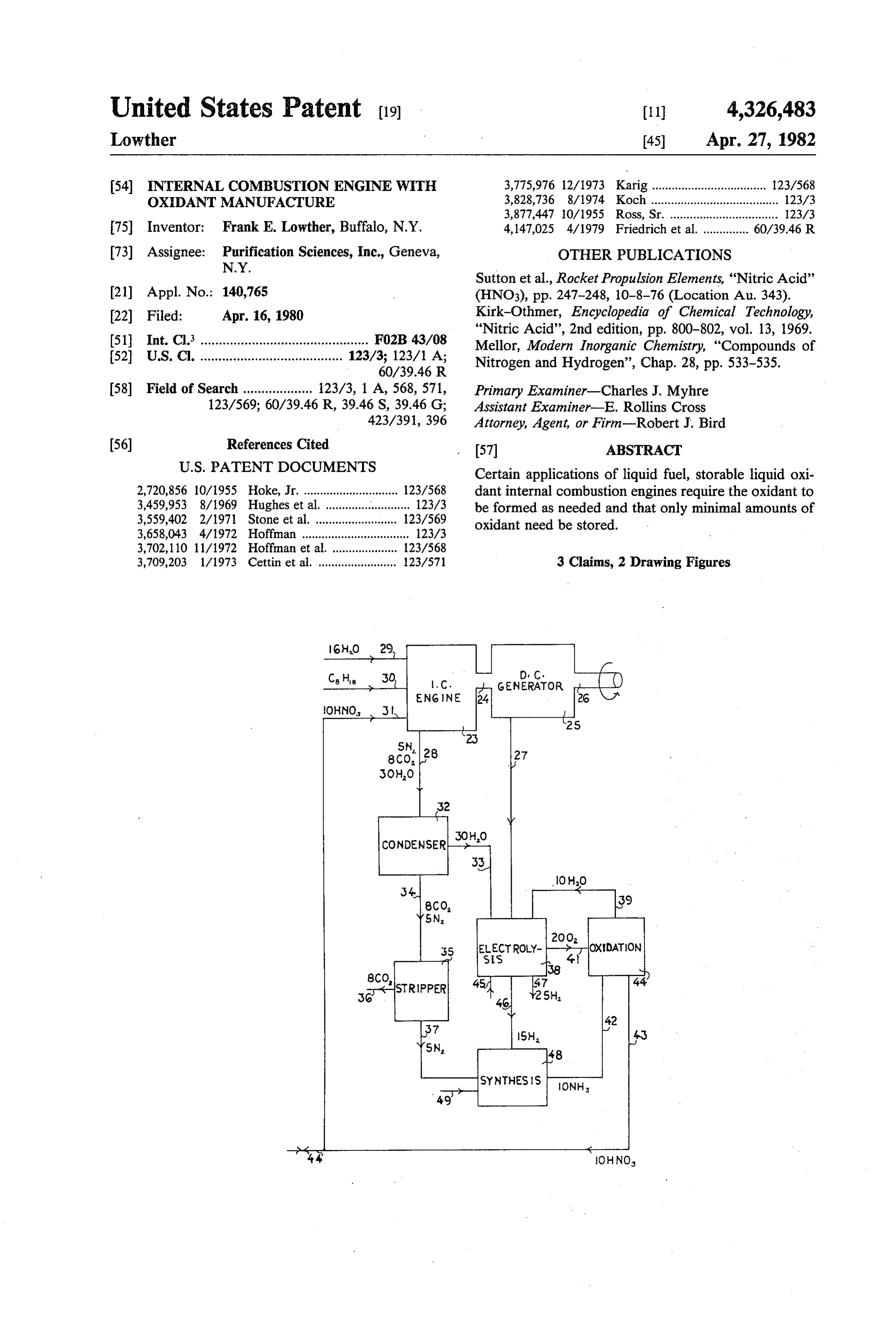
l. C. GENERATOR
ENG NE
Page 2
Drawing sheet — no readable text.
Page 3
Drawing sheet — no readable text.
Page 4
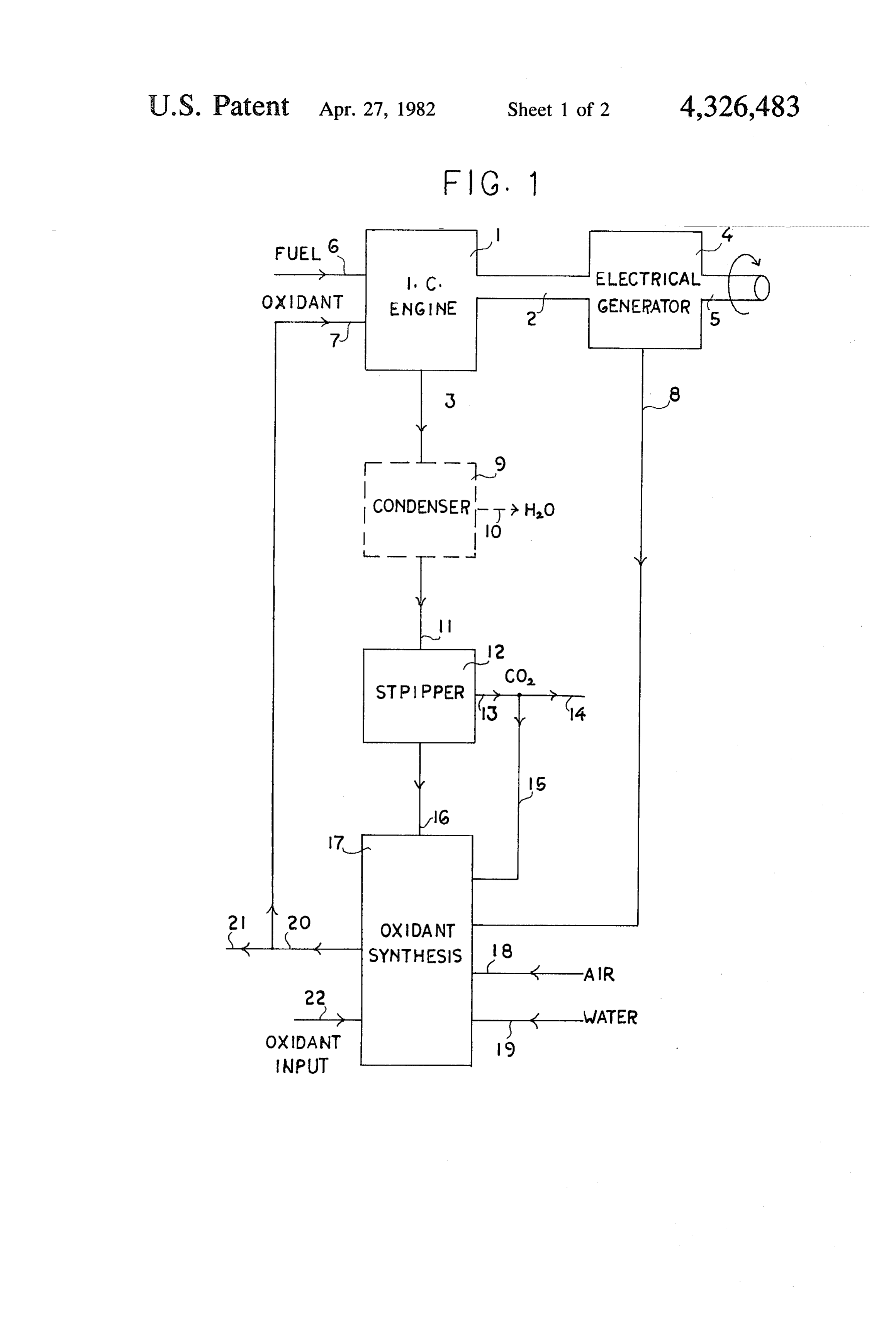
ate on liquid fuel 6 and liquid (storable at normal tem
INTERNAL COMBUSTION ENGINE WITH peratures) oxidant 7 and includes output shaft 2, 5 OXIDANT MANUFACTURE which drives electrical generator 4 inbetween. The
BACKGROUND OF THE INVENTION
output work shaft is shown as 5. The exhaust gases 3 from engine 1 pass through a condenser 9 that extracts
Certain advantages exist for an internal combustion water through line 10. The condenser 9 is no more engine that uses a storable liquid oxidant in place of the elaborate than a water-driven heat exchanger that cools ambient atmosphere as a source of oxygen to combust the engine exhaust 3 to less than 212 F. Condenser 9 is the fuel. In such a case, two storage tanks are required, O shown as dotted, as in some applications it may be desir one for the fuel and one for the oxidant. The two stor able to keep the exhaust moisture in vapor form. The age tank requirement may be inconvenient in certain exhaust gases pass from condenser 9 to carbon dioxide applications, submarine service, for example. The pres stripper 12 via pipe 11. The carbon dioxide free exhaust ent invention includes methods and apparatus wherein gases pass from stripper 12 to oxidant synthesis unit 17 the liquid oxidant is formed locally from air, water, 15 via pipe 16. The carbon dioxide leaves stripper 12 via exhaust and energy. pipe 13 and a portion is wasted via pipe 14 and a portion Prior Art Description is passed to the oxidant synthesis unit 17 via pipe 15. Electricity from the generator 4 may be conducted for
Closed cycles in terms of exhaust products have been use in the oxidant synthesis unit 17 by electrical conduc proposed for gaseous oxidant internal combustion en tor 8. Ambient air 18 and water 19 may be used in oxi gines. U.S. Pat. No. 3,559,402, titled Closed Cycle Diesel 20 dant synthesis unit 17. A portion of water 19 may be Engine by W. J. Stone is an example. The engine is not condensed closed in terms of oxidant, since liquid oxygen is intro of oxidant water 10 out of condenser 9. A small amount manufactured elsewhere 22 may be needed duced from external sources and vaporized prior to for priming and/or starting purposes, and to assure a entry into the engine cylinder. A storage tank some smooth and continuous operation. The oxidant storage where is required to hold the liquid oxygen unless a 25 capacity cryogenic plant generates the liquid oxygen exactly as in oxidant synthesis unit 17 is small and is not needed (which seems unlikely), but this is not specified to be construed to be a main storage tank. Typically, as such. one gallon of oxidant may be stored in the oxidant syn Additional non-air breathing internal combustion thesis unit 17. The manufactured liquid oxidant leaves engines all appear to specify a tank to hold the oxygen 30 the synthesis unit 17 via pipe 20. A portion of the manu containing oxidant. Examples include the following factured oxidant enters engine 1 via pipe 7 and an excess U.S. Pat. NOS.: may be manufactured for other purposes and is tapped 2,720,856 Hoke; off at pipe 21.
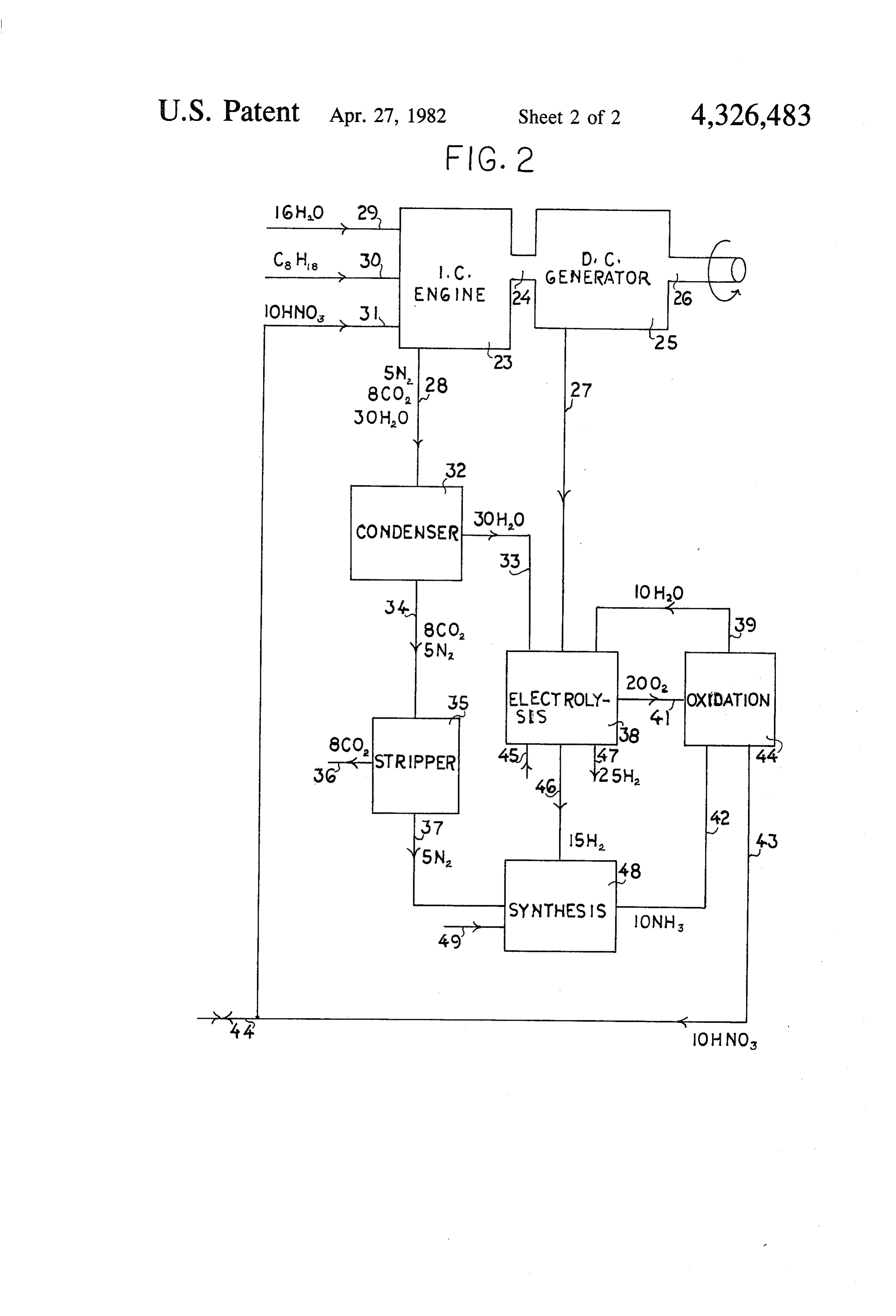
3,709,203 Cettin; FIG. 2 is a specific embodiment of the present inven 3,775,976 Karig 35 tion wherein the liquid oxidant manufactured is nitric 4,047,380 Heffernan; acid, HNO3. The accompanying chart presents the gov 4,091,769 Baldwin. erning mass balance equations. Auxiliary equipment SUMMARY OF THE INVENTION that will be required for starting and other usual house keeping functions is not shown in either FIG. 1 or FIG.
The present invention includes methods and appara 40 2. For example, the electrical generator in FIGS. 1 and tus wherein storable liquid oxidants for use in internal 2 may be used to maintain a charge in an electric battery combustion engines are manufactured locally, essen which, in turn, is keyed to drive a starting motor via the tially as needed. Small amounts may be stored for start ignition switch. Additionally, electric driven pumps ing periods and the like. powered by the starting battery may be used to move It is an object of this invention to require only the 45 around the various liquids, drive compressors for the storage of fuel and water for an internal combustion CO2 stripper, engine that uses a storable (non-cryogenic) liquid oxi considered toetc. be
These housekeeping functions are not essential in the understanding of the dant to combust the fuel.
It is another object of this invention to locally manu present invention.
facture the liquid oxidant from locally available raw 50 output Internal combustion engine 23 in FIG. 2 includes an materials: air, water, exhaust products from the engine, mechanical shaft 24 which drives electrical D.C. and energy. The energy may come from a stored source generator 25 which, in turn, includes an output shaft 26 such as an electric battery, or may be generated by the from which is merely an extension of shaft 24. The exhaust 28. engine itself (i.e., a motor driven electric generator). engine 23 contains nitrogen, carbon dioxide, and These and other objects and features of the invention 55 water, all in the gaseous state. Condenser 32 condenses will be apparent to a skilled scientist by reference to the out water and feeds the same to an electrolysis unit 38 following description and drawings, via pipe 33. Water-free exhaust gases leave condenser 32 via pipe 34 and enter carbon dioxide stripper 35.
BRIEF DESCRIPTION OF THE DRAWINGS Carbon dioxide stripper 35 may be of any of the stan FIG. 1 illustrates, in diagramatic form, the principles 60 dard commercial types made possible by the high solu of the present invention. bility of carbon dioxide in water and/or the ease with FIG. 2 is a specific embodiment of the present inven which carbon dioxide may be solidified. In the present tion. invention, the removed carbon dioxide 36 is not used
DETAILED DESCRIPTION
and is shown as being wasted. In another embodiment, 65 it may be useful to utilize the carbon dioxide 36 as a
FIG. 1 is a part schematic and part functional dia coolant to the engine or as a dilutant in place of a por gram illustrating the basic concept of the present inven tion of the water 29 if said carbon dioxide 36 is available tion. Internal combustion engine 1 is structured to oper in solid (dry ice) form.
Page 5
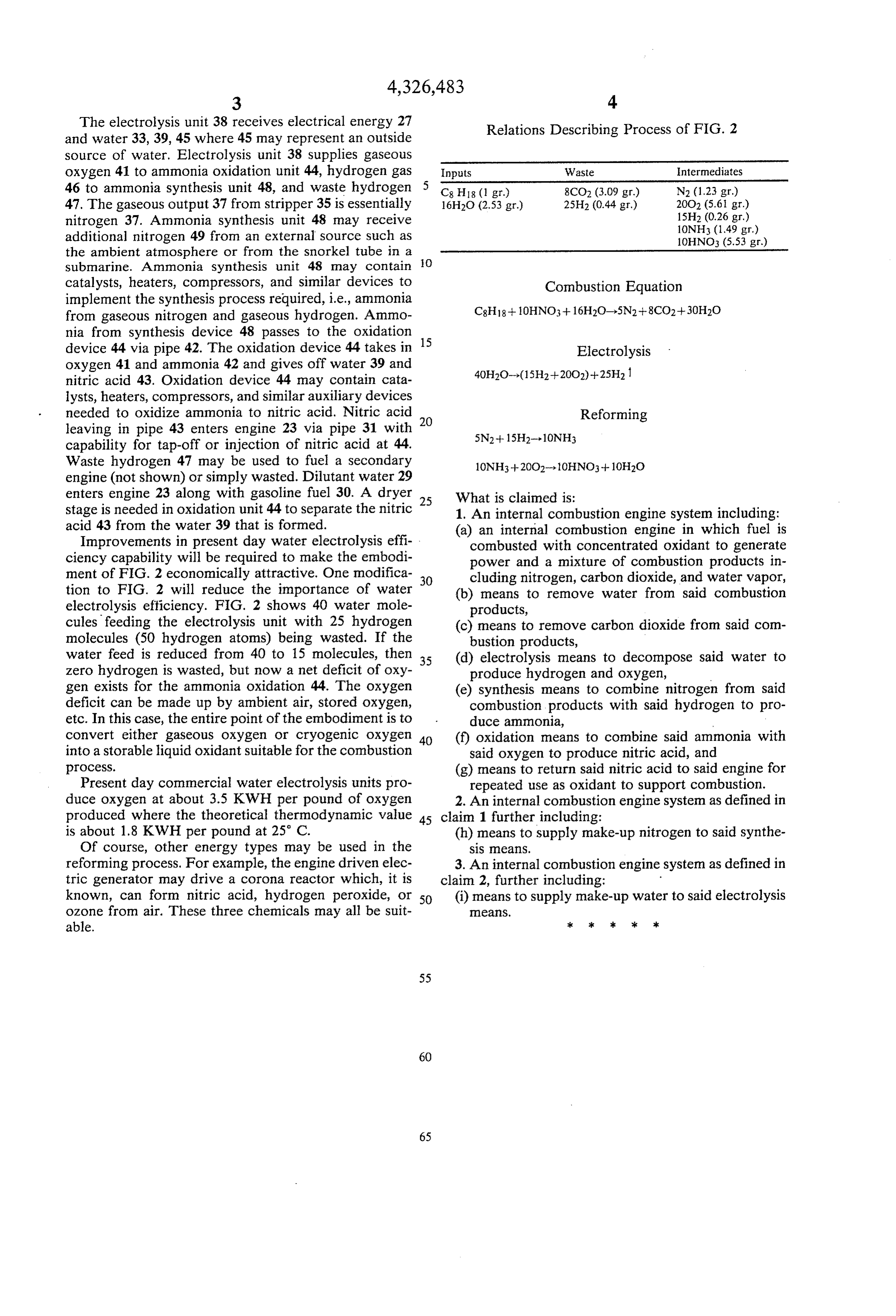
The electrolysis unit 38 receives electrical energy 27 Relations Describing Process of FIG. 2 and water 33, 39, 45 where 45 may represent an outside source of water. Electrolysis unit 38 supplies gaseous oxygen 41 to ammonia oxidation unit 44, hydrogen gas Inputs Waste Intermediates 46 to ammonia synthesis unit 48, and waste hydrogen 5 C8H18 (1 gr.) 8CO2 (3.09 gr.) N2 (1.23 gr.) 47. The gaseous output 37 from stripper 35 is essentially 16H2O (2.53 gr.) 25H2 (0.44 gr.) 20O2 (5.6 gr.) nitrogen 37. Ammonia synthesis unit 48 may receive 15H2 (0.26 gr.)
additional nitrogen 49 from an external source such as 10HNO3 (5.53 gr.) the ambient atmosphere or from the snorkel tube in a O submarine. Ammonia synthesis unit 48 may contain catalysts, heaters, compressors, and similar devices to Combustion Equation implement the synthesis process required, i.e., ammonia from gaseous nitrogen and gaseous hydrogen. Ammo C8H18-- OHNO3 + 16H2O-5N2 --8CO2+30H2O nia from synthesis device 48 passes to the oxidation device 44 via pipe 42. The oxidation device 44 takes in 15 Electrolysis oxygen 41 and ammonia 42 and gives off water 39 and 40H2O-(15H2--20O2)+25H2 nitric acid 43. Oxidation device 44 may contain cata lysts, heaters, compressors, and similar auxiliary devices needed to oxidize ammonia to nitric acid. Nitric acid Reforming leaving in pipe 43 enters engine 23 via pipe 31 with 20 5N2 + 15H2--10NH3 capability for tap-off or injection of nitric acid at 44.
Waste hydrogen 47 may be used to fuel a secondary engine (not shown) or simply wasted. Dilutant water 29 enters engine 23 along with gasoline fuel 30. A dryer What is claimed is:
stage is needed in oxidation unit 44 to separate the nitric 25 1. An internal combustion engine system including: acid 43 from the water 39 that is formed. (a) an internal combustion engine in which fuel is Improvements in present day water electrolysis effi combusted with concentrated oxidant to generate ciency capability will be required to make the embodi power and a mixture of combustion products in ment of FIG. 2 economically attractive. One modifica 30 cluding nitrogen, carbon dioxide, and water vapor, tion to FIG. 2 will reduce the importance of water (b) means to remove water from said combustion electrolysis efficiency. FIG. 2 shows 40 water mole products, cules feeding the electrolysis unit with 25 hydrogen (c) means to remove carbon dioxide from said com molecules (50 hydrogen atoms) being wasted. If the bustion products, water feed is reduced from 40 to 15 molecules, then 35 (d) electrolysis means to decompose said water to Zero hydrogen is wasted, but now a net deficit of oxy produce hydrogen and oxygen, gen exists for the ammonia oxidation 44. The oxygen (e) synthesis means to combine nitrogen from said deficit can be made up by ambient air, stored oxygen, combustion products with said hydrogen to pro etc. In this case, the entire point of the embodiment is to duce ammonia, convert either gaseous oxygen or cryogenic oxygen 40 (f) oxidation means to combine said ammonia with into a storable liquid oxidant suitable for the combustion said oxygen to produce nitric acid, and process. (g) means to return said nitric acid to said engine for Present day commercial water electrolysis units pro repeated use as oxidant to support combustion. duce oxygen at about 3.5 KWH per pound of oxygen 2. An internal combustion engine system as defined in produced where the theoretical thermodynamic value 45 claim 1 further including:
is about 1.8 KWH per pound at 25° C. (h) means to supply make-up nitrogen to said synthe Of course, other energy types may be used in the sis means.
reforming process. For example, the engine driven elec 3. An internal combustion engine system as defined in tric generator may drive a corona reactor which, it is claim 2, further including: known, can form nitric acid, hydrogen peroxide, or 50 (i) means to supply make-up water to said electrolysis ozone from air. These three chemicals may all be suit leaS.
able. x k is is k
Provenance
- Collection
- Cited prior art
- Original PDF
- patentimages.storage.googleapis.com →
- Filed
- 1980-04-16
- Pages
- 5
- Method
- pdftotext (the PDF's own text layer) + pdftoppm 300dpi page scans
- Source
- Google Patents bibliographic record
- Granted
- 1982-04-27
- Inventors
- Frank E. Lowther; Purification Sciences Inc
- Transcribed from
- patentimages.storage.googleapis.com →