patent · US4319560A
Solar heating system
16 March 1982
Page 1 — bibliographic record
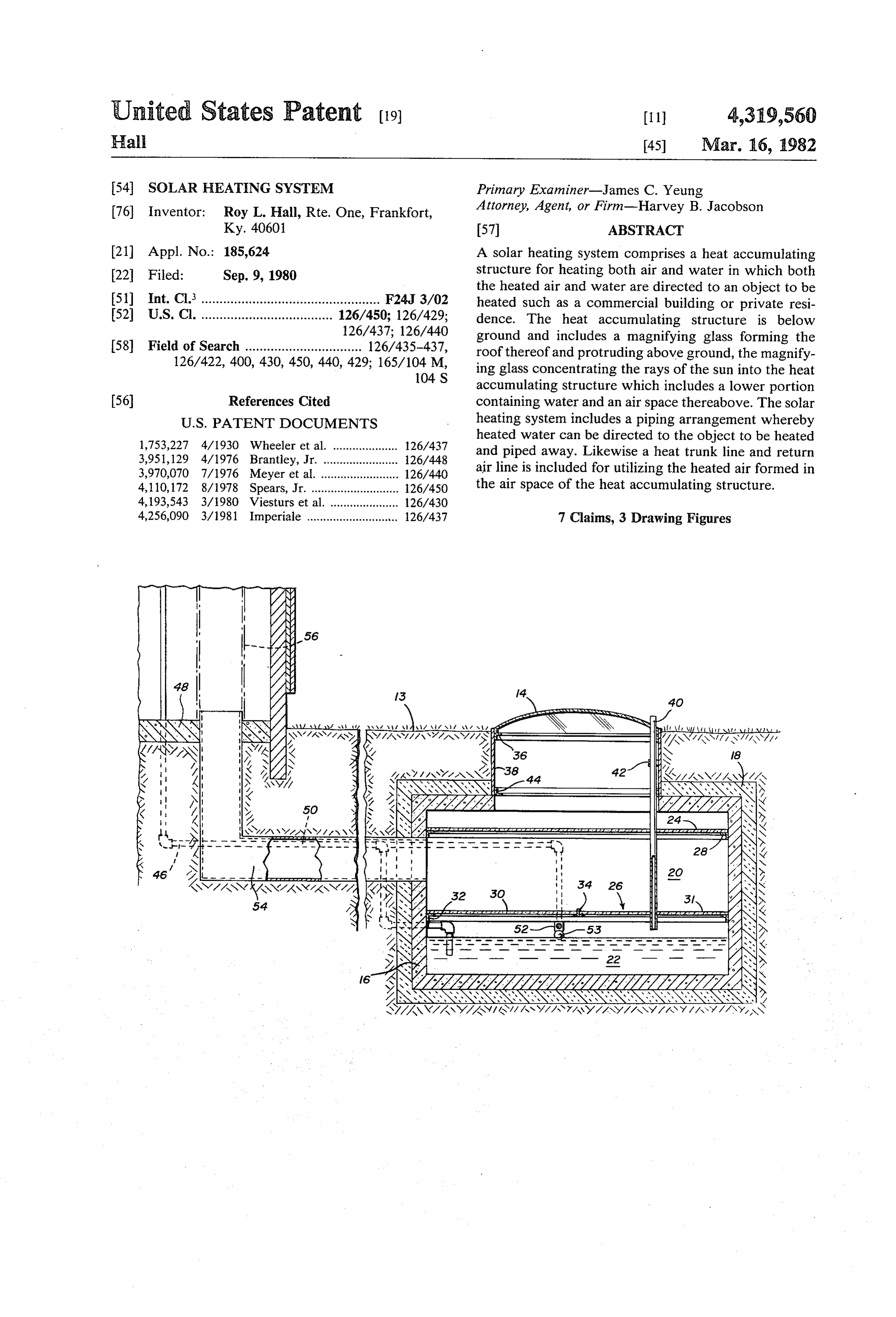
United States Patent (19) (11) 4,319,560 Hall 45) Mar. 16, 1982 54). SOLAR HEATING SYSTEM Primary Examiner-James C. Yeung 76 Inventor: Roy L. Hall, Rte. One, Frankfort, Attorney, Agent, or Firm-Harvey B. Jacobson Ky. 40601 57 ABSTRACT 21 Appl. No.: 185,624 A solar heating system comprises a heat accumulating 22 Filed: Sep. 9, 1980 structure for heating both air and water in which both the heated air and water are directed to an object to be 51) int. Cl. ................................................. F24J 3/02 heated such as a commercial building or private resi 52 U.S. Cl. .................................... 126/450; 126/429; dence. The heat accumulating structure is below 126/437; 126/440 ground and includes a magnifying glass forming the 58) Field of Search ................................ 126/435-437, roof thereof and protruding above ground, the magnify 126/422, 400, 430, 450, 440, 429; 165/104 M, ing glass concentrating the rays of the sun into the heat
accumulating structure which includes a lower portion 56) References Cited containing water and an air space thereabove. The solar
heated water can be directed to the object to be heated 3,951,129 4/1976 Brantley, Jr. .... ... 126/448 and piped away. Likewise a heat trunk line and return 3,970,070 7/1976 Meyer et al......................... 126/440 air line is included for utilizing the heated air formed in 4,110, 172 8/1978 Spears, Jr. ........................... 126/450 the air space of the heat accumulating structure. 4,193,543 3/1980 Viesturs et al ... 126/430 4,256,090 3/1981 Imperiale ........................... 126/437 7 Claims, 3 Drawing Figures
Z/ aSY 7/NY-N4. Q
V7, 2.
Page 2
Drawing sheet — no readable text.
Page 3
Drawing sheet — no readable text.
Page 4
heated air and water to a building structure and which
SOLAR HEATING SYSTEM can be built at minimum expense.
Still another object of the present invention is to
FIELD OF THE INVENTION provide a solar heating system for heating and storing This invention relates to a solar heating system. More both air and water in a single storage facility and which particularly, the invention relates to a system for heat is able to supply the heated air and water to a building. ing both air and water in a heat accumulating structure Still yet another object of the invention is to provide which is situated below ground level and which is able a solar heating system adjacent a building to provide to store the heated air and water for use when desired. heated air and water thereto in which a storage tank for Recently, there has been great interest in utilizing O heating and storing the heated air and water is below solar energy as an alternative for finite fossil fuel re ground.
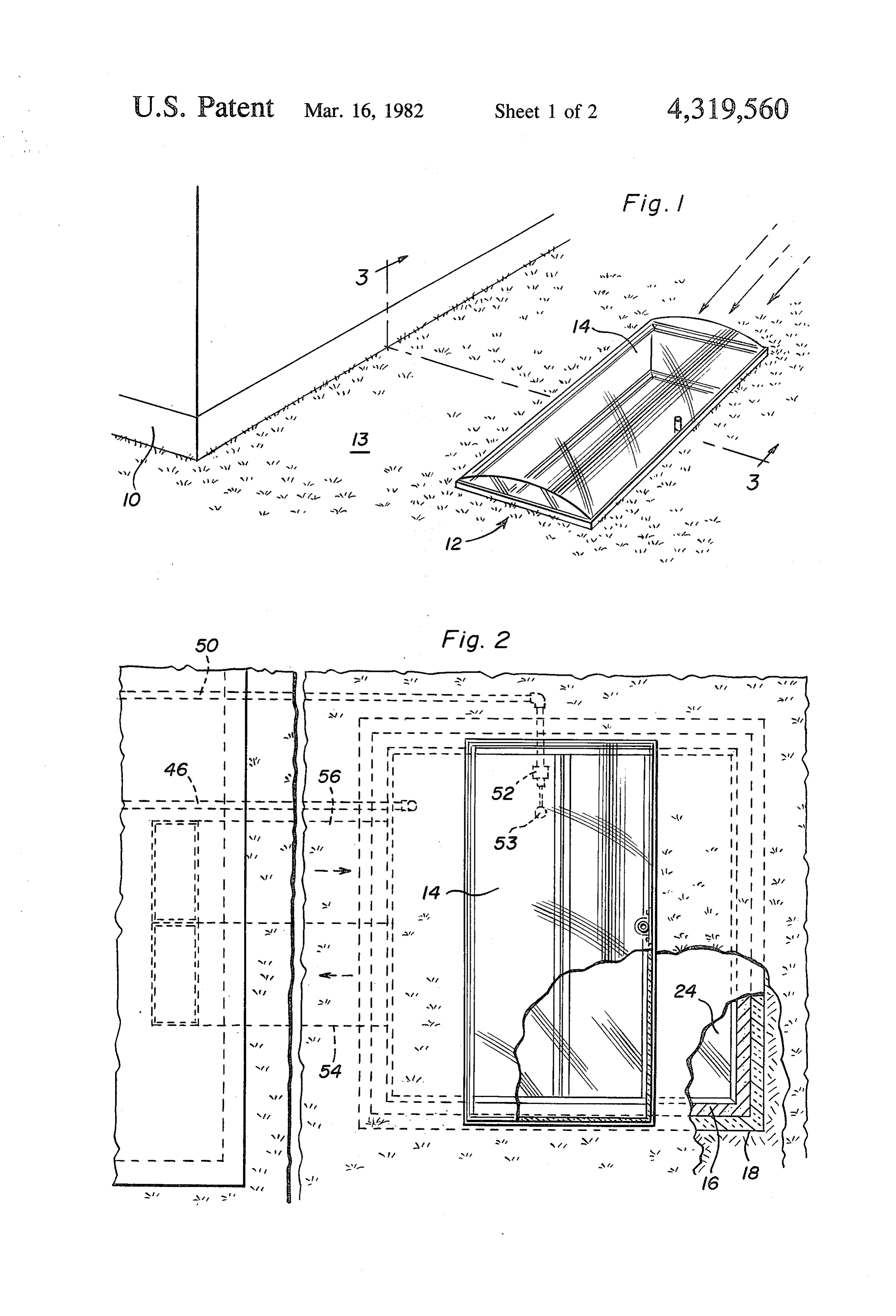
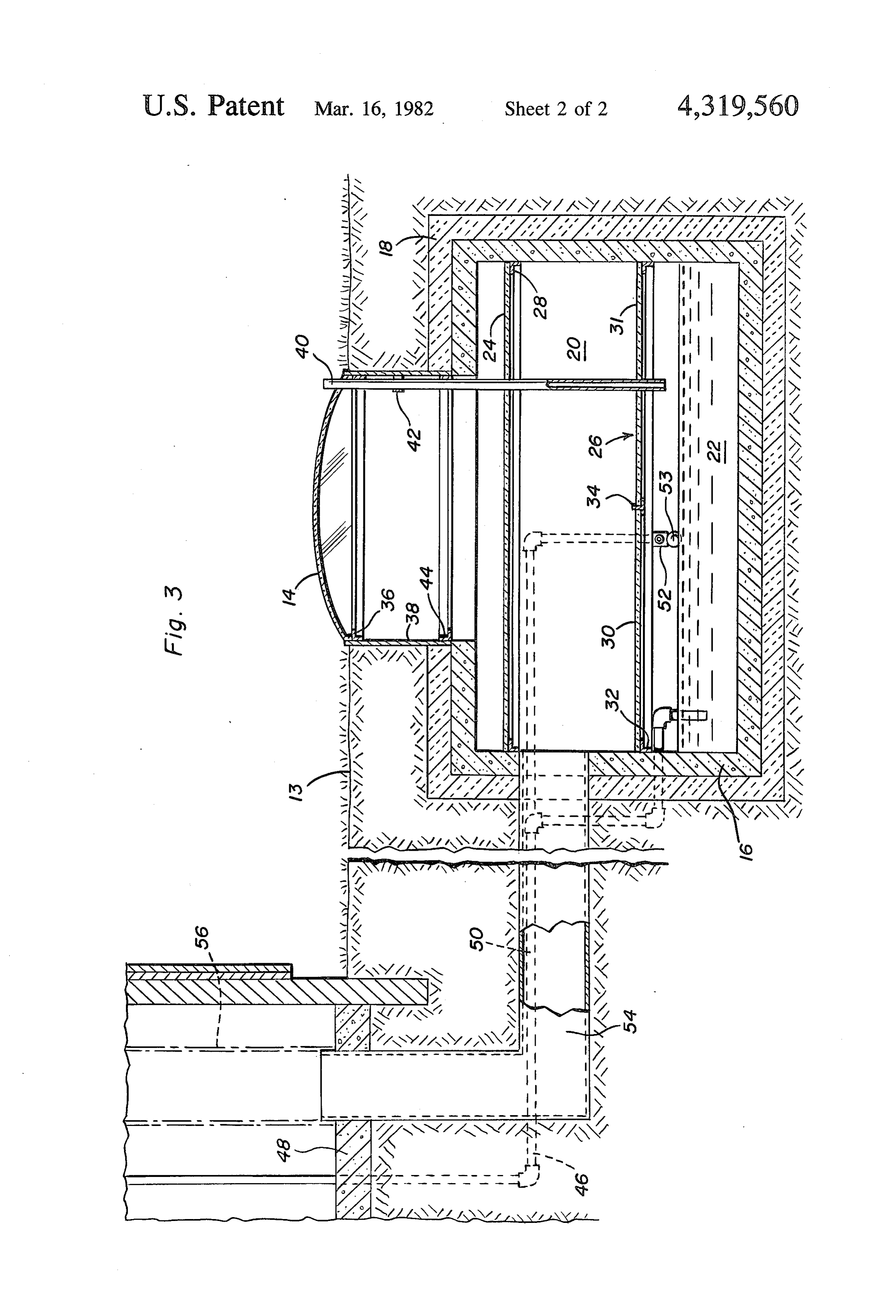
Sources. Many systems have been designed for heating These together with other objects and advantages air or water by direct radiation from the sun directed on which will become subsequently apparent reside in the a single or a plurality of solar collectors placed on the 15 details of construction and operation as more fully here roof of a commercial building or private residence. inafter described and claimed, reference being had to Many patents have been issued on various configura the accompanying drawings forming a part hereof, tions of solar collectors. Such solar heating systems wherein like numerals refer to like parts throughout. have found use in heating air or water for space heating BRIEF DESCRIPTION OF THE DRAWINGS purposes and for hot water usage in general. While recent energy shortages and rising energy costs have 20 FIG. 1 is a perspective view illustrating the place brought on the increased interest in solar heating, solar ment of the solar heat system of the present invention heating systems utilizing industrial age technology have adjacent a building in which the solar heating and stor been designed at the beginning of the twentieth century age tank is situated below ground and only the solar and beyond. An example of such a solar heating system energy concentrating device is above ground level. is disclosed in U.S. Pat. No. 965,391, issued July 26, 25 FIG. 2 is a top plan view of the solar heating system 1910 to Little in which an insulating receptacle is used of the present invention in which a portion of the heat to hold a mass of heat-absorbing bodies onto which the collecting
Sun's rays are concentrated by the use of a plurality of in section. and storage tank is broken away and shown lenses. The insulating receptacle includes a cold air inlet in contact with the heated bodies and a heated air outlet 30 FIG. 3 is a sectional view of the solar heating system in which heated air is directed to a building structure. of the present invention adjacent a building which re ceives the heated air and water from the heat collection
Other solar heat storage systems are disclosed in U.S. and storage tank taken generally along line 3-3 of FIG. Pat. No. 3,369,541, issued to Thomason, U.S. Pat. No. .
issued to Brussels. Each of these systems require a sepa 35 DETAILED DESCRIPTION OF THE rate solar heat collecting device in which air or water is INVENTION heated and directed to the storage chamber. Only the patent to Thomason discloses heating both air and wa In FIG. It is shown building 10 which receives heated ter. U.S. Pat. No. 2,167,576, issued to Kaiser discloses a air and water from solar heating system 12 of the pres Solar heating system for water while U.S. Pat. No. 40 ent invention. As can be seen in FIG. 1, only the solar 4,112,920, issued to Hillman discloses a solar heating energy concentrating means such as rectangular magni system for liquid or air. In each case, the heated water fying glass 14 is above ground and as close to building or air can be separately stored. U.S. Pat. Nos. 4,003,363 10 as possible to reduce pumping and piping costs. The and 4,003,365 discloses solar heating panels. solar heating system 12 of the present invention does The solar heating system of the present invention is 45 not require an unsightly structure situated above able to heat and store both water and air in the same ground or placed on the roof of building 10 which can vessel without the need of separate solar heat collectors, adversely affect the landscape adjacent building 10, thus greatly reducing the cost of such systems. possibly reducing land values and can adversely affect the original architecture and reduce the value of build
SUMMARY OF THE INVENTION 50 ing 10, especially if building 10 is a private residence. Briefly, the solar heating system of the present inven Both water and air are heated and stored in the storage tion comprises an underground solar heat collecting and tank below ground in which solar radiation impinging storage tank containing an upper air storage compart upon magnifying glass 4, as indicated by the arrows, is ment and a lower water storage compartment. A solar concentrated and directed to the air and water con energy concentrator such as a relatively large magnify 55 tained in the storage tank below as more fully described ing glass is situated above ground to direct and concen below.
trate the rays of the sun into the solar heat storage tank. Referring to FIGS. 2 and 3, solar heating system 12 The solar heat collecting and storage tank is preferably includes magnifying glass 14 to concentrate and direct situated adjacent a commercial building or private resi solar radiation to heat collecting and storage tank 16 dence and is used to supply heated air and water 60 which is placed below ground level and out of sight of thereto, the storage tank including a return for the air landscaping 13. Tank 16 is preferably formed of con and water from the building for reheating of the re crete or fiber glass four inches thick and is surrounded turned air and water in their respective compartments. by a thermal insulation layer 18 such as a foamed poly It is an object of the present invention to provide a styrene insulation also about four inches thick. Storage solar heating system which allows for the simultaneous 65 tank 16 is divided into two compartments, air storage heating and storing of both air and water. compartment 20 and water storage compartment 22. Another object of the present invention is to provide Compartments 20 and 22 are covered with glass baffles a solar heating system which is capable of supplying 24 and 26, respectively. Glass baffle 24 is supported by
Page 5
means of aluminum flange 28 placed about the full pe of air. A space six inches above glass baffle 24 is left rimeter of storage tank 16. Glass baffle 26 formed in two between the inside surface of storage tank 16 and glass sections 30 and 31 is supported by aluminum flange 32 baffle 24. Magnifying glass 14 has a width of about four placed along the perimeter of tank 16 and flange 34 a feet placed at the center of storage tank 16 and a length T-shaped flange placed across the center of tank 16. 5 of about eight feet across the top of storage tank 16. Each of the aluminum flanges is secured to the inner Magnifying glass 14 is spaced about one and one-half surface of storage tank 16 by means of an adhesive, feet from the top of storage tank 16 by means of steel bolts, or any suitable attaching means. As can be seen in support structure 38. Aluminum flanges 28 and 32 com FIG. 3, glass baffles 24 and 26 rest upon the perimeter prise L-shaped members in which each leg of the flange shelf formed by aluminum flanges, 28 and 32, respec including shelves 29 and 30 is one inch. Aluminum tively, sections 30 and 31 also resting on the shelf 10 flanges 36 and 44 are similarly one inch by one inch long formed by flange 34. Glass baffle 24 need not be a single with respect to the length of each leg of the L-shaped glass sheet, but can be formed from a plurality of nar flange. T-shaped flange 34 also includes one inch row glass sections. Likewise, glass baffle 26 can also be shelves 35 and 37. Magnifying glass 14 is preferably just formed from a plurality of glass strips. Solar radiation above ground level as illustrated in FIG.1. Glass baffles impinged upon magnifying glass 14 is concentrated and 15 24 and 26 can be single sheets of glass or be divided into directed through glass baffle 24 to air storage compart two, three or even four portions to cover substantially ment 20 and through glass baffle 26 to water storage the total area of air storage portion 20 and water storage compartment 22. portion 22.
Lens 14 is supported by aluminum flange 36 which The foregoing is considered as illustrative only of the supports the full perimeter of magnifying lens 14 and is 20 principles of the invention. Further, since numerous secured to rectangular steel frame structure 38. Conduit modifications and changes will readily occur to those vent 40 vents expanding air from water storage com skilled in the art, it is not desired to limit the invention partment 22 to the atmosphere. Vent 40 is secured to to the exact construction solar heat system 12 by means of a clamp 42 secured to described, and accordingly,and operation shown and all suitable modifications steel support structure 38. A second perimeter alumi 25 and equivalents may be resorted to, falling within the num flange 44 is attached to steel structure 38 for scope of the invention.
strength and is available for supporting a separate solar What is claimed as new is as follows: radiation concentrating lens, if desired. 1. A solar heating system for supplying heated air and Water stored in water storage portion 22 and heated by solar radiation directed by magnifying lens 14 is water for use in a building, said system comprising an pumped into building 10 via waterline 46 such as a 30 enclosed storage tank positioned below ground level, a three-quarter inch copper tubing. Waterline 46 can be tion to saidglass magnifying to direct and concentrate solar radia inserted through basement floor 48 or a crawl space at above groundstorage tank positioned adjacent to and about ground level. Water heated in water storage por storage portionlevel, said storage tank comprising an air fully below ground level and a water tion 22 of solar heating system 12 is heated to a tempera storage portion below ture sufficient for use in a manner associated with com- 35 storage portion and saidsaid air storage portion, said air water storage portion compris mercial or private residential buildings. Hot water ing hollow regions formed by said storage tank and which has been used is piped away as waste water. A containing the respective fluids, said water storage por standard pipe cut-off valve 52 and ball float 53 accu tion comprising an inlet and an outlet communicating rately control the water level in water storage portion 22 which is supplied via piping 50. with the interior of said building for circulation and use A heated air trunk line 54 communicates with air 40 of heated water in said building and said air storage storage portion 20 and is connected to a conventional portion comprising an inlet and outlet communicating ducting system 56 in building 10. Trunk line 54 like with the interior of said building for circulation and use water line 46 is directed through the basement floor 48 of heated air, said water storage portion being separated or a crawl space of building 10. Placed adjacent heated from said air storage portion by means of a transparent air trunkline 54 is return air duct 56 which returns air to 45 baffle, said magnifying glass being separated from said air storage portion 20. The direction of arrows in ducts air storage portion by a transparent baffle, and said 54 and 56 indicates the movement of air to and from storage tank being covered substantially with a thermal solar heating system 12. A blower (not shown) placed in insulating layer.
the conventional ducting system in building 10 provides 2. The system of claim 1 wherein said transparent for the required air movement. 50 baffles are made of glass.
While the dimensions of solar heating system 12 may 3. The system of claim 2 wherein said baffles are vary considerably depending upon use and location, the positioned within said storage tank by means of alumi following dimensions can be used as a guide to provide num flange supports which are secured to the inner solar heated air and water to a commercial building or surface of said tank and include a shelf member upon private residence. Storage tank 16 comprising a four 55 which said baffles are seated.
inch thick concrete or fiber glass shell has an outside 4. The system of claim 1 wherein said magnifying dimension of eight foot square and an inside height of glass covers an area smaller than the area of the top of four feet. Surrounding shell 16 is four inches of insula said storage tank.
tion 18 such as "styrofoam' insulation. As can be seen in 5. The system of claim 1 wherein said water inlet FIG. 3, insulation 18 is placed along the total perimeter 60 includes a cut-off valve and means to operate said valve of storage tank 16 and top and bottom thereof. The by sensing the level of water in said water storage por water level in water storage portion 22 is maintained at tion.
about twelve inches from the bottom of storage tank 16 6. The system of claim 1 wherein said water storage which is equal to a storage capacity of about 1,000 portion includes a conduit vent positioned within said gallons of water. Preferably six inches of space is left water storage portion and communicating with the between the water level in water storage portion 22 and 65 atmosphere above ground level.
the bottom of glass baffle 26. Air storage portion 20 has 7. The system of claim 1 wherein said storage tank is a height of about two feet between glass baffles 24 and formed of concrete ork fiber glass. 26 providing a storage capacity of about 128 cubic feet ck k sk sk
Provenance
- Collection
- Patents citing this work
- Pages
- 5
- Method
- pdftotext (the PDF's own text layer) + pdftoppm 300dpi page scans
- Patent office record
- patents.google.com →
- Source
- Google Patents citing-documents table
- Assignee
- Hall Roy L
- Inventors
- Roy L. Hall
- Published
- 1982-03-16
- Transcribed from
- patentimages.storage.googleapis.com →