patent · US2167576
Solar heater
25 July 1939
Page 1
Drawing sheet — no readable text.
Page 2
Drawing sheet — no readable text.
Page 3
Patented July 25, 1939 2,167,576
UNITED STATES PATENT OFFICE
SOLAR HEATER,
Fred M. Kiser, Los Angeles, Calif.
Application August 25, 1937, Serial No. 160,907
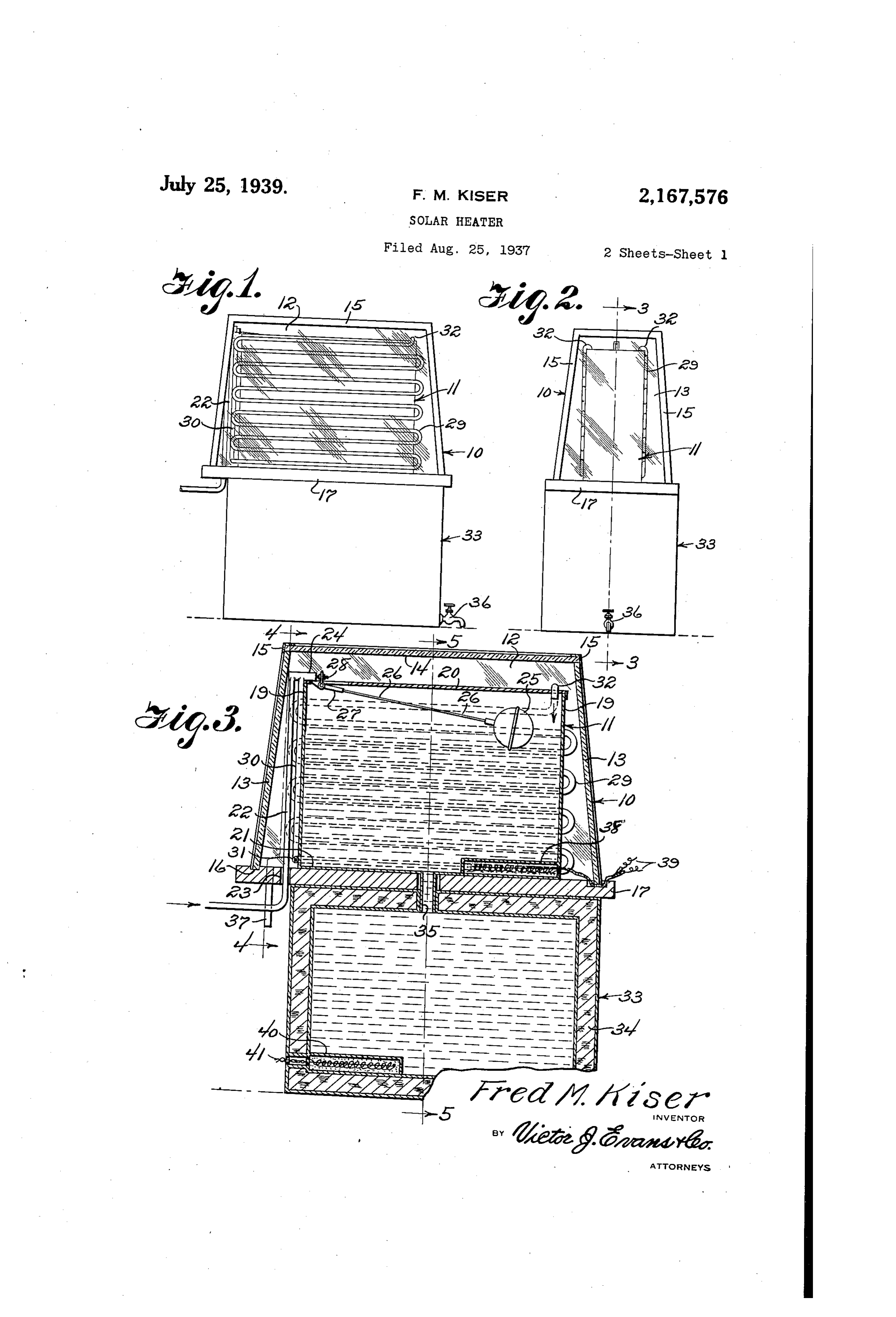
This invention relates to solar heaters and has hood is determined by the hot water require for an object to provide a self-contained solar ments and the hood preferably comprises up heater and storage tank wherein the water is Wardly inclined glass side walls 2, glass end walls maintained at a predetermined temperature, 3 and a glass top wall 14, the walls being con electrical heating means being provided when nected together and reinformed at their inter s the Sun is not shining or when the quantity of sections by angle iron strips 5. The bottom of heated water being drawn from the system ex the hood is open and fitS air tight in a groove ceeds the quantity of water being heated by the 6, formed in a supporting base fl, best shown Sun's rays. in Figure 6.
O A further object is to provide apparatus of
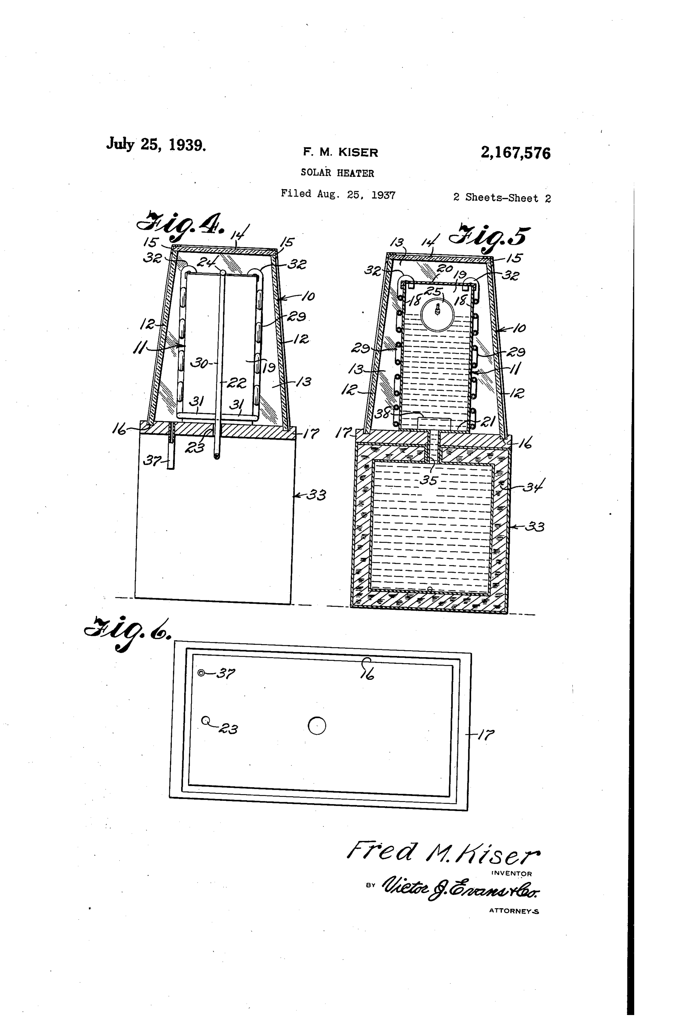
The water heating tank f is substantially 10 this type in which the Supply of water is auto rectangular in Contour and may be formed of any natically controlled so that a predetermined heat absorbing material such as copper for ex Water level Will always exist in the water heat ample, and constitutes a hot Water container. ing tank. The tank includes side walls 8, end walls 9, 5 A further object is to provide apparatus of and top and bottom walls 20 and 2, best shown 15 in Figures 3 and 5. A Water supply pipe 22, this type in which the glass hood, and the water best shown in Figures 3 and 4, and preferably heating tank, are superposed upon an insulated
Storage tank, the heated water flowing by grav connected to the city Water Supply System, ex ity into the storage tank so that the storage tends upwardly through an opening 23 dis posed near one end of the supporting base 7 20 20 tank Will always remain full to supply any num and above the top Wall of the Water heating ber of Spigots, the entire assembly being port tank is equipped with a cut off valve 24, best able, and being Self-contained. shown in Figure 3. The valve is automatically A further object is to provide apparatus of this controlled by a float 25, having its stem 26 con character which will be formed of a few strong nected to a bell crank 27 which is connected to 25 25 simple and durable parts, which will be inex the valve stem 28.
pensive to manufacture, and which will not The water heating tank forms a support for easily get out of order. heater coils 29 preferably arranged to extend With the above and other objects in view the longitudinally along the opposite sides of the invention consists of certain novel details of water heating tank as best shown in Figures 1, 30 30 construction and combinations of parts herein 3, 4 and 5. A Supply pipe 30 extends from the after fully described and claimed, it being un valve 24 and is provided at the bottom With lat derstood that various modifications may be re eral branch pipes 3, best shown in Figure 4, SOrted to Within the Scope of the appended claims
Without departing from the spirit or sacrificing which are connected to the bottom run of respec tive ones of the coils 29. The top runs of the coils 35 35 any of the advantages of the invention. are respectively equipped With hook-like dis In the accompanying drawings forming part of this specification, charge spouts 32, best shown in Figure 5, which Figure 1 is a side elevation of a solar heater hook over the top wall 9 of the water heating constructed in accordance with the invention. tank and extend into the tank through slots Figure 2 is an end elevation of the Solar heater formed in the top Wall. 40 40 Water under pressure will thus flow through shown in Figure 1.
Figure 3 is a longitudinal sectional view of the pipes and into the tank until a predetermined the Solar heater drawn to an enlarged scale. Water level is reached in the tank whereupon the Figure 4 is a cross sectional view taken on the float 25 Will close the Valve. The Sun's rays strik 45 line 4-4 of Figure 3.
ing through the glass hood Will heat the coils 45
Figure 5 is a cross sectional view taken on 29 and the hot Water therein will flow through the line 5-5 of Figure 3. the Spouts 32 into the Water heating tank Figure 6 is a plan view of the hood and heater when the valve 24 is opened by lowering of the tank Supporting base shown in Figure 3. float 25, or when the Water level is lowered in the Referring now to the drawings in which like tank f, thus automatically maintaining a prede 50 characters of reference designate similar parts termined Water level by pressure. The coils are in the various views, 0 designates a cover or preferably formed of good heat conducting na hood formed of material adapted to concentrate terial such as copper.
the sun's rays upon the Water heating tank The supporting base 7 is supported upon the top of a double Walled hot Water storage tank 33 55 55 Within the hood. The size and shape of the
Page 4
which is preferably rectangular in contour. The lower edge of the hood, a Water heating tank Sup space between the Walls of the tank is filled With ported on the base Within the hood, a Water cork insulation 34 or other good insulating ma Supply pipe entering the tank, a float controlled terial. An outlet pipe 35 projects through the top valve in said pipe, Water heating coils disposed 5 Wall of the storage tank and through the Support exteriorly of the said tank and exposed to Sun ing base 7, and enters the bottom of the Water rayS passing through the hood, said Water heating heating tank . Hot Water from the Water heat coils being connected at one end to said pipe and ing tank may be let into the storage tank by at the opposite end projecting into the top of the opening a suitable Spigot 36 connected to the Water heating tank, an insulated storage tank 10 storage tank, as best shown in Figures 1 and 2, disposed underneath and supporting the insulat O or may be piped from the storage tank to any ing base, a draw off Spigot connected to the stor desired locality. age tank, and a pipe extending through said in A drain pipe 37 projects through the support Sulating base and opening into the bottom of the ing base outside of the Storage tank and enters Water heating tank and opening into the top of the bottom of the Space between the water heat the storage tank for permitting the contents of 15 ing tank and the hood 0 to drain off any over the Water heating tank being drawn off through flow from the Water heating tank. the storage tank.
An electric heater 38 is disposed in the botton 2. A Solar heater comprising a glass hood, a of the Water heating tank and may be connected Supporting base having a groove receiving the by circuit wires 39 to any source of electricity. lower edge of the hood, a Water heating tank Sup 20 A Suitable Switch of course is employed to close ported on the base Within the hood, a Water Sup the circuits through the coil from some remote ply pipe entering the tank, a float controlled valve point. A similar electric heater 40 is disposed in in Said pipe, Water heating coils disposed ex the botton of the storage tank and is connected teriorly Of the said tank and exposed to Sun rays 25 to a switch controlled suitable source of current paSSing through the hood, said water heating coils Supply by circuit Wires 4. These heaters are being connected at One end to said pipe and at turned on When Weather conditions are not suit the Opposite end projecting into the top of the able to heat the Water in the Water heating tank Water heating tank, an insulated storage tank and also Whenever the quantity of heated Waterdisposed underneath and supporting the insulat 30 drawn from the system exceeds the quantity of ing base, a pipe extending through said insulat 30 Water being heated by the Sun's rays. ing base and opening into the bottom of the From the above description it is thought thatWater heating tank and opening into the top of the construction and operation of the inventionthe Storage tank, a draw off spigot connected to will be fully understood without further explana the Storage tank and electrically operated heat 35 tion.
What is claimed is:
ing devices in Said Water heating tank and in
Said Storage tank.
1. A Solar heater comprising a glass hood, a FRED M. KISER, Supporting base having a groove receiving the
Provenance
- Collection
- Cited prior art
- Original PDF
- patentimages.storage.googleapis.com →
- Filed
- 1937-08-25
- Pages
- 4
- Method
- pdftotext (the PDF's own text layer) + pdftoppm 300dpi page scans
- Source
- Google Patents bibliographic record
- Granted
- 1939-07-25
- Inventors
- Fred M Kiser
- Transcribed from
- patentimages.storage.googleapis.com →