patent · US4193543
Solar heating system
18 March 1980
Page 1 — bibliographic record
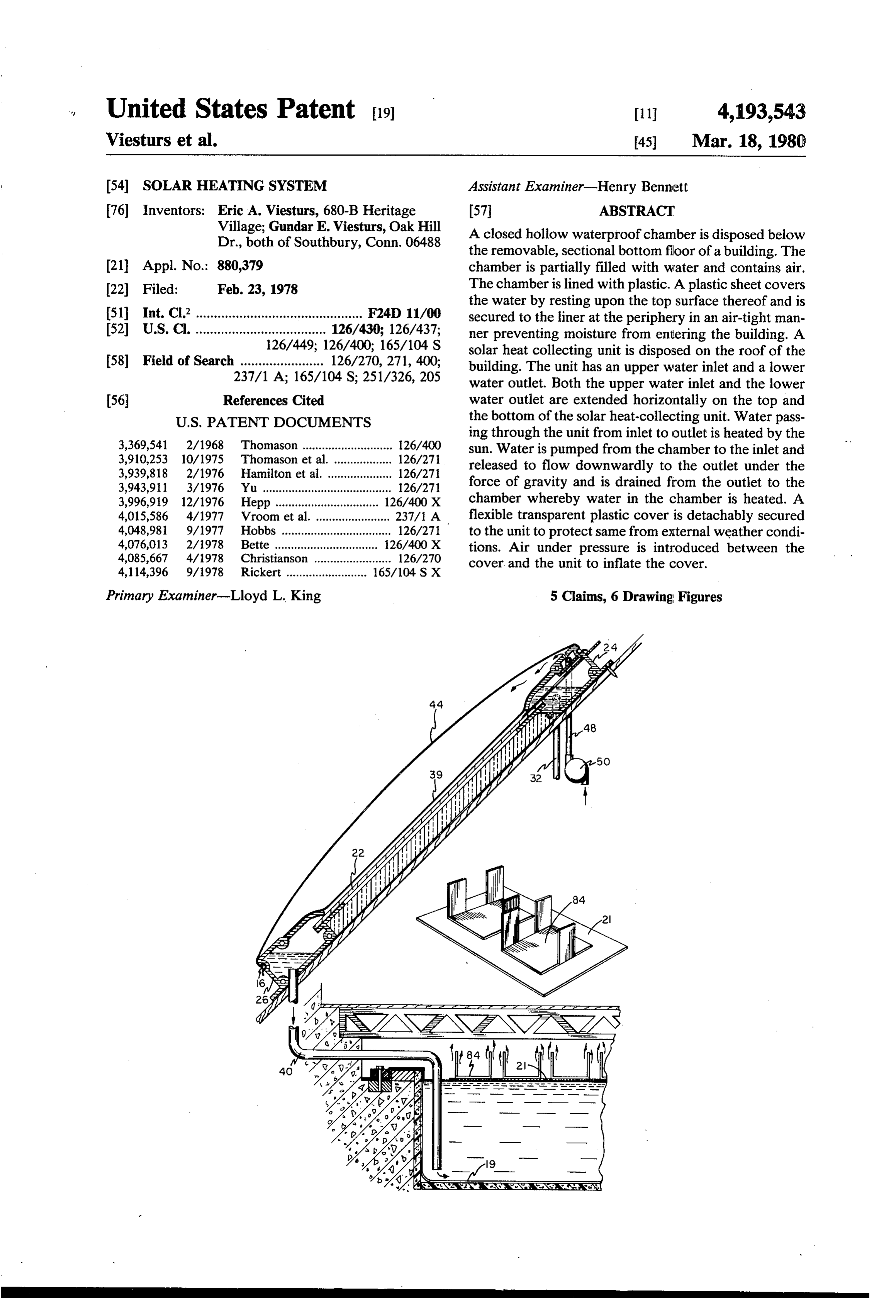
United States Patent (19) 11 4,193,543 Viesturs et al. 45) Mar. 18, 1980 (54) SOLAR HEATING SYSTEM Assistant Examiner-Henry Bennett 76) Inventors: Eric A. Viesturs, 680-B Heritage 57 ABSTRACT Village; Gundar E. Viesturs, Oak Hill A closed hollow waterproof chamber is disposed below Dr., both of Southbury, Conn. 06488 the removable, sectional bottom floor of a building. The 21 Appl. No.: 880,379 chamber is partially filled with water and contains air. 22 Filed: Feb. 23, 1978 The chamber is lined with plastic. A plastic sheet covers the water by resting upon the top surface thereof and is (51 Int. Cl’.............................................. F24D 11/00 secured to the liner at the periphery in an air-tight man 52 U.S.C. .................................... 126/430; 126/437; ner preventing moisture from entering the building. A 126/449; 126/400; 165/104 S solar heat collecting unit is disposed on the roof of the 58) Field of Search ....................... 126/270, 271, 400; building. The unit has an upper water inlet and a lower 237/1 A; 165/104 S; 251/326, 205 water outlet. Both the upper water inlet and the lower (56) References Cited water outlet are extended horizontally on the top and
ing through the unit from inlet to outlet is heated by the 3,369,541 2/1968 Thomason ............................ 26/400 sun. Water is pumped from the chamber to the inlet and 3,910,253 10/1975 Thomason et al. .................. 126/27 released to flow downwardly to the outlet under the 3,939,818 2/1976 Hamilton et al. . ... 126/27 3,943,911 3/1976 Yu ........................................ 126/271 force of gravity and is drained from the outlet to the 3,996,919 12/1976 Hepp .......... ... 126/400X chamber whereby water in the chamber is heated. A 4,015,586 4/1977 Vroom et al. ....................... 237/1 A flexible transparent plastic cover is detachably secured 4,048,981 9/1977 Hobbs .................................. 126/27 to the unit to protect same from external weather condi 4,076,013 2/1978 Bette .......... ... 126/400X tions. Air under pressure is introduced between the 4,085,667 4/1978 Christianson ........................ 126/270 cover and the unit to inflate the cover. 4,114,396 9/1978 Rickert ......................... 165/104 S X
Primary Examiner-Lloyd L. King 5 Claims, 6 Drawing Figures
Page 2
Drawing sheet — no readable text.
Page 3
Drawing sheet — no readable text.
Page 4
Drawing sheet — no readable text.
Page 5
Drawing sheet — no readable text.
Page 6
ened or embossed surface supported by heat insulating,
SOLAR HEATING SYSTEM rigid substrate. (Of course other good conductors of heat such as copper or other metals as well as high
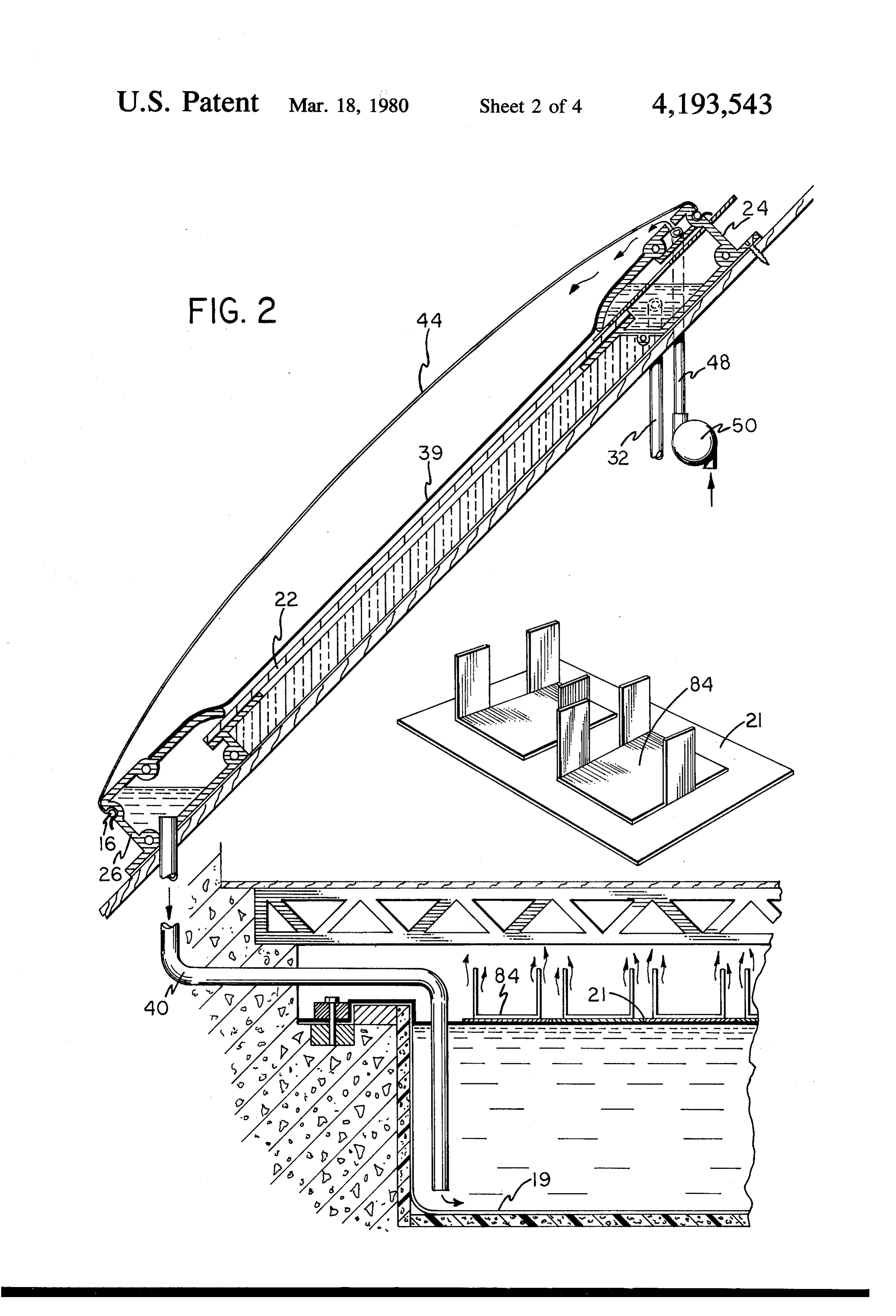
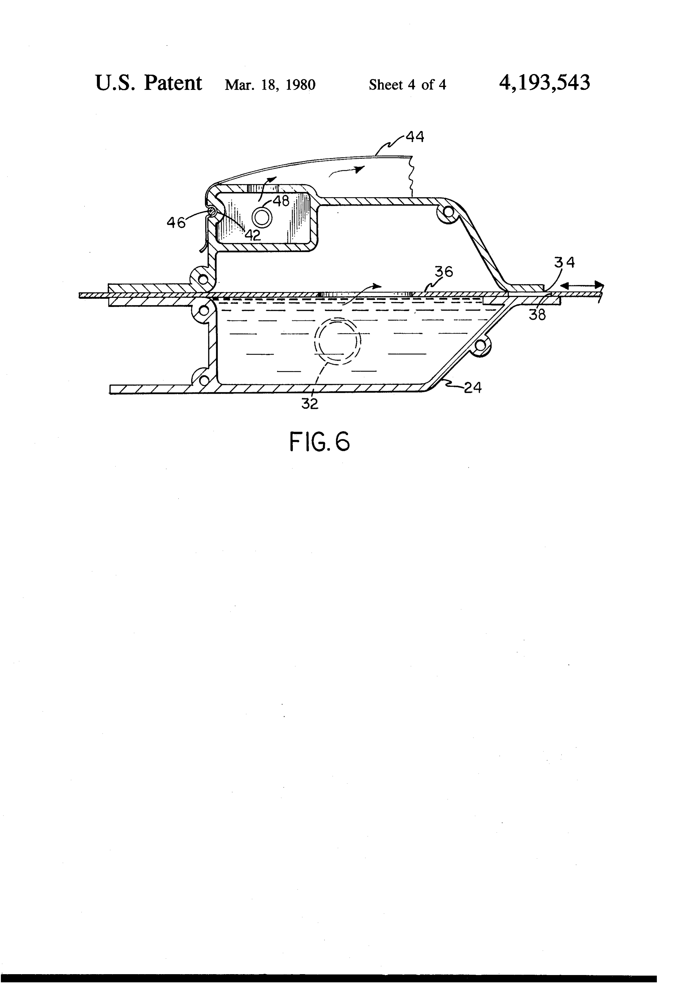
SUMMARY OF THE INVENTION temperature resistant plastic film can also be used). An This invention is directed toward a new type of solar 5 upper member 24, a lower member 26 and opposite side heating system wherein heat exchanger means transfers members 28 define a supporting rectangular frame for heat from a hot water source heated by solar energy to the plate, These members can be formed for example of air which is then used to heat the interior of a building extruded aluminum. The upper member 24 is hollow and wherein a roof mounted solar heat collecting unit is and water from the chamber is fed upward via an elec protected from external weather conditions by a pres 0 trically operated pump 30 and a vertical feed pipe 32 surized, easily replacable, inexpensive, transparent flexi into the interior of the member 24, Member 24 has an ble plastic cover, elongated horizontal opening 34 through which the To this end a closed waterproof hollow chamber water flows downwardly along the surface of the plate partially filled with water and containing air is disposed 22 and is collected into member 26 which defines a below the bottom floor of a building. Plastic sheet is 15 collector gutter. Plate 36, disposed in opening 34 is disposed at the interface of air and water, resting on the slidable back and forth in member 24 by manual action top surface of the water. Solar heat collecting means (this action can be automatically controlled if desired). mounted on the roof of the building has an upper water Plate 36 contains a plurality of triangularly shaped slots receiving inlet and a lower water discharge outlet. 38. The water discharged through opening 34 must first Water flowing through the heat collecting means from 20 pass through those portions of slots 38 which are made inlet to outlet is heated by solar energy.
An easily replaceable, flexible transparent cover is ward alongtoplate accessible the flows of water before flowing down 22. As the plate 36 is moved the area secured to the collector unit to protect same from exter of those portions can be increased between positions of nal weather conditions. The cover must be inflated to zero area in which water flow is blocked to intermedi perform this function and air under pressure is intro ate positions in which the rate of flow gradually in
duced between the cover and the unit to inflate the cover as needed, creased to a maximum position in which the entire area Water is pumped out of the chamber to the water This of slots 38 passes water and the rate of flow is maximum. inlet of the unit and is drained from the outlet of the unit adjustment controls the amount of water exposed back into the chamber whereby the water in the cham by solar regulates 30 and thus the temperature of the water heated energy while flowing along plate 22. The ber is heated.
Heat exchanger means disposed in the chamber is in roughened or embossed surface of the plate effectively contact with the heated water. Air is forced under pres lengthens the path of flow, increasing the period in sure into contact with the exchanger means and is which heat is transferred to the water so flowing and heated thereby. 35 hence increasing the amount of heat transferred. The The heated air is fed through suitable spaced outlets plate 22 is painted black to increase the heat collection in the building into the building interior and is circu efficiency of the solar heating unit. A strip of porous lated therein to heat the building interior. Thereafter below material such as felt or open cell foam can be disposed the circulated air is returned to the chamber to continue the slots 38 to distribute the released water more the heating process. evenly over the entire width of the unit. The water
BRIEF DESCRIPTION OF THE DRAWINGS
collected in member 26 flows downward through verti cal drain pipe 40 back into the chamber 18. The water in
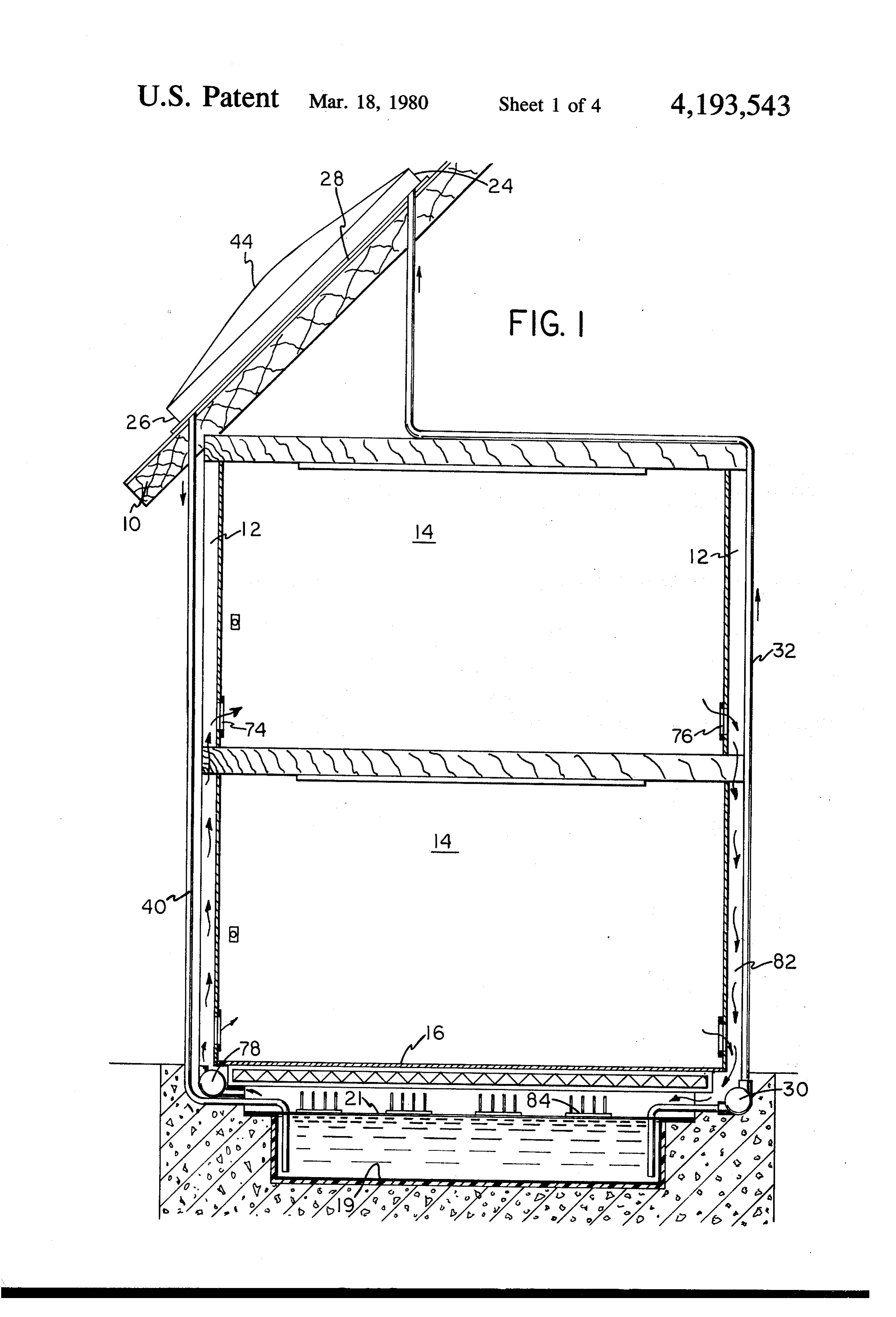
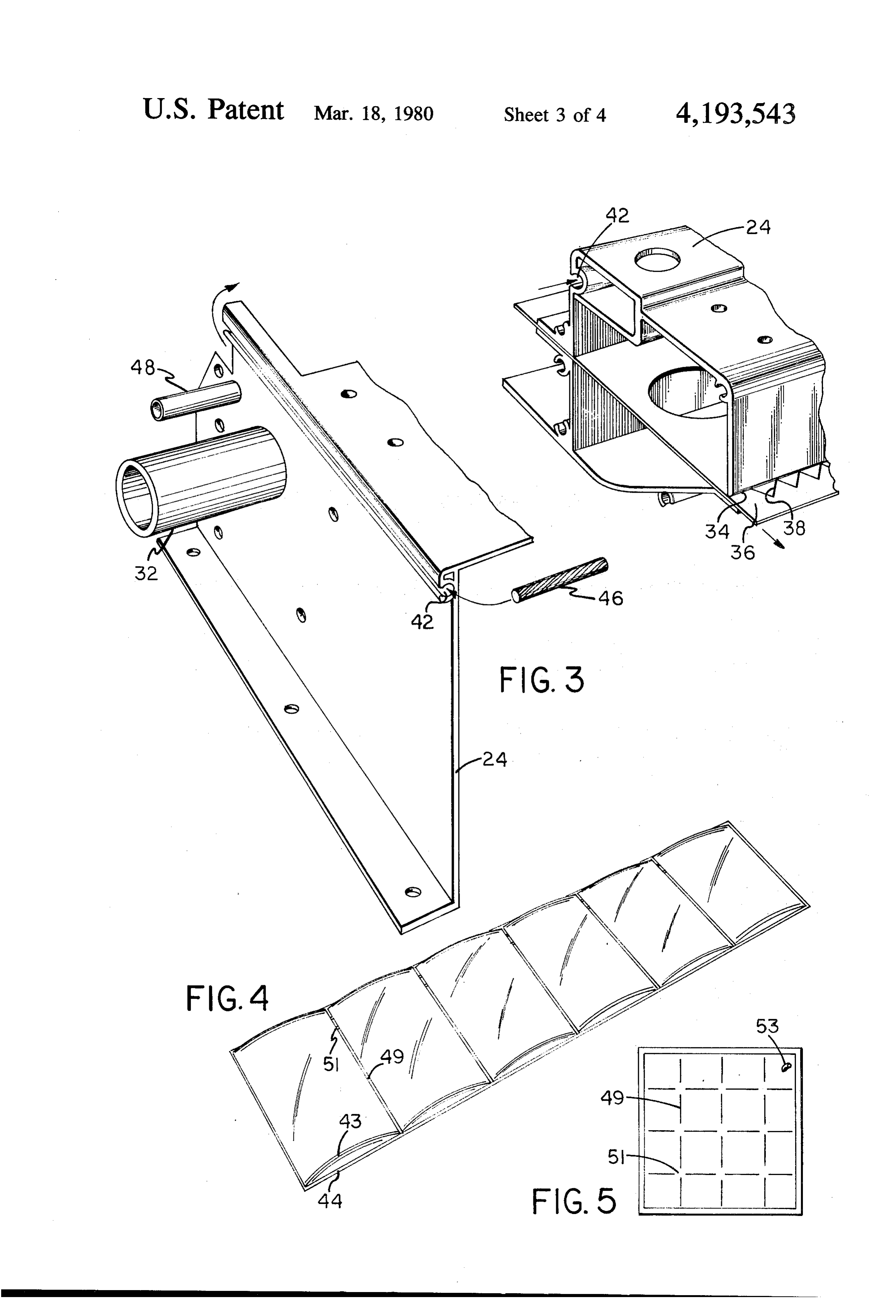
FIG. 1 is a vertical cross sectional view of one em the chamber is heated by solar energy this manner. bodiment of the invention. A transparent thin flexible plastic sheet 39 is secured FIG. 2 is an enlarged detail view of a pertion of the 45 peripherally to the supporting frame and is parallel to structure shown in FIG. 1. and spaced closely above plate 22. This will prevent FIG. 3 is a detail view of a portion of the structure of condensation under the outer cover 44 (this cover is the solar heat collecting unit. discussed in more detail below) and will minimize loss FIG. 4 is a detail view of an alternate arrangement for of collected heat.
a plastic cover. 50 The outside surfaces of member 24, 26 and 28 have an FIG. 5 illustrates another modification of a plastic aligned horizontally elongated peripheral groove 42. COWe. The sheet 39 is covered by a flexible transparent inflat FIG. 6 below is a vertical cross sectional view of the able cover 44 held in place by a rope 46 or other means upper member of the solar heat collecting unit. disposed removably in groove 42. An electrically oper 55 ated pump 50 pumps air in the enclosed space between
DETAILED DESCRIPTION OF PREFERRE cover 44 and sheet 39 via feed tube 48 to inflate the EMBODIMENTS cover which then protects the plate 22 from external Referring now to the drawings, a building is provided weather conditions. The cover can be replaced as re with a roof 10, vertical walls 12, interior rooms 14 and quired. The pump has a pressure control which is preset a bottom floor 16. Disposed below removable floor 16 is to maintain the pressure within the enclosed space at a a hollow water proof chamber 18 partially filled with small preselected positive pressure relative to atmo water to level 20. The chamber is lined with plastic as spheric, thus maintaining the condition of inflation de shown at 19. A plastic cover, thin and flexible, rests on sired. The control cuts the pump off as often as neces the top surface of the water as shown at 21. The protion sary to prevent over inflation.
of the chamber above cover 21 contains air. 65 In some geographic areas, two weather cover sheets A solar heat collecting unit is disposed on the roof. It may be used disposed one above the other, being sepa includes a flat inclined plate 22 typically of thin anod rated by air under small positive pressure as shown in ized aluminum foil, painted black and having a rough FIG. 4. These sheets may be attached to each other as
Page 7
shown at 43 and 45 in regular intervals by a heat sealing ber having a water outlet and an elongated hori process forming multiple adjacent domes connected to Zontal slot, said slot extending along the length of each other by partitions 49 having small interconnect the lower member adjacent said sheet; ing air passage 51 and inflated by the same source of air first means interconnecting said chamber and said under pressure that is controlled and maintained from water inlet to pump water from said chamber to outside. said inlet, said water flowing out of said horizontal The interiors of the rooms 14 contain supply airports opening over said sheet for collection in said lower 74 and return air ports 76. Fans 78 pull air from the member, the water being heated by solar action as chamber and feed same under pressure through supply it flows over said sheet; ducts 80 to ports 74. Return air flows back through 10 second means interconnecting said water outlet to ports 76 and return ducts 82 to the chamber. When the said chamber to drain said heated water into said air in the chamber is heated, it is apparent that the air chamber;
discharged into the rooms will heat same in the manner a slidable perforated plate extending through said of conventional forced air heating system. upper member and said opening, said plate being In order to heat the air it is necessary to transfer heat 15 slidable to any position between fully closed and from the heated water in the chamber to the air in the fully open to regulate the flow of water through chamber. This is accomplished in the present embodi said opening accordingly, and thus regulate the ment by using a heat exchanger in the form of metal temperature of the water heated by flow along said members 84 formed of anodized aluminum or other plate;
good heat conductor. These members have flat horizon 20 a flexible transparent plastic cover; tal bottom surfaces which rest on the plastic cover 21 third means detachably securing said cover to said and receive heat from the water. The air used in heating upper and lower members, said cover extending is forced to flow over the top horizontal portion and the over said sheet to protect same for external vertical exposed surfaces of members 84 which are weather conditions; and disposed above the water level. Heat is thus transferred 25 fourth means to introduce air under pressure between from the water to the members 84 and then from the said cover and said sheet to inflate said cover. member 84 to the air. Some electrically operated air 2. The system of claim 1 wherein each end of the blowers may be necessary in the air chamber to facili upper member is secured to a corresponding end of the tate the heat transfer from water to air.
Thermostats, motorized dampers and other known end members 30 lower member by a corresponding one of two parallel control elements can be used to regulate the heat trans ber whereby said upper member, lower mem ferred to the rooms as desired for the desired heating including grooves in theform and end members a frame, said third means outer peripheral surfaces of all action. For periods when sufficient solar heat is not of said members, said cover having portions fitting available, auxiliary heating means must be used such as removably in said grooves, said third means further electric heat radiating ceiling panels or baseboard or the 35 including a cord removably disposed in said grooves like to supplement the needed difference.
The arrangement of two spaced cover sheets shown and3. overlying said cover portions. The system of claim 2 further including a transpar in FIG. 4 can be modified to form a rectangular array of ent thin plastic sheet secured peripherally to all of said domes 47 inflatable via inlet valve 53 as shown in FIG.
5. This array can be used as insulation for windows or 40 members, said plastic sheet being disposed parallel to the like as well as being employed in the manner de and spaced closely above the collector sheet within the scribed with respect to FIG. 4. inflated cover, said plastic sheet preventing condensa What is claimed is: tion under said cover.
1. A solar heating system for a building having an 4. The system of claim 1 further including a second inclined roof, side walls and a removable sectional bot 45 cover in said chamber resting upon the top surface of tom floor, said system comprising: the water therein; and a plurality of heat exchangers a closed hollow water proof chamber disposed below which are good thermal conductors, said exchangers said bottom floor, said chamber being partially having flat horizontal portions resting upon said film filled with water and containing air; and spaced vertical portions which extend upward from a solar heat collector disposed in the roof, said collec 50 the horizontal portions whereby heat from the water is tor having upper and lower spaced horizontal hol transferred to the air surrounding said vertical portions low members and a flat collector sheet having a of said exchangers and said air is heated.
roughened black top surface inclinedly disposed 5. The system of claim 4 further including fourth therebetween, the upper member having a water means to circulate said air around said exchangers, fifth inlet and an elongated horizontal opening, the hori 55 means to distribute said heated air to the interior of said Zontal opening extending along the length of the building. k k upper member adjacent the sheet, said lower mem
Provenance
- Collection
- Cited prior art
- Original PDF
- patentimages.storage.googleapis.com →
- Filed
- 1978-02-23
- Pages
- 7
- Method
- pdftotext (the PDF's own text layer) + pdftoppm 300dpi page scans
- Source
- Google Patents bibliographic record
- Granted
- 1980-03-18
- Inventors
- Eric A. Viesturs; Gundar E. Viesturs
- Transcribed from
- patentimages.storage.googleapis.com →