patent · US4149523
Solar energy collector system with cylindro-parabolic mirror
17 April 1979
Page 1 — bibliographic record
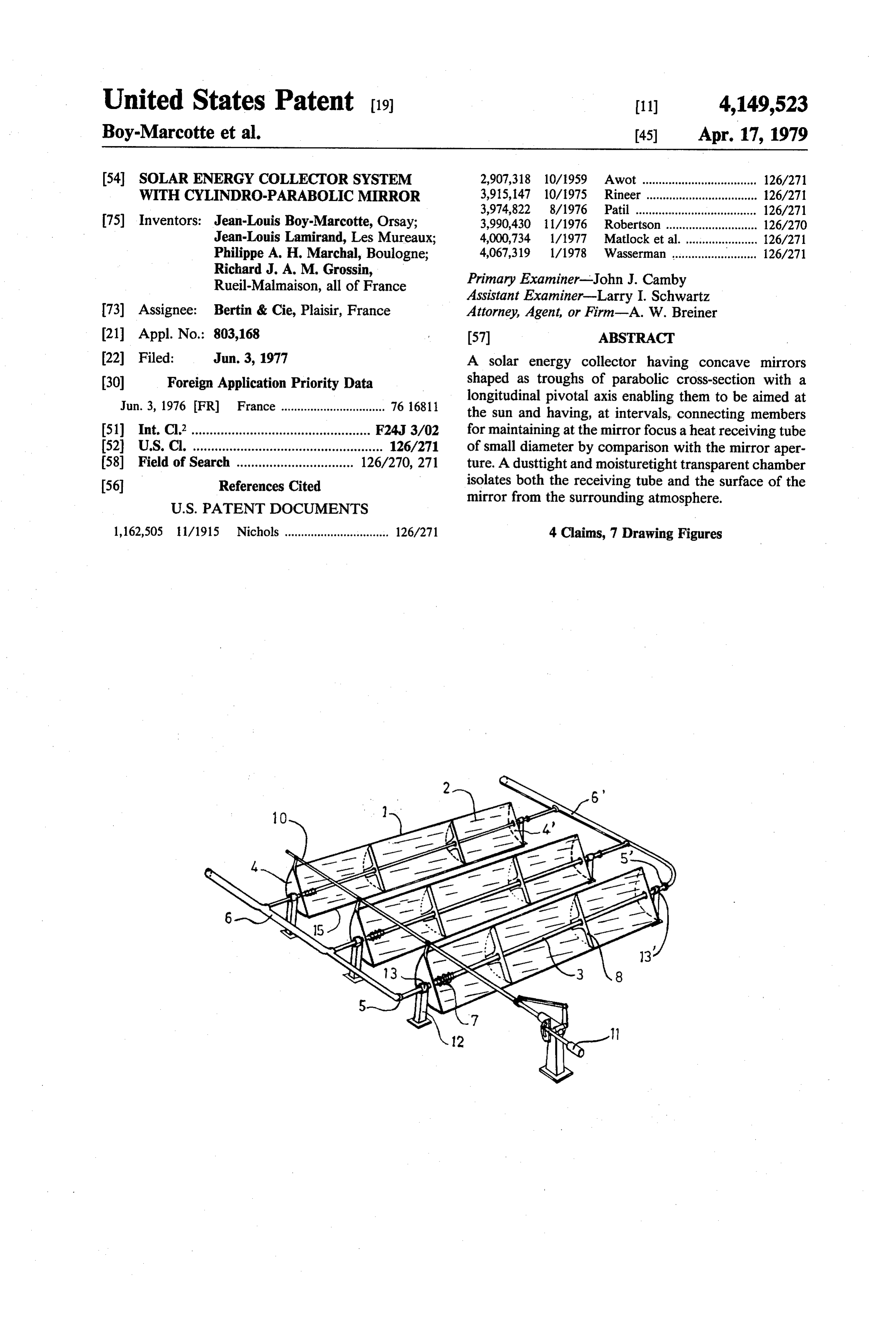
United States Patent (19) 11) 4,149,523 Boy-Marcotte et al. 45) Apr. 17, 1979 (54). SOLAR ENERGY COLLECTOR SYSTEM 2,907,318 10/1959 Awot ....... ... 126/271 WITH CYLNDRO-PARABOLIC MIRROR 3,915, 147 10/1975 Rineer. ... 126/271 3,974,822 8/1976 Patil ............. ... 126/271 75) Inventors: Jean-Louis Boy-Marcotte, Orsay; 3,990,430 1 1/1976 Robertson ........ ... 126/270 Jean-Louis Lamirand, Les Mureaux; 4,000,734 1/1977 Matlock et al....... ... 126/271 Philippe A. H. Marchal, Boulogne; 4,067,319 1/1978 Wasserman .......................... 126/271 Richard J. A. M. Grossin, Primary Examiner-John J. Camby
Rueil-Malmaison, all of France Assistant Examiner-Larry I. Schwartz 73) Assignee: Bertin & Cie, Plaisir, France Attorney, Agent, or Firm-A. W. Breiner 21 Appl. No.: 803,168 (57) ABSTRACT (22 Filed: Jun. 3, 1977 A solar energy collector having concave mirrors (30) Foreign Application Priority Data shaped as troughs of parabolic cross-section with a Jun. 3, 1976 FR) France ................................ 76 1681.1 longitudinal pivotal axis enabling them to be aimed at the sun and having, at intervals, connecting members 51) Int. Cl’................................................. F24J 3/02 for maintaining at the mirror focus a heat receiving tube 52 U.S. Cl. .................................................... 126/271 of small diameter by comparison with the mirror aper 58) Field of Search ................................ 126/270, 271 ture. A dusttight and moisturetight transparent chamber (56) References Cited isolates both the receiving tube and the surface of the
mirror from the surrounding atmosphere.
1,162,505 11/1915 Nichols ................................ 126/271 4 Claims, 7 Drawing Figures
Page 2
Drawing sheet — no readable text.
Page 3
Drawing sheet — no readable text.
Page 4
Such transparent chamber possesses the following
SOLAR ENERGY COLLECTOR SYSTEM WITH particularities:
CYLNDRO-PARABOLC MERROR (a) because it is airtight, dust deposits on the mirror are avoided;
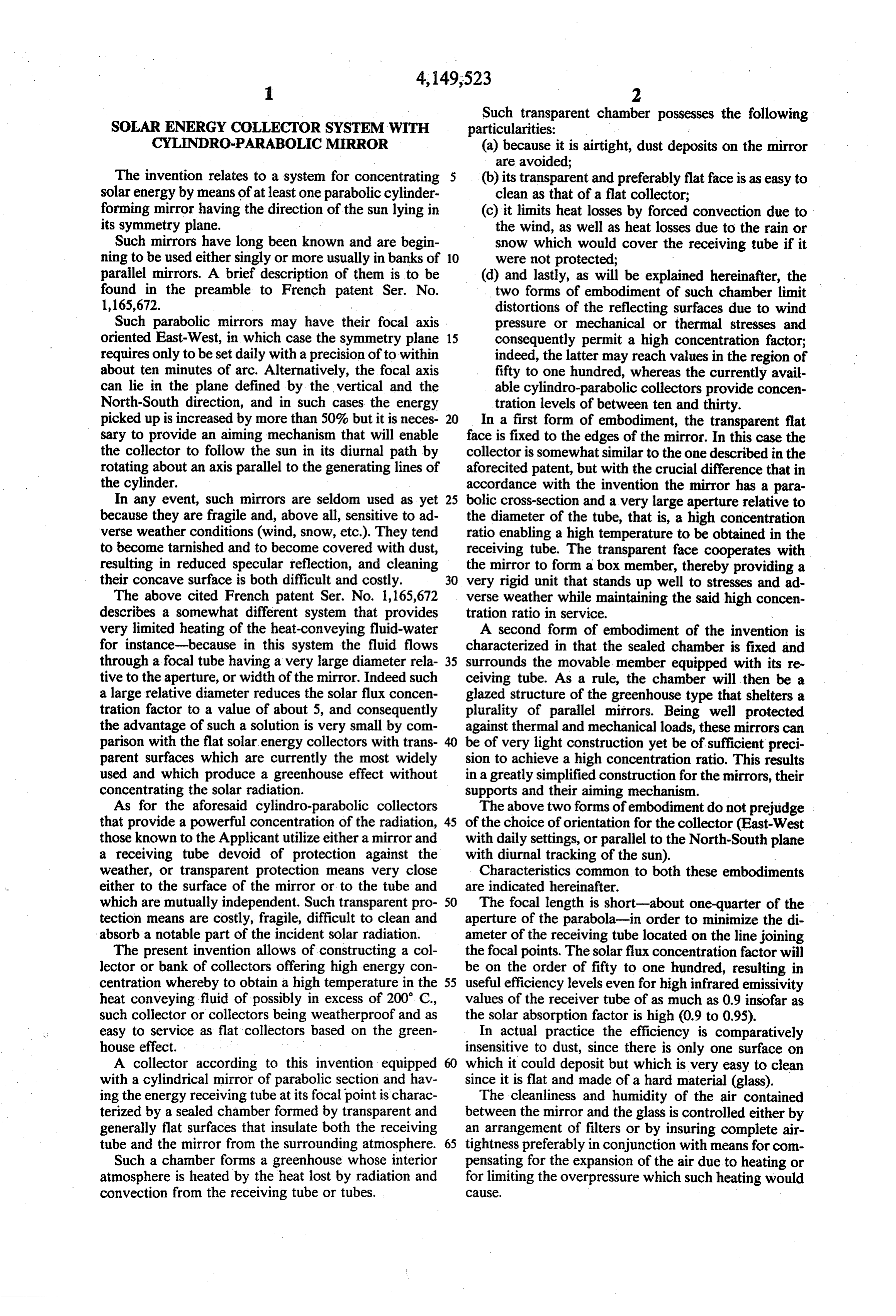
The invention relates to a system for concentrating 5 (b) its transparent and preferably flat face is as easy to solar energy by means of at least one parabolic cylinder clean as that of a flat collector; forming mirror having the direction of the sun lying in (c) it limits heat losses by forced convection due to its symmetry plane. the wind, as well as heat losses due to the rain or Such mirrors have long been known and are begin snow which would cover the receiving tube if it ning to be used either singly or more usually in banks of 10 were not protected;
parallel mirrors. A brief description of them is to be (d) and lastly, as will be explained hereinafter, the found in the preamble to French patent Ser. No. two forms of embodiment of such chamber limit 1,165,672. distortions of the reflecting surfaces due to wind Such parabolic mirrors may have their focal axis pressure or mechanical or thermal stresses and oriented East-West, in which case the symmetry plane 15 consequently permit a high concentration factor; requires only to be set daily with a precision of to within indeed, the latter may reach values in the region of about ten minutes of arc. Alternatively, the focal axis fifty to one hundred, whereas the currently avail can lie in the plane defined by the vertical and the able cylindro-parabolic collectors provide concen North-South direction, and in such cases the energy tration levels of between ten and thirty. picked up is increased by more than 50% but it is neces 20 In a first form of embodiment, the transparent flat sary to provide an aiming mechanism that will enable face is fixed to the edges of the mirror. In this case the the collector to follow the sun in its diurnal path by collector is somewhat similar to the one described in the rotating about an axis parallel to the generating lines of aforecited patent, but with the crucial difference that in the cylinder. accordance with the invention the mirror has a para In any event, such mirrors are seldom used as yet 25 bolic cross-section and a very large aperture relative to because they are fragile and, above all, sensitive to ad the diameter of the tube, that is, a high concentration verse weather conditions (wind, snow, etc.). They tend ratio enabling a high temperature to be obtained in the to become tarnished and to become covered with dust, receiving tube. The transparent face cooperates with resulting in reduced specular reflection, and cleaning the mirror to form a box member, thereby providing a their concave surface is both difficult and costly. 30 very rigid unit that stands up well to stresses and ad The above cited French patent Ser. No. 1,165,672 verse weather while maintaining the said high concen describes a somewhat different system that provides tration ratio in service.
very limited heating of the heat-conveying fluid-water A second form of embodiment of the invention is for instance-because in this system the fluid flows characterized in that the sealed chamber is fixed and through a focal tube having a very large diameter rela 35 surrounds the movable member equipped with its re tive to the aperture, or width of the mirror. Indeed such ceiving tube. As a rule, the chamber will then be a a large relative diameter reduces the solar flux concen glazed structure of the greenhouse type that shelters a tration factor to a value of about 5, and consequently plurality of parallel mirrors. Being well protected the advantage of such a solution is very small by com against thermal and mechanical loads, these mirrors can parison with the flat solar energy collectors with trans be of very light construction yet be of sufficient preci parent surfaces which are currently the most widely sion to achieve a high concentration ratio. This results used and which produce a greenhouse effect without in a greatly simplified construction for the mirrors, their concentrating the solar radiation. supports and their aiming mechanism. As for the aforesaid cylindro-parabolic collectors The above two forms of embodiment do not prejudge that provide a powerful concentration of the radiation, 45 of the choice of orientation for the collector (East-West those known to the Applicant utilize either a mirror and with daily settings, or parallel to the North-South plane a receiving tube devoid of protection against the with diurnal tracking of the sun).
weather, or transparent protection means very close Characteristics common to both these embodiments either to the surface of the mirror or to the tube and are indicated hereinafter.
which are mutually independent. Such transparent pro 50 The focal length is short-about one-quarter of the tection means are costly, fragile, difficult to clean and aperture of the parabola-in order to minimize the di absorb a notable part of the incident solar radiation. ameter of the receiving tube located on the line joining The present invention allows of constructing a col the focal points. The solar flux concentration factor will lector or bank of collectors offering high energy con be on the order of fifty to one hundred, resulting in centration whereby to obtain a high temperature in the 55 useful efficiency levels even for high infrared emissivity heat conveying fluid of possibly in excess of 200 C., values of the receiver tube of as much as 0.9 insofar as such collector or collectors being weatherproof and as the solar absorption factor is high (0.9 to 0.95). easy to service as flat collectors based on the green In actual practice the efficiency is comparatively house effect. insensitive to dust, since there is only one surface on A collector according to this invention equipped which it could deposit but which is very easy to clean with a cylindrical mirror of parabolic section and hav since it is flat and made of a hard material (glass). ing the energy receiving tube at its focal point is charac The cleanliness and humidity of the air contained terized by a sealed chamber formed by transparent and between the mirror and the glass is controlled either by generally flat surfaces that insulate both the receiving an arrangement of filters or by insuring complete air tube and the mirror from the surrounding atmosphere. 65 tightness preferably in conjunction with means for com Such a chamber forms a greenhouse whose interior pensating for the expansion of the air due to heating or atmosphere is heated by the heat lost by radiation and for limiting the overpressure which such heating would convection from the receiving tube or tubes. CauSC.
Page 5
The great length of the receiving tube (several me should lie within the closed unit formed by mirror 1 and ters) and its freedom of longitudinal expansion make it glazing 2. Flat end covers 4 and 4 of parabolic outline an excellent way of measuring the temperature of the close the ends of each unit, and elastic seals 15 render heat conveying fluid, for the end of the tube moves the space bounded by the mirror, the glazing and the through about 0.1mm per degree centigrade. Moreover end covers completely hermetic.
it can be used with advantage as a signal for controlling Each receiving tube 3 is rigidly fixed to covers 4, 4, the output of the heat-conveying fluid circulation through which it extends for communication via flexi pump. ble pipes or rotary seals 5 and 5 with manifolds 6 and 6 Should circulation of the fluid cease for any reason, for the heat conveying fluid flowing through it. The the mirror is aimed away from the direction of the sun 10 respective expansions of the different parts are absorbed in order to avoid boiling of the heat conveying fluid. by the elasticity of seals 15 and by deformation of the This aiming away can be controlled by the longitudinal end covers 4. If the latter are too thick and rigid, receiv expansion of the receiving tube beyond a threshold in ing tube 3 can be provided with expansion bellows 7 the region of 300° C. to 400 C. since the tube 3 may have its length increased by several Aiming accuracy implies an angle of less than 0.1 15 centimeters when it is heated. Intermediate struts 8 join degree between the symmetry plane of the collector the edges and/or the apex of the mirror to tube 3. and the direction of the sun. To achieve this accuracy, The overpressure produced by heating of the internal the control system must be demultiplied in a large ratio air can be avoided by balancing the internal and ambient (50 to 3600) by worm-screw, gear or lever systems. pressures, for instance through a filter (not shown) pref. In the case of the North-South collectors, automatic 20 erably in conjunction with dehydrating means in order means comprising a sun locating solar sensor, a control to avoid water condensation on the inside face of glaz logic and a power unit will enable the sun to be tracked ing 2.
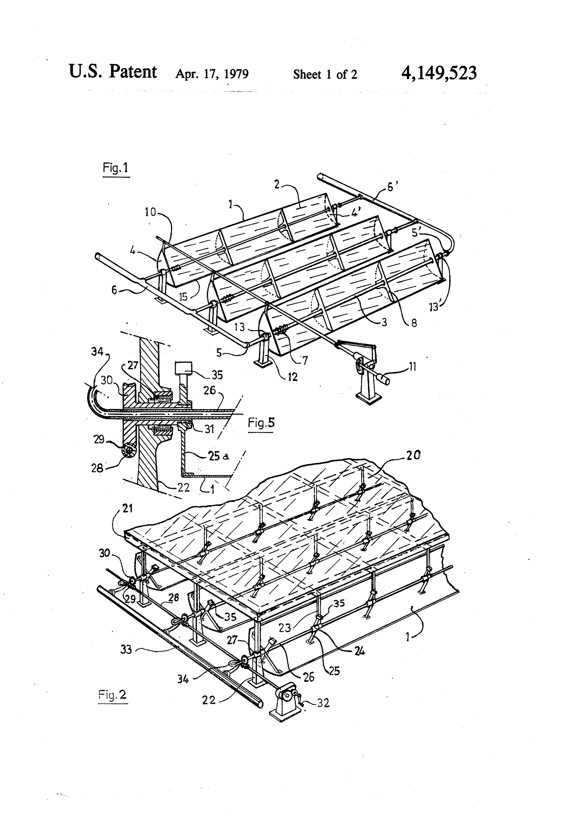
along its diurnal path. Each mirror in the bank of collectors shown in FIG. In the case of East-West collectors, a simple auto 1 is connected to its neighbors through rods 10 hingedly matic or possibly manual daily or weekly (depending on 25 connected to their upper edges and manually actuated the season) setting advice will suffice. by a lever 11 the position of which can be accurately A plurality of mirrors are coupled together in order located on a graduated sector whereby to permit collec to limit the number of aiming elements. The coupling tive adjustment of the optimum orientation of the sev means used for the purpose may be coupling bars, rods eral mirrors relative to the altitude of the sun. Each rod with screw-thread adjustments, cables, or the like. 30 10 includes fine adjustment means (not shown) for ad The control system enables the set of mirrors to be justing the parallelism of the planes of symmetry of the aimed at or away from the sun for start-ups or shut mirrors. Such parallelism can be maintained in opera downs. tion provided that a material with a low thermal expan Preferably, the axis of the receiving tube coincides sion coefficient is chosen for construction of said rods. with the pivotal axis of the mirror as the same moves to 35 Each mirror-glazing assembly is supported on the point at the sun. Said tube may even form the material ground by posts 12, and each post 12 is provided with a shaft for such pivotal motion, or may be fixed or cou bearing 13 for supporting the ends of tubes 3 proximate pled with the mirror. the rotary of flexible seals 5 or 5. The description which follows with reference to the The length of these mirror-glazing assemblies is lim accompanying non-limitative exemplary drawings of 40 ited by their degree of sag between bearings 3 and 13' the two main embodiments of the invention will give a owing to their weight.
clear understanding of how the same can be carried into DESCRIPTION OF SECOND FORM OF practice.
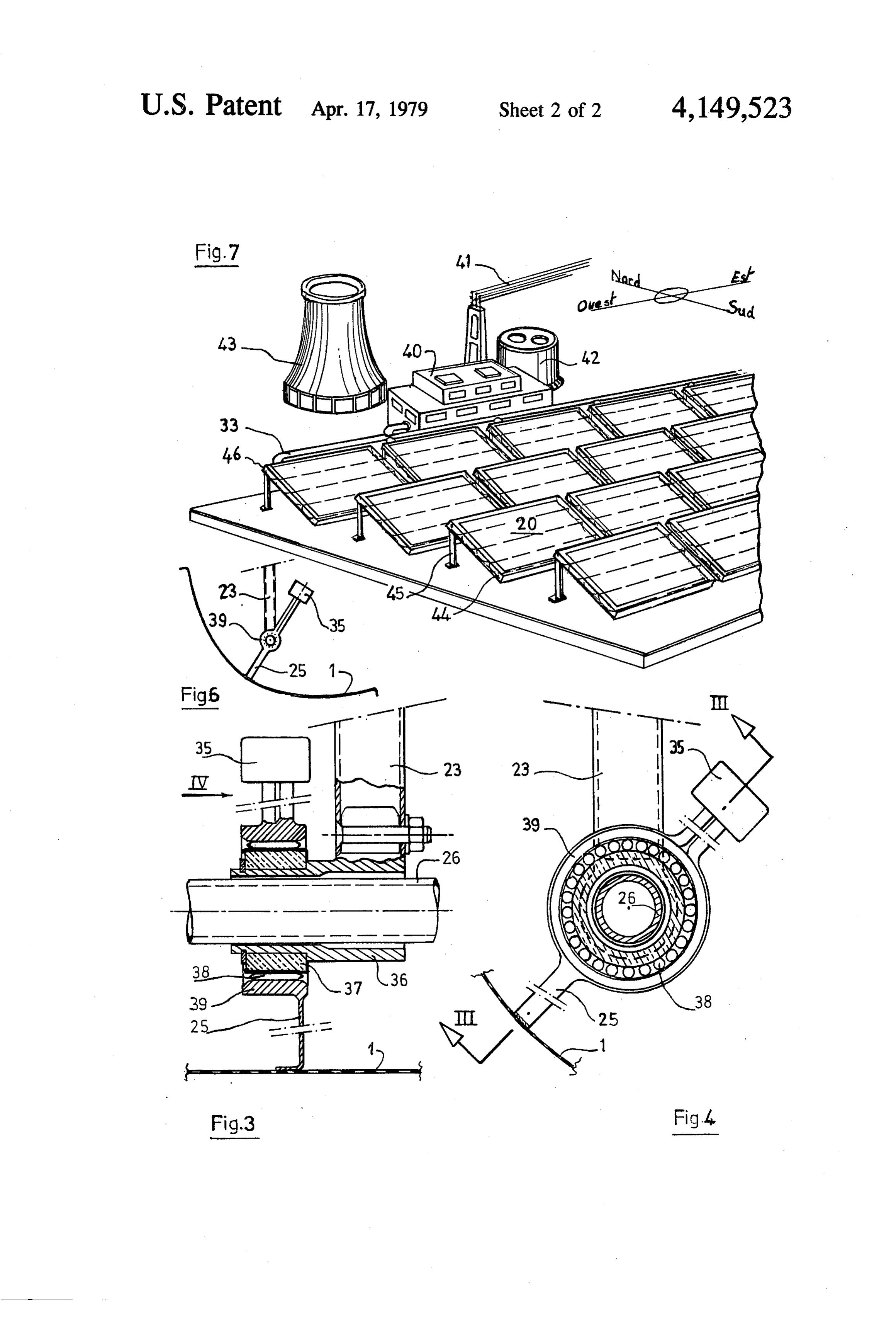
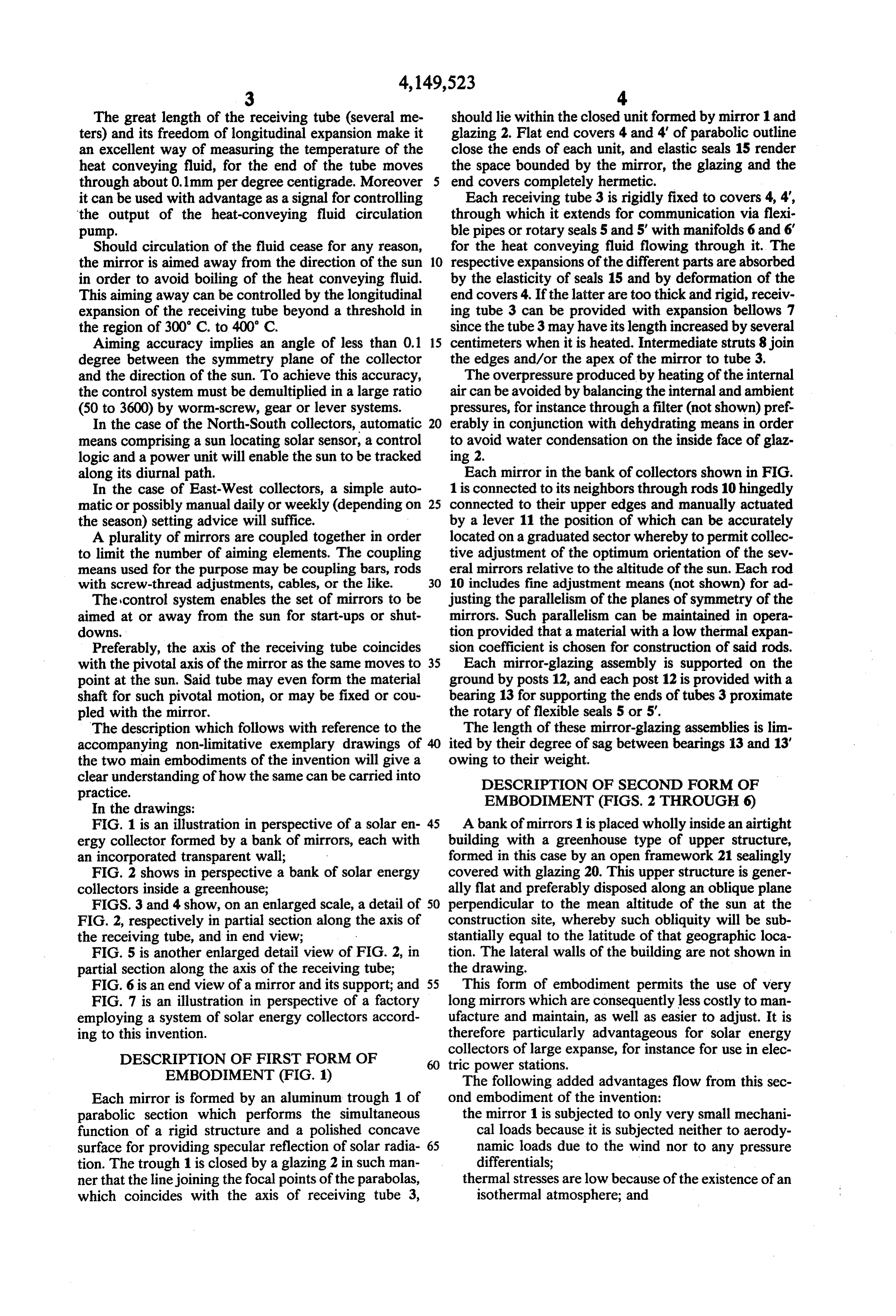
In the drawings: EMBODIMENT (FIGS. 2 THROUGH 6) FIG. 1 is an illustration in perspective of a solar en 45 A bank of mirrors 1 is placed wholly inside an airtight ergy collector formed by a bank of mirrors, each with building with a greenhouse type of upper structure, an incorporated transparent wall; formed in this case by an open framework 21 sealingly FIG. 2 shows in perspective a bank of solar energy covered with glazing 20. This upper structure is gener collectors inside a greenhouse; ally flat and preferably disposed along an oblique plane FIGS. 3 and 4 show, on an enlarged scale, a detail of 50 perpendicular to the mean altitude of the sun at the FIG. 2, respectively in partial section along the axis of construction site, whereby such obliquity will be sub the receiving tube, and in end view; stantially equal to the latitude of that geographic loca FIG. 5 is another enlarged detail view of FIG. 2, in tion. The lateral walls of the building are not shown in partial section along the axis of the receiving tube; the drawing.
FIG. 6 is an end view of a mirror and its support; and 55 This form of embodiment permits the use of very FIG. 7 is an illustration in perspective of a factory long mirrors which are consequently less costly to man employing a system of solar energy collectors accord ufacture and maintain, as well as easier to adjust. It is ing to this invention. therefore particularly advantageous for solar energy
DESCRIPTION OF FIRST FORM OF
collectors of large expanse, for instance for use in elec 60 tric power stations.
EMBODIMENT (FIG. 1) The following added advantages flow from this sec Each mirror is formed by an aluminum trough 1 of ond embodiment of the invention: parabolic section which performs the simultaneous the mirror 1 is subjected to only very small mechani function of a rigid structure and a polished concave cal loads because it is subjected neither to aerody surface for providing specular reflection of solar radia 65 namic loads due to the wind nor to any pressure tion. The trough 1 is closed by a glazing 2 in such man differentials;
ner that the line joining the focal points of the parabolas, thermal stresses are low because of the existence of an which coincides with the axis of receiving tube 3, isothermal atmosphere; and
Page 6
the protective glazing 20 is entirely independent of Tube 26 is free to expand longitudinally through the the mirror, thereby avoiding any stresses which sleeve 31 with minimum friction. This tube is not driven could steam from glazing/mirror connections. during aiming rotation of the mirror and is connected to Since the only distortions will be those stemming 5 manifold 33 through a lyre-shaped expansion union 34. essentially from the weight of the mirrors themselves, This arrangement avoids the use of a rotary or sliding this makes it advantageous to adopt relatively small joint with the manifold, thereby making it possible to provide durable sealing for the heat-conveying fluid apertures of about 0.5 to 2 meters and to limit as far as possible the thickness required for the rigidity of the circuit formed by the receiving tubes 26 and the mani reflecting surface (about one millimeter in the case of folds 33.
aluminum, for example), which surface may possibly be O Considering next the general construction of the strengthened by means of ribs (not shown). greenhouse type of protection for the solar energy col The low weight of the individual mirrors 1 enables lectors, the framework 21 shown in FIG. 2 may be each of them to be supported by framework 21, which formed by a flat box structure 44 made of metal lattice is itself supported, at a height above the ground at least work shown in FIG. 7. This box structure, the thickness equal to the aperture of the mirrors, by posts 22. Depen 15 of which is substantially equal to the mirror aperture, dent from the framework are intermediate supports 23 can be prefabricated.
terminating in bearings 24, and it is these intermediate Each box structure formed thus receives mirror sys supports 23 which permit the use of very long mirrors, tems which, for example, could be those described with as indicated precedingly. Hingedly connected to bear 20 the reference to FIGS. 2 through 5, and it is supported on ings 24 are arms 25 fixed to mirror 1. ground in a sloping position by means of posts 45 and
Additional means are provided which are likewise associated its upper structure is covered with glazing 20 and intended to reduce stress and distortion in the mirrors so sealing means.
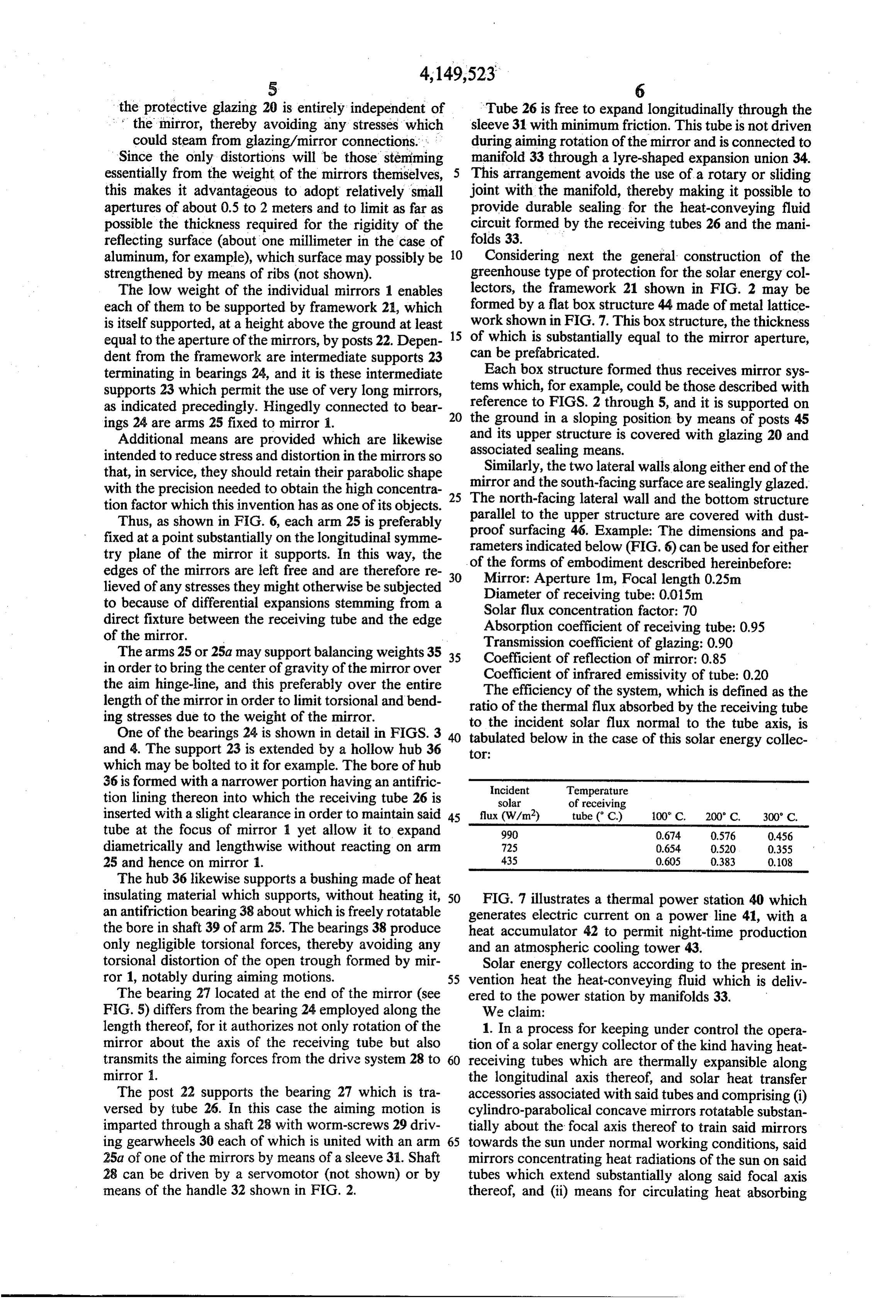
that, in service, they should retain their parabolic shape mirrorSimilarly, the two lateral walls along either end of the with the precision needed to obtain the high concentra and the south-facing surface are sealingly glazed. tion factor which this invention has as one of its objects. 25 The north-facing lateral wall and the bottom structure Thus, as shown in FIG. 6, each arm 25 is preferably parallel to the upper structure are covered with dust fixed at a point substantially on the longitudinal symme proof surfacing 46. Example: The dimensions and pa try plane of the mirror it supports. In this way, the of rameters indicated below (FIG. 6) can be used for either the forms of embodiment described hereinbefore:
edges of the mirrors are left free and are therefore re 30 Mirror: Aperture 1m, Focal length 0.25m lieved of any stresses they might otherwise be subjected Diameter of receiving tube: 0.015m to because of differential expansions stemming from a Solar flux concentration factor: 70 direct fixture between the receiving tube and the edge Absorption coefficient of receiving tube: 0.95 of the mirror.
The arms 25 or 25a may support balancing weights 35 35 Coefficient ofcoefficient
reflection of mirror: 0.85 in order to bring the center of gravity of the mirror over Coefficient of infrared emissivity of tube: 0.20 the aim hinge-line, and this preferably over the entire The efficiency of the system, which is defined as the length of the mirror in order to limit torsional and bend ratio of the thermal flux absorbed by the receiving tube ing stresses due to the weight of the mirror.
One of the bearings 24 is shown in detail in FIGS. 3 40 to the incident solar flux normal to the tube axis, is tabulated below in the case of this solar energy collec and 4. The support 23 is extended by a hollow hub 36 to:
which may be bolted to it for example. The bore of hub 36 is formed with a narrower portion having an antifric Incident Temperature tion lining thereon into which the receiving tube 26 is solar of receiving inserted with a slight clearance in order to maintain said 45 flux (W/m2) tube ( C.) 100 C. 200 C. 300 C. tube at the focus of mirror 1 yet allow it to expand 990 0.64 0.576 0.456 diametrically and lengthwise without reacting on arm 725 0.654 0.520 0.355 25 and hence on mirror . 435 0.605 0.383 0.108 The hub 36 likewise supports a bushing made of heat insulating material which supports, without heating it, 50 FIG. 7 illustrates a thermal power station 40 which an antifriction bearing 38 about which is freely rotatable generates electric current on a power line 41, with a the bore in shaft 39 of arm 25. The bearings 38 produce heat accumulator 42 to permit night-time production only negligible torsional forces, thereby avoiding any and an atmospheric cooling tower 43. torsional distortion of the open trough formed by mir Solar energy collectors according to the present in ror 1, notably during aiming motions. 55 vention heat the heat-conveying fluid which is deliv The bearing 27 located at the end of the mirror (see ered to the power station by manifolds 33. FIG. 5) differs from the bearing 24 employed along the We claim:
length thereof, for it authorizes not only rotation of the 1. In a process for keeping under control the opera mirror about the axis of the receiving tube but also tion of a solar energy collector of the kind having heat transmits the aiming forces from the drive system 28 to 60 receiving tubes which are thermally expansible along mirror 1. the longitudinal axis thereof, and solar heat transfer The post 22 supports the bearing 27 which is tra accessories associated with said tubes and comprising (i) versed by tube 26. In this case the aiming motion is cylindro-parabolical concave mirrors rotatable substan imparted through a shaft 28 with worm-screws 29 driv tially about the focal axis thereof to train said mirrors ing gearwheels 30 each of which is united with an arm 65 towards the sun under normal working conditions, said 25a of one of the mirrors by means of a sleeve 31. Shaft mirrors concentrating heat radiations of the sun on said 28 can be driven by a servomotor (not shown) or by tubes which extend substantially along said focal axis means of the handle 32 shown in FIG. 2. thereof, and (ii) means for circulating heat absorbing
Page 7
fluid through said tubes to carry away therefrom the 2. Process as claimed in claim 1, wherein the overheat checking step comprises de-training said mirrors away absorbed heat, the improvement comprises the steps of from the sun.
detecting excessive longitudinal expansion of said tubes 3. Process as claimed in claim 2, wherein said mirrors. due to overheating thereof, and applying the thus de are de-trained away from the sun when the detected tected excessive longitudinal expansion to check said expansion corresponds to a temperature of about 300 to overheating by action upon said solar heat transfer 400' C.
4. Process as claimed in claim 1, wherein the overheat accessories either by reducing the amount of heat input checking step comprises accelerating the circulation of provided from said mirrors or by increasing heat output 10 said fluid.
carried by said circulated fluid.

Provenance
- Collection
- Cited prior art
- Original PDF
- patentimages.storage.googleapis.com →
- Filed
- 1977-06-03
- Pages
- 7
- Method
- pdftotext (the PDF's own text layer) + pdftoppm 300dpi page scans
- Source
- Google Patents bibliographic record
- Granted
- 1979-04-17
- Inventors
- Jean-Louis Boy-Marcotte; Jean-Louis Lamirand; Philippe A. H. Marchal; Richard J. A. M. Grossin; Bertin et Cie SA
- Transcribed from
- patentimages.storage.googleapis.com →