patent · US4433199
Solar insolation and concentration by coupled fiber optics
21 February 1984
Page 1 — bibliographic record
United States Patent (19) 11) 4,433,199 Middy (45) Feb. 21, 1984 (54). SOLAR INSOLATION AND 4,350,837 9/1982 Clark ................................... 36/246 CONCENTRATION BY COUPLED FIBER 4,367,366 1/1983 Bloss et al. .......................... 136/246 OPTICS Primary Examiner-Aaron Weisstuch 76) Inventor: Gerald W. Middy,938 20th St., Santa Attorney, Agent, or Firm-William H. Maxwell Monica, Calif. 90403 57 ABSTRACT 21 Appl. No.: 389,440 A plurality of bundles of fiber optic light pipes are each 22 Filed: Jun. 17, 1982 arranged for the reception of a selected color band of 51 Int. C. ............................................. H01, 31/04 monochromatic light emanating through a prism with (52) which they act in combination as a secondary concen 58 trator. Incoming multiple wavelength sunlight from a primary concentrator is directed through said prism, (56) References Cited and photovoltaic cells are positioned at a spectrum
4,021,267 5/1977 Dettling .............................. 136/246 selected color bands of the spectrum. 4,151,005 4/1979 Strebkov et al. ... 136/256 4,210,121 7/1980 Stark .................................. 126/424 8 Claims, 9 Drawing Figures
Page 2
Drawing sheet — no readable text.
Page 3
Drawing sheet — no readable text.
Page 4
Drawing sheet — no readable text.
Page 5
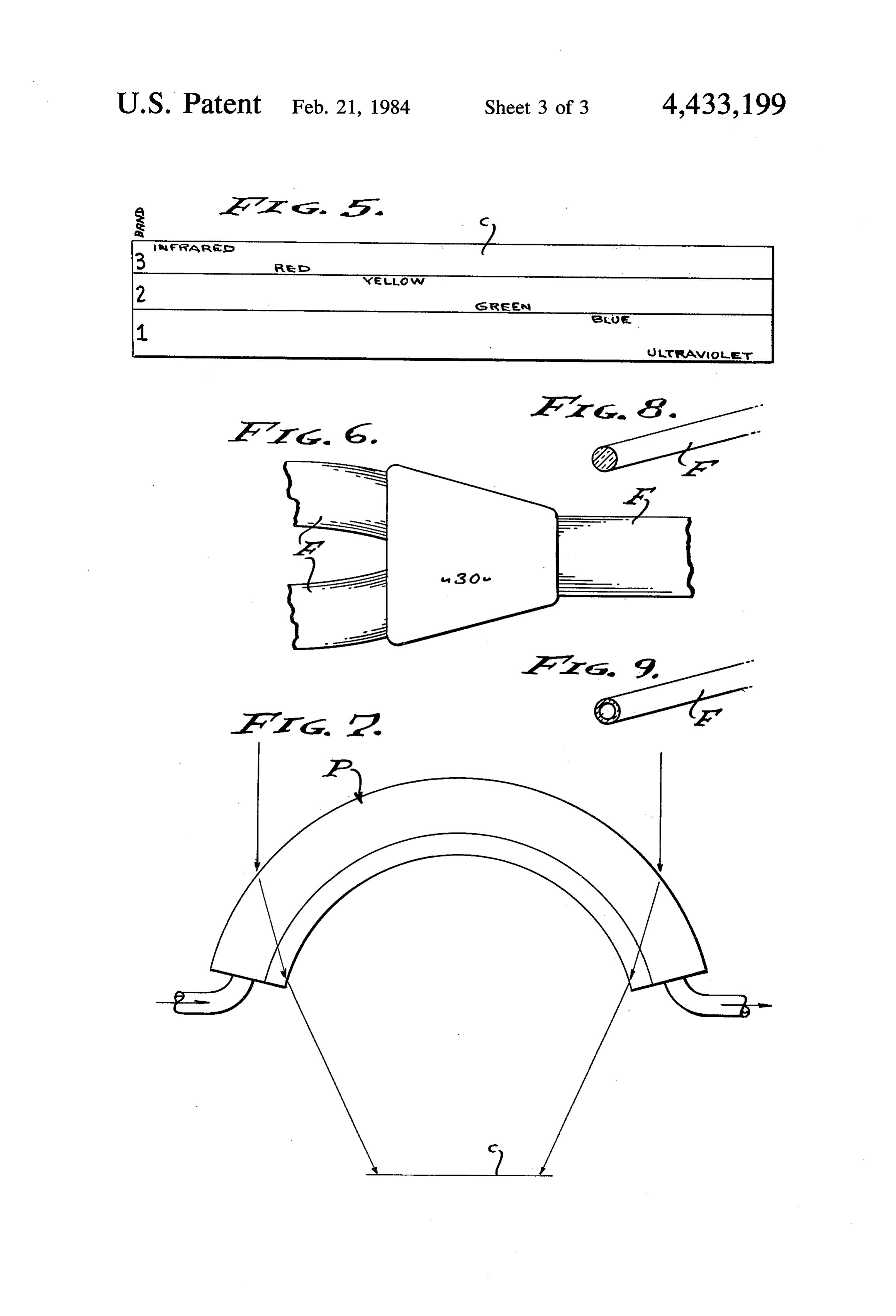
ing plane, or planes. Accordingly, the entire source area
SOLAR NSOLATION AND CONCENTRATION BY or plane is arranged selectively according to light COUPLED FIBER OPTICS wavelength, and the bundles of light pipes are selec tively directed onto a plurality of photovoltaic cells that
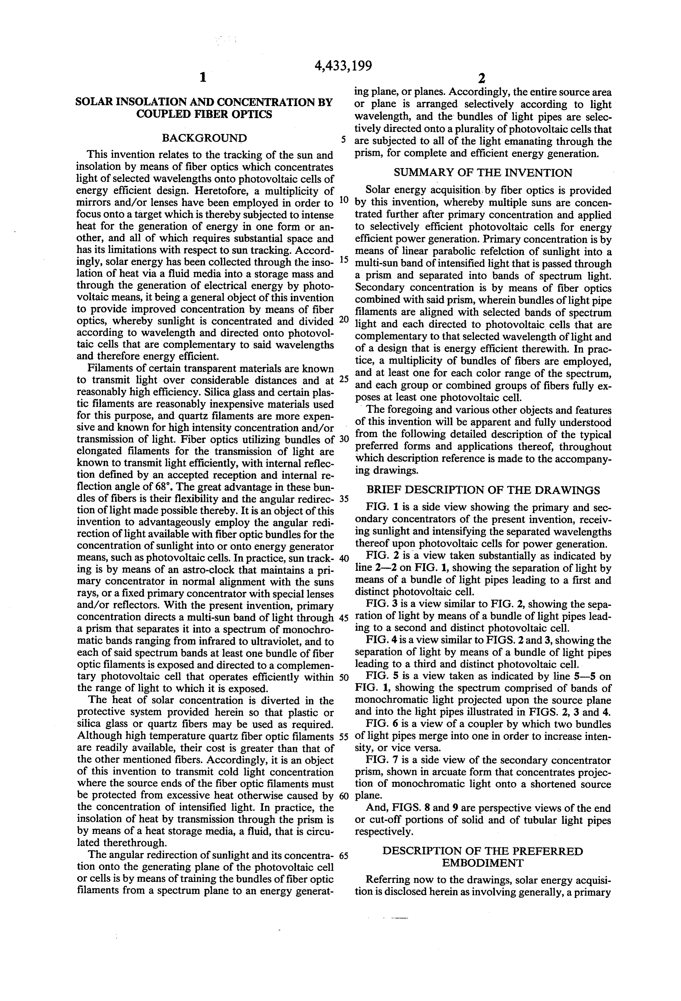
BACKGROUND are subjected to all of the light emanating through the This invention relates to the tracking of the sun and prism, for complete and efficient energy generation. insolation by means of fiber optics which concentrates SUMMARY OF THE INVENTION light of selected wavelengths onto photovoltaic cells of energy efficient design. Heretofore, a multiplicity of O Solar energy acquisition, by fiber optics is provided mirrors and/or lenses have been employed in order to by this invention, whereby multiple suns are concen focus onto a target which is thereby subjected to intense trated further after primary concentration and applied heat for the generation of energy in one form or an to selectively efficient photovoltaic cells for energy other, and all of which requires substantial space and efficient power generation. Primary concentration is by has its limitations with respect to sun tracking. Accord 15 means of linear parabolic refelction of sunlight into a ingly, solar energy has been collected through the inso multi-sun band of intensified light that is passed through lation of heat via a fluid media into a storage mass and a prism and separated into bands of spectrum light. through the generation of electrical energy by photo Secondary concentration is by means of fiber optics voltaic means, it being a general object of this invention combined with said prism, wherein bundles of light pipe to provide improved concentration by means of fiber filaments are aligned with selected bands of spectrum optics, whereby sunlight is concentrated and divided 20 light and each directed to photovoltaic cells that are according to wavelength and directed onto photovol complementary to that selected wavelength of light and taic cells that are complementary to said wavelengths of a design that is energy efficient therewith. In prac and therefore energy efficient. tice, a multiplicity of bundles of fibers are employed, Filaments of certain transparent materials are known and at least one for each color range of the spectrum, to transmit light over considerable distances and at 25 reasonably high efficiency. Silica glass and certain plas and poses each group or combined groups of fibers fully ex at least one photovoltaic cell.
tic filaments are reasonably inexpensive materials used for this purpose, and quartz filaments are more expen of this foregoing
The invention and various other objects and features will be apparent and fully understood sive and known for high intensity concentration and/or from the following detailed description of the typical transmission of light. Fiber optics utilizing bundles of 30 preferred forms and applications elongated filaments for the transmission of light are which description reference is madethereof, throughout to the accompany known to transmit light efficiently, with internal reflec ing drawings.
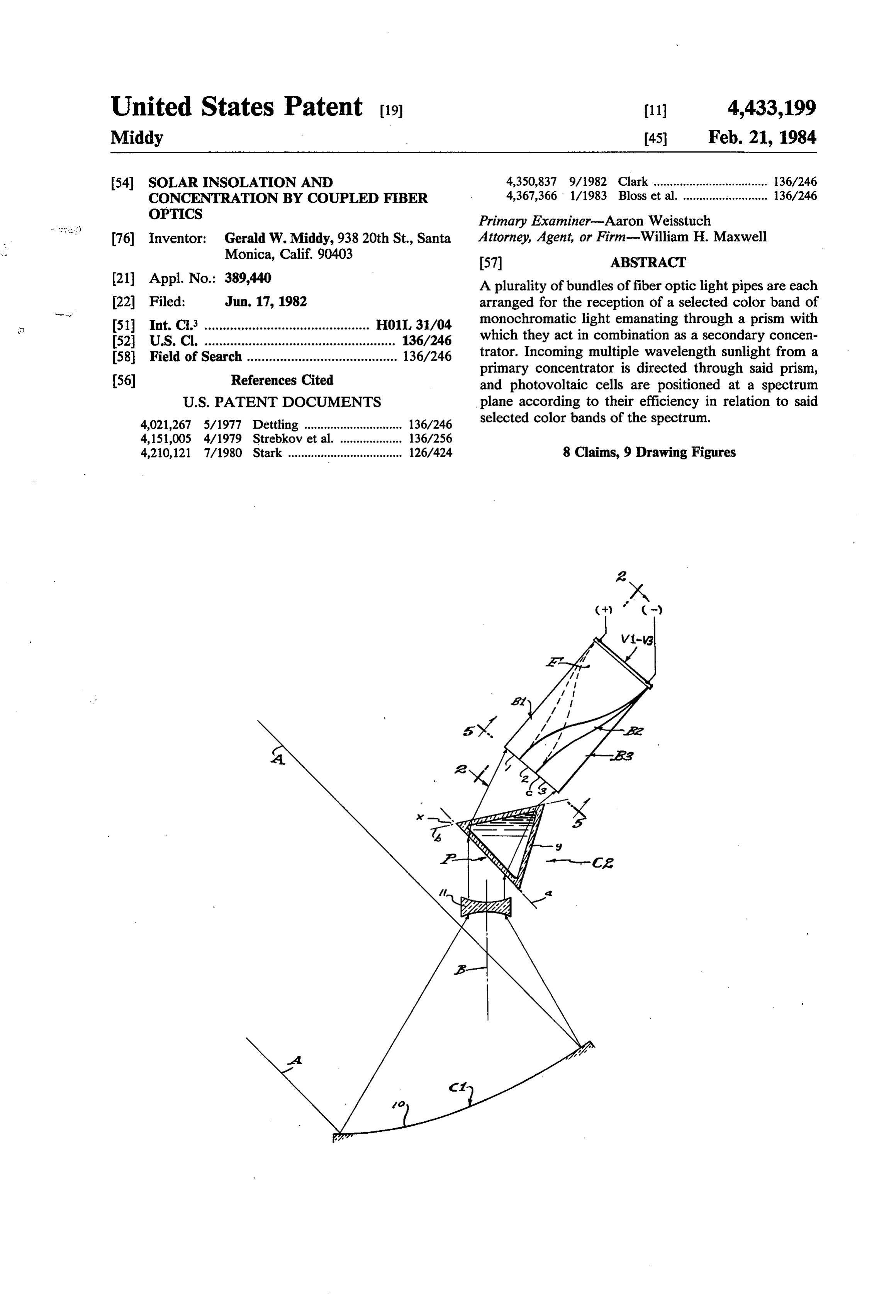
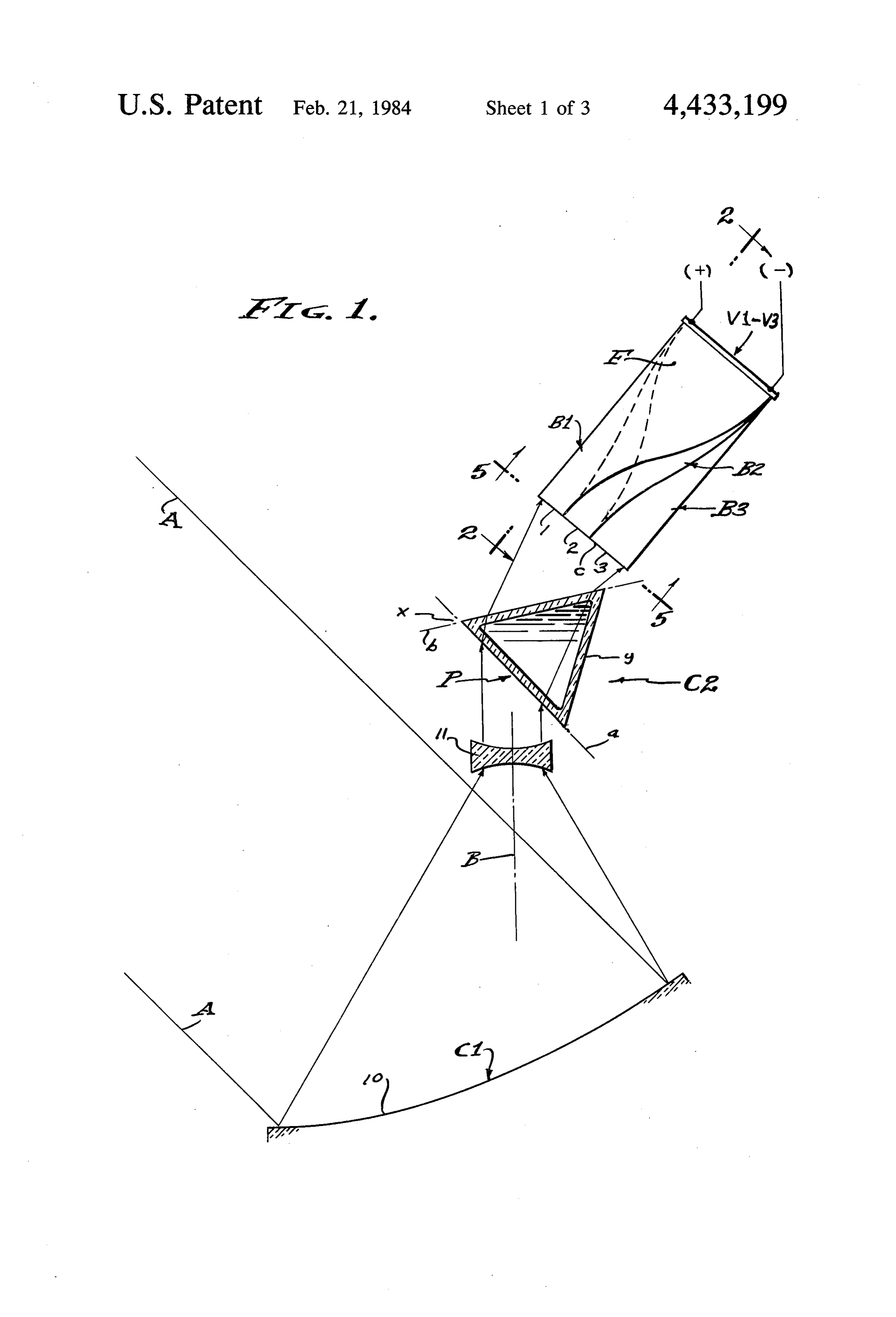
tion defined by an accepted reception and internal re flection angle of 68. The great advantage in these bun BRIEF DESCRIPTION OF THE DRAWINGS dles of fibers is their flexibility and the angular redirec 35 tion of light made possible thereby. It is an object of this FIG. 1 is a side view showing the primary and sec invention to advantageously employ the angular redi ondary concentrators of the present invention, receiv rection of light available with fiber optic bundles for the ing sunlight and intensifying the separated wavelengths concentration of sunlight into or onto energy generator thereof upon photovoltaic cells for power generation. means, such as photovoltaic cells. In practice, sun track FIG. 2 is a view taken substantially as indicated by ing is by means of an astro-clock that maintains a pri line 2-2 on FIG. 1, showing the separation of light by mary concentrator in normal alignment with the suns means of a bundle of light pipes leading to a first and rays, or a fixed primary concentrator with special lenses distinct photovoltaic cell.
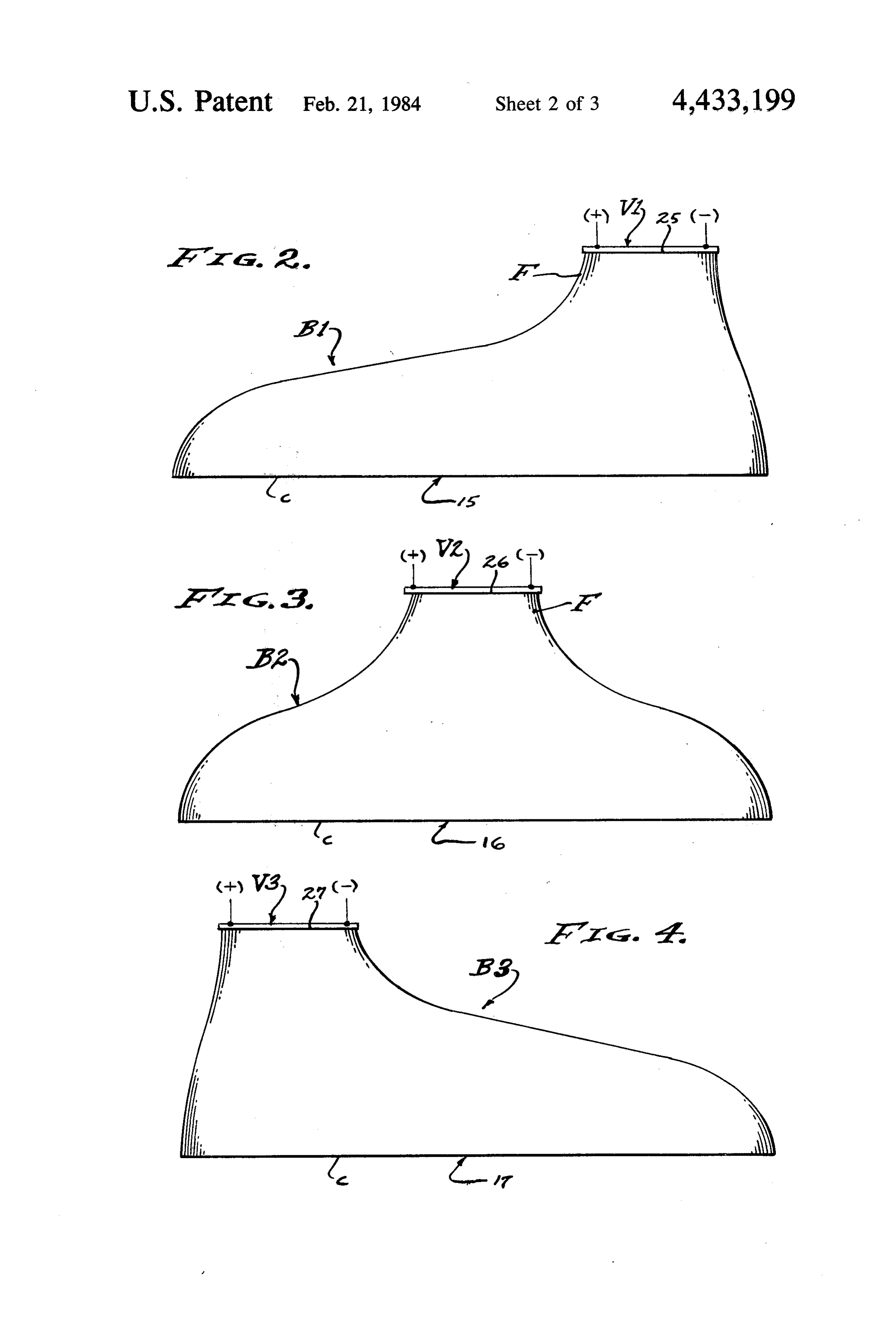
and/or reflectors. With the present invention, primary FIG. 3 is a view similar to FIG. 2, showing the sepa concentration directs a multi-sun band of light through 45 ration of light by means of a bundle of light pipes lead a prism that separates it into a spectrum of monochro ing to a second and distinct photovoltaic cell. matic bands ranging from infrared to ultraviolet, and to FIG. 4 is a view similar to FIGS. 2 and 3, showing the each of said spectrum bands at least one bundle of fiber separation of light by means of a bundle of light pipes optic filaments is exposed and directed to a complemen leading to a third and distinct photovoltaic cell. tary photovoltaic cell that operates efficiently within 50 FIG. 5 is a view taken as indicated by line 5-5 on the range of light to which it is exposed. FIG. 1, showing the spectrum comprised of bands of The heat of solar concentration is diverted in the monochromatic light projected upon the source plane protective system provided herein so that plastic or and into the light pipes illustrated in FIGS. 2, 3 and 4. silica glass or quartz fibers may be used as required. FIG. 6 is a view of a coupler by which two bundles Although high temperature quartz fiber optic filaments 55 of light pipes merge into one in order to increase inten are readily available, their cost is greater than that of sity, or vice versa.
the other mentioned fibers. Accordingly, it is an object FIG. 7 is a side view of the secondary concentrator of this invention to transmit cold light concentration prism, shown in arcuate form that concentrates projec where the source ends of the fiber optic filaments must tion of monochromatic light onto a shortened source be protected from excessive heat otherwise caused by plane.
the concentration of intensified light. In practice, the And, FIGS. 8 and 9 are perspective views of the end insolation of heat by transmission through the prism is or cut-off portions of solid and of tubular light pipes by means of a heat storage media, a fluid, that is circu respectively.
lated therethrough. DESCRIPTION OF THE PREFERRED The angular redirection of sunlight and its concentra 65 EMBODIMENT tion onto the generating plane of the photovoltaic cell or cells is by means of training the bundles of fiber optic Referring now to the drawings, solar energy acquisi filaments from a spectrum plane to an energy generat tion is disclosed herein as involving generally, a primary
Page 6
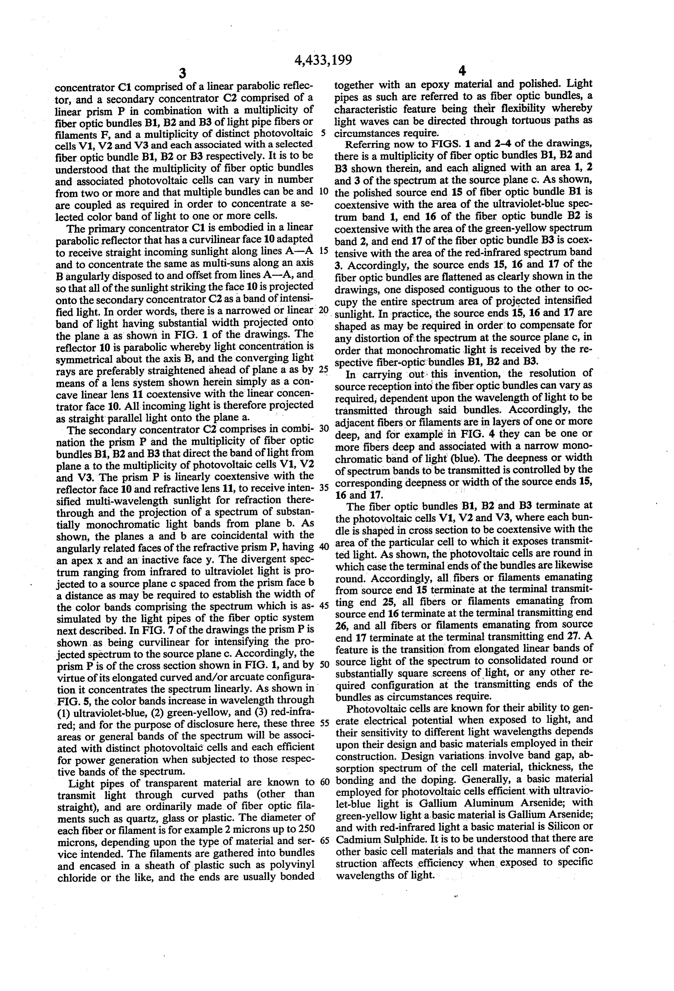
concentrator C1 comprised of a linear parabolic reflec together with an epoxy material and polished. Light tor, and a secondary concentrator C2 comprised of a pipes as such are referred to as fiber optic bundles, a linear prism P in combination with a multiplicity of characteristic feature being their flexibility whereby fiber optic bundles B1, B2 and B3 of light pipe fibers or 5 light waves can be directed through tortuous paths as filaments F, and a multiplicity of distinct photovoltaic circumstances require.
cells V1,V2 and V3 and each associated with a selected Referring now to FIGS. 1 and 2-4 of the drawings, fiber optic bundle B1, B2 or B3 respectively. It is to be there is a multiplicity of fiber optic bundles B1, B2 and understood that the multiplicity of fiber optic bundles B3 shown therein, and each aligned with an area 1, 2 and associated photovoltaic cells can vary in number and 3 of the spectrum at the source plane c. As shown, from two or more and that multiple bundles can be and O the polished source end 15 of fiber optic bundle B1 is are coupled as required in order to concentrate a se coextensive with the area of the ultraviolet-blue spec lected color band of light to one or more cells. trum band 1, end 16 of the fiber optic bundle B2 is The primary concentrator C1 is embodied in a linear coextensive with the area of the green-yellow spectrum parabolic reflector that has a curvilinear face 10 adapted 15 band 2, and end 17 of the fiber optic bundle B3 is coex to receive straight incoming sunlight along lines A-A tensive with the area of the red-infrared spectrum band and to concentrate the same as multi-suns along an axis 3. Accordingly, the source ends 15, 16 and 17 of the Bangularly disposed to and offset from lines A-A, and fiber optic bundles are flattened as clearly shown in the so that all of the sunlight striking the face 10 is projected drawings, one disposed contiguous to the other to oc onto the secondary concentrator C2 as aband of intensi cupy the entire spectrum area of projected intensified fied light. In order words, there is a narrowed or linear 20 sunlight. In practice, the source ends 15, 16 and 17 are band of light having substantial width projected onto shaped as may be required in order to compensate for the plane a as shown in FIG. 1 of the drawings. The any distortion of the spectrum at the source plane c, in reflector 10 is parabolic whereby light concentration is order that monochromatic light is received by the re symmetrical about the axis B, and the converging light spective fiber-optic bundles B1, B2 and B3. rays are preferably straightened ahead of plane a as by 25 In carrying means of a lens system shown herein simply as a con source receptionout: into this invention, the resolution of the fiber optic bundles can vary as cave linear lens 11 coextensive with the linear concen required, dependent upon the wavelength of light to be trator face 10. All incoming light is therefore projected transmitted through said bundles. Accordingly, the as straight parallel light onto the plane a. ,
The secondary concentrator C2 comprises in combi 30 adjacent fibers or filaments are in layers of one or more nation the prism P and the multiplicity of fiber optic more fibersfordeep deep, and example in FIG. 4 they can be one or bundles B1, B2 and B3 that direct the band of light from chromatic band ofand associated with a narrow mono plane a to the multiplicity of photovoltaic cells V1,V2 of spectrum bands tolight (blue). The deepness or width and V3. The prism P is linearly coextensive with the corresponding deepness or width ofisthecontrolled
source ends 15, reflector face 10 and refractive lens 11, to receive inten 35 16 and 17.
sified multi-wavelength sunlight for refraction there through and the projection of a spectrum of substan theThe fiber optic bundles B1, B2 and B3 terminate at photovoltaic cells V1,V2 and V3, where each bun tially monochromatic light bands from plane b. As dle is shaped in cross shown, the planes a and b are coincidental with the area of the particular section cell to to be coextensive with the which it exposes transmit angularly related faces of the refractive prism P, having an apex x and an inactive facey. The divergent spec ted light. As shown, the photovoltaic cells are round in trum ranging from infrared to ultraviolet light is pro which round.
case the terminal ends of the bundles are likewise
Accordingly, all fibers or filaments emanating jected to a source plane c spaced from the prism face b from source a distance as may be required to establish the width of ting end 25,end 15 terminate at the terminal transmit all fibers or filaments emanating from the color bands comprising the spectrum which is as 45 source end 16 terminate at the terminal transmitting end simulated by the light pipes of the fiber optic system 26, and all fibers or filaments next described. In FIG. 7 of the drawings the prism P is end 17 terminate at the terminalemanating from source transmitting end 27. A shown as being curvilinear for intensifying the pro feature is the transition from elongated linear bands of jected spectrum to the source plane c. Accordingly, the prism P is of the cross section shown in FIG. 1, and by 50 source light of the spectrum to consolidated round or virtue of its elongated curved and/or arcuate configura substantially square screens of light, or any other re tion it concentrates the spectrum linearly. As shown in quired configuration at the transmitting ends of the FIG. 5, the color bands increase in wavelength through bundles as circumstances require. Photovoltaic cells are known for their ability togen (1) ultraviolet-blue, (2) green-yellow, and (3) red-infra erate electrical potential when exposed to light, and red; and for the purpose of disclosure here, these three 55 their sensitivity areas or general bands of the spectrum will be associ upon their designtoand different light wavelengths depends basic materials employed in their ated with distinct photovoltaic cells and each efficient construction. Design variations involve band gap, ab for power generation when subjected to those respec tive bands of the spectrum. sorption spectrum of the cell material, thickness, the Light pipes of transparent material are known to 60 bonding and the doping. Generally, a basic material transmit light through curved paths (other than employed for photovoltaic cells efficient with ultravio straight), and are ordinarily made of fiber optic fila let-blue light is Gallium Aluminum Arsenide; with ments such as quartz, glass or plastic. The diameter of green-yellow light a basic material is Gallium Arsenide; each fiber or filament is for example 2 microns up to 250 and with red-infrared light a basic material is Silicon or microns, depending upon the type of material and ser 65 other Cadmium Sulphide. It is to be understood that there are vice intended. The filaments are gathered into bundles basic cell materials and that the manners of con and encased in a sheath of plastic such as polyvinyl struction affects efficiency when exposed to specific chloride or the like, and the ends are usually bonded wavelengths of light.
Page 7
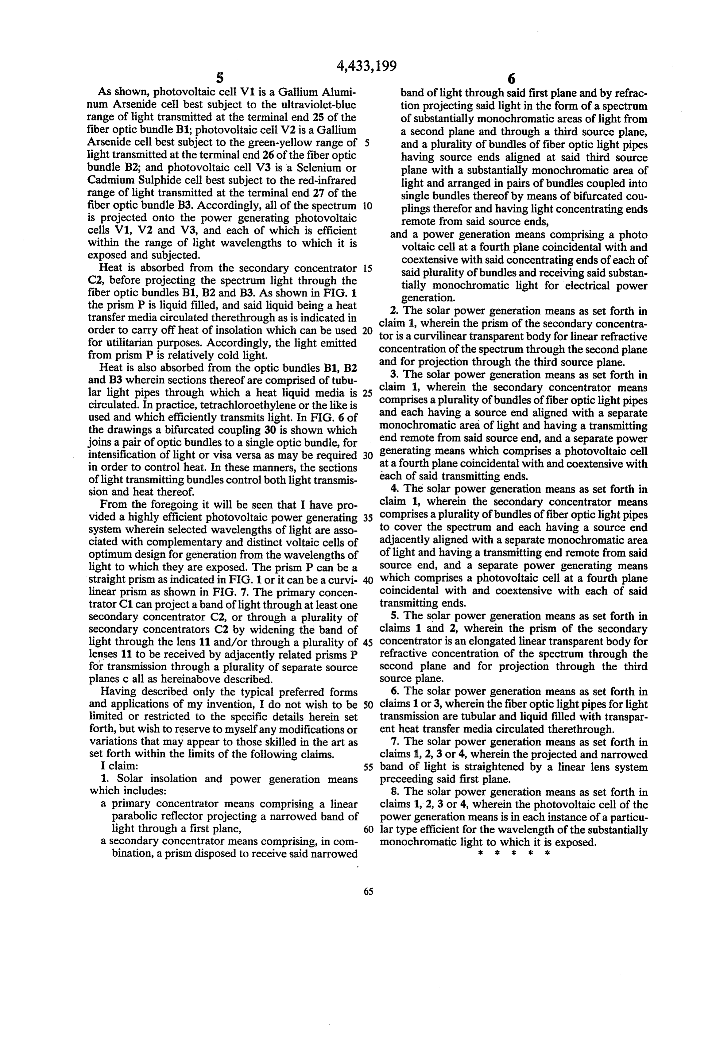
As shown, photovoltaic cell V1 is a Gallium Alumi band of light through said first plane and by refrac num Arsenide cell best subject to the ultraviolet-blue tion projecting said light in the form of a spectrum range of light transmitted at the terminal end 25 of the of substantially monochromatic areas of light from fiber optic bundle B1; photovoltaic cell V2 is a Gallium a second plane and through a third source plane, Arsenide cell best subject to the green-yellow range of 5 and a plurality of bundles of fiber optic light pipes light transmitted at the terminal end 26 of the fiber optic having source ends aligned at said third source bundle B2; and photovoltaic cell V3 is a Selenium or plane with a substantially monochromatic area of Cadmium Sulphide cell best subject to the red-infrared light and arranged in pairs of bundles coupled into range of light transmitted at the terminal end 27 of the single bundles thereof by means of bifurcated cou fiber optic bundle B3. Accordingly, all of the spectrum O plings therefor and having light concentrating ends is projected onto the power generating photovoltaic remote from said source ends, cells V1, V2 and V3, and each of which is efficient and a power generation means comprising a photo within the range of light wavelengths to which it is voltaic cell at a fourth plane coincidental with and exposed and subjected. coextensive with said concentrating ends of each of Heat is absorbed from the secondary concentrator 15 said plurality of bundles and receiving said substan C2, before projecting the spectrum light through the tially monochromatic light for electrical power fiber optic bundles B1, B2 and B3. As shown in FIG. 1 generation.
the prism P is liquid filled, and said liquid being a heat 2. The solar power generation means as set forth in transfer media circulated therethrough as is indicated in claim order to carry off heat of insolation which can be used 20 tor is a1,curvilinear wherein the prism of the secondary concentra for utilitarian purposes. Accordingly, the light emitted concentration of thetransparent spectrum body for linear refractive through the second plane from prism P is relatively cold light. and for projection through the third source plane. Heat is also absorbed from the optic bundles B1, B2 and B3 wherein sections thereof are comprised of tubu claim 1, wherein the secondary concentratorforth 3. The solar power generation means as set in lar light pipes through which a heat liquid media is 25 comprises a plurality of bundles of fiber optic lightmeans pipes circulated. In practice, tetrachloroethylene or the like is and each having a source end aligned with a separate used and which efficiently transmits light. In FIG. 6 of monochromatic area of light and having a transmitting the drawings a bifurcated coupling 30 is shown which joins a pair of optic bundles to a single optic bundle, for end remote from said source end, and a separate power intensification of light or visa versa as may be required 30 generating means which comprises a photovoltaic cell in order to control heat. In these manners, the sections at a fourth plane coincidental with and coextensive with of light transmitting bundles control both light transmis each of said transmitting ends.
sion and heat thereof. 4. The solar power generation means as set forth in From the foregoing it will be seen that I have pro claim 1, wherein the secondary concentrator means vided a highly efficient photovoltaic power generating 35 comprises a plurality of bundles offiber optic light pipes system wherein selected wavelengths of light are asso to cover the spectrum and each having a source end ciated with complementary and distinct voltaic cells of adjacently aligned with a separate monochromatic area optimum design for generation from the wavelengths of of light and having a transmitting end remote from said light to which they are exposed. The prism P can be a source end, and a separate power generating means straight prism as indicated in FIG. 1 or it can be a curvi 40 which comprises a photovoltaic cell at a fourth plane linear prism as shown in FIG. 7. The primary concen coincidental with and coextensive with each of said trator C1 can project a band of light through at least one transmitting ends.
secondary concentrator C2, or through a plurality of 5. The solar power generation means as set forth in secondary concentrators C2 by widening the band of claims 1 and 2, wherein the prism of the secondary light through the lens 11 and/or through a plurality of 45 concentrator is an elongated linear transparent body for lenses 11 to be received by adjacently related prisms P refractive concentration of the spectrum through the for transmission through a plurality of separate source second plane and for projection through the third planes call as hereinabove described. source plane.
Having described only the typical preferred forms 6. The solar power generation means as set forth in and applications of my invention, I do not wish to be 50 claims 1 or 3, wherein the fiber optic light pipes for light limited or restricted to the specific details herein set transmission are tubular and liquid filled with transpar forth, but wish to reserve to myself any modifications or ent heat transfer media circulated therethrough. variations that may appear to those skilled in the art as 7. The solar power generation means as set forth in set forth within the limits of the following claims. claims 1, 2, 3 or 4, wherein the projected and narrowed I claim: 55 band of light is straightened by a linear lens system 1. Solar insolation and power generation means preceeding said first plane.
which includes: 8. The solar power generation means as set forth in a primary concentrator means comprising a linear claims 1, 2, 3 or 4, wherein the photovoltaic cell of the parabolic reflector projecting a narrowed band of power generation means is in each instance of a particu light through a first plane, 60 lar type efficient for the wavelength of the substantially a secondary concentrator means comprising, in com monochromatic light to which it is exposed. bination, a prism disposed to receive said narrowed ik is 3:
Provenance
- Collection
- Cited prior art
- Original PDF
- patentimages.storage.googleapis.com →
- Filed
- 1982-06-17
- Pages
- 7
- Method
- pdftotext (the PDF's own text layer) + pdftoppm 300dpi page scans
- Source
- Google Patents bibliographic record
- Granted
- 1984-02-21
- Inventors
- Gerald W. Middy
- Transcribed from
- patentimages.storage.googleapis.com →