patent · US6220339
Energy system for buildings
24 April 2001
Page 1 — bibliographic record
(12) United States Patent (10) Patent No.: US 6,220,339 B1 Krecke (45) Date of Patent: Apr. 24, 2001
(54) ENERGY SYSTEM FOR BUILDINGS 4,279,241 7/1981 Himes .................................. 126/633 4,327,705 * 5/1982 Steutermann ... ... 126/585 (76) Inventor: Edmond D. Krecke, 15-17 route de 4,408,596 10/1983 Worf ............... ... 126/633 Grundhof, L-6315 Beaufort (LU) 4,444,177 * 4/1984 Kirchmayer . . 126/585 s 5,954,046 * 9/1999 Wegler ................................. 126/617 (*) Notice: Subject to any disclaimer, the term of this * cited by examiner patent is extended or adjusted under 35
U.S.C. 154(b) by 0 days. Primary Examiner Ira S. Lazarus (21) Appl. No.: 09/029,696 Assistant Examiner Tho Duong
(86) PCT No.: PCT/EP96/04009 An energy System for buildings uses Solar absorbers, heat eXchangers and heat accumulators, and has the following
S371 Date: Mar. 30, 1998 features to improve the thermal balance of the building: the Solar absorber has tubes or pipes laid to form meanders
S 102(e) Date: Mar. 30, 1998 between the roofing and an insulating layer arranged there (87) PCT Pub. No.: WO97/10474 under; the Solar absorber is Subdivided into at least two Zones each with its own liquid circulation System; there is
PCT Pub. Date: Mar. 20, 1997 arranged below the building a Solid heat-accumulator to (30) Foreign Application Priority Data which heat can be Supplied or removed using embedded tubes or pipes, the heat accumulator is Subdivided into at
Sep. 12, 1995 (DE) .............................................. 19533 475 least two Zones, i.e., a central Zone and an outer Zone each with its own liquid circulation System; during operation of (51) Int. Cl." ................................ F25B 29/00, F24J 2/40; the heat accumulator, liquid is Supplied by way of thermally F24J 2/34; E04D 13/18 controlled valves from the liquid circulation System of each (52) U.S. Cl. ......................... 165/48.2; 126/585; 126/620; Zone of the Solar absorber firstly to the liquid circulation 126/621; 126/633 System of the central heat accumulator Zone and, Secondly to (58) Field of Search ........................... 165/48.2; 126/583, the liquid circulation System of the Outer heat accumulation 126/585, 587, 617, 621, 628, 633, 634, Zone, when the temperature of the liquid in the circulation 620,597 System of the respective Zone is greater at least by one value
ranging from 2 to 8 C., preferably 2 C., than the tempera ture of the respective Solid accumulator Zone; and during
building by thermally controlled valves, firstly from the 2,342.211 * 2/1944 Newton ..... ... 126/585 liquid circulation System of the outer heat accumulator Zone 3.262,493 * 7/1966 Hervey .......... ... 126/620 and, Secondly, from the liquid circulation System of the 4,000,851 * 1/1977 Heilemann ... ... 126/633 central heat accumulator Zone.
4,129,177 * 12/1978 Adcock ......... ... 126/628 4,184,477 * 1/1980 Yuan ............. ... 126/620 4,248,209 2/1981 Wasserman .......................... 126/620 16 Claims, 5 Drawing Sheets
Page 2
Drawing sheet — no readable text.
Page 3
Drawing sheet — no readable text.
Page 4
Drawing sheet — no readable text.
Page 5
Drawing sheet — no readable text.
Page 6
Drawing sheet — no readable text.
Page 7
ENERGY SYSTEM FOR BUILDINGS absorber is divided into at least three regions, which are associated with differently oriented roof sections. This
CROSS-REFERENCE TO RELATED enables an even better separation between the different APPLICATION temperature regions to be achieved, in dependence on the Not applicable geographical orientation of the roof Sections. The tubes or pipes of the Solar absorber can Suitably be laid in troughs or
STATEMENT REGARDING FEDERALLY grooves of meandering form in the insulating layer. They are SPONSORED RESEARCH OR DEVELOPMENT then Securely mounted without additionally increasing the thickness of the insulating layer or of the roof covering.
Not applicable In an advantageous manner, the outer region of the Solid BACKGROUND OF THE INVENTION heat accumulator is widened out downward in the shape of a funnel, and the Sections which are located outside the
Field of the Invention contour of the building are covered by a heat-insulating layer. In this manner, the heat rising from the Earth's interior
The invention relates to an energy System for buildings 15 can be used to a greater extent. Even in winter, with according to the preamble of claim 1. temperatures below the freezing point, the ground is Sub Solar energy Systems have been known for a long time Stantially warmer because of the rising energy. For example, and are increasingly used for energy Saving. In particular, an average temperature at a depth of 2 m, with a free Surface, the heat produced by direct Solar irradiation is used in Solar is about +7 to +9° C. Under the building, the temperature at absorbers for the heating or preheating of Service water, and this depth amounts to at least about +14 to +16 C. The same also in heating Systems. It is also already known to first Store effect for the use of the Earth's heat results, for example, the heat energy which is not immediately required, for from covering with plantings, which prevent the Earth's example by heating water in a tank. The heat energy can rising heat from immediately radiating away again. Frost later be extracted from the accumulator by means of heat protection can be achieved in this manner. eXchangers. 25
The Solid heat accumulator can advantageously be
Heat insulation also plays an important part in the energy divided into three regions, namely the central region, a balance of a building, in addition to the energy Supply in the middle region Surrounding the central region, and an outer form of Solar energy or combustion energy. Important region Surrounding the middle region. An even finer gradu advances have been made here by heat insulating materials ation of the temperature levels of the individual accumulator in the region of the outer walls and of the roof. However, regions can thereby be attained.
further improvements of the heat balance are desirable, and The Outer region of the Solid heat accumulator can fur the invention therefore has as its object to make Such thermore be Surrounded by a peripheral accumulator region. improvements possible. The attainment of the object is The recovery of further heat energy can thereby be made characterized in claim 1. In common with other features possible. In particular, however, the peripheral accumulator which are described in more detail hereinbelow, it is based 35 can also be used to obtain cooling in the building by means on physical fundamentals. of the cold liquid.
The Solar absorber according to feature (a) is Substantially By means of the different accumulator regions, with more cost-effective than known Solar absorbers, which are respectively lower temperatures, which Surround the central installed additionally on the roof in the form of plates. By the 40 region in a Shell shape but are as far as possible open laying of tubes or pipes between the roof covering, which downward, the result is achieved that the central region is generally consists of roofing tiles, and the insulating layer, better insulated and loses leSS heat, because the Surrounding no additional constructional materials are required other middle region is leSS cold than the ground. The correspond than the tubes or pipes. Furthermore, the external appear ing relationship also holds for the outer accumulator region. ance of the building is not detracted from. 45 The lateral heat outflow of the accumulator is largely com The division of the solar absorber according to feature (b) pensated by the funnel-shaped configuration of the outer into at least two regions, each with its own liquid circuit, accumulator region. Moreover, even the Smallest Solar heat insures that the liquids heated in the absorber can be used with a lower temperature can still be used by the division of Separately according to their respective temperatures, the accumulator into Several regions, in that the liquid from instead of producing an average, mixed temperature at the 50 the Solar absorber regions is conducted into the outer or output of the Solar absorber. For example, the liquid with the peripheral region of the Solid accumulator. In this manner, higher temperature can also then further boost a heat even in winter at absorber temperatures between 8 C. and accumulator, even when the average mixed temperature is 15 C., the Solar energy can be used by loading the periph below the temperature of the heat accumulator. eral accumulator region. The “protective jacket' around the The Solid heat accumulator according to feature (c) is 55 central accumulator region is improved by heating in this likewise divided into at least two regions. The central region manner. Altogether, it is thereby possible to bridge over the then has the higher temperature. The regions with lower dreaded energy hole in the months of December through temperature can then also be further loaded by means of March in the conventional Solar heating technology. absorber liquids when their temperature is lower than that of At least a portion, or all, of the Outer walls appropriately the central region. A very good energy balance can thereby 60 each has a tube or pipe System through which liquid flows be attained. The feature (e) describes more precisely the in order to transfer heat from the wall to the liquid or vice operation controlled by temperature Sensors. Versa, wherein the tube or pipe System can be connected in Correspondingly, the feature (f) describes more precisely the a circuit with a pump for the liquid. In this manner, a heat operation by means of which heat energy is extracted from eXchange can take place between the outer walls on the Sun the accumulator regions for heating the building. 65 Side and the Shade Side. Such a "north-South equalization' Further developments of the invention are the subject of can Substantially improve the heat economy of the building the dependent claims. Thus it can be provided that the Solar when heat from the hot South wall is delivered to the cold
Page 8
north wall in Summer. This leads in winter also to a more insulating layer. An energy loSS from the regions of the heat uniform heat distribution in the building. The outer walls of accumulator which have a higher temperature than the the building can appropriately be additionally provided on ground below them is thereby hindered. In the outer region, the outside with a transparent, absorption-increasing coating and particularly in the peripheral region, heat insulation may or facing, in order to obtain a better energy yield. Such a on the contrary be inappropriate, when the heat rising from transparent heat insulation is also denoted by “TWD’. the Earth's interior arrives with a higher temperature than A further development of the invention provides for the that of the respective accumulator region. Water or an tube or pipe system of the outer walls of the building to be antifreeze agent of the usual kind is used as the liquid for all connected via temperature-controlled valves to the liquid the circuits.
circuits of the regions of the Solid heat accumulator. Then in Circulation pumps may possibly be necessary in the Summer the energy radiated in can be Stored, and further individual regions of the Solar absorber, of the Solid heat more cool liquid, in particular from the peripheral accumulator, can be Supplied for the cooling of the tube or accumulator, and of the building heating System which is pipe Systems in the Outer walls. In winter, the pipe Systems appropriately designed as floor heating or outer wall heating, of the outer walls of the building are advantageously used as 15 the circulation pumps are not described in detail here, Since a heating System. Moreover, additional heat energy can be a skilled artisan can judge without difficulty their respective recovered in winter, particularly in the case of a coating or use in each individual case.
facing with absorption-increasing material (TWD). Modem buildings are so well sealed that periodic venti The tube or pipe systems in the outer walls of the building lation is indispensable. However, this leads to heat losses, or make possible numerous air conditioning processes and to an undesired additional heat inflow in Summer. A devel compensation functions and are therefore also termed an opment of the invention proposes that openings for air “outer wall air conditioning and compensation System” interchange are provided, particularly in the window frames, (AKK system). There belong to the functions the north and heat eXchangers in them are connected to the tube or South equalization already mentioned, air conditioning in the pipe Systems of the building outer walls and have fins Summer months by taking away exceSS Solar heat, a com through which the liquid flows. The air flowing in winter can pensation for heat transmission losses in the winter months 25 by Space heating by means of Stored energy, and also the then be preheated by the heat eXchangers, with recovery of function as a wall heating System. A ring conduit can inflowing and the heat, in Summer a corresponding cooling of the air can be obtained.
suitably be laid for this purpose in a solid floor, and branch ducts can lead from it to the outer walls of the individual Another Solution of the ventilation problem proposes that Spaces. Thermostatic valves in these branch ducts permit an outer ground duct arranged around the peripheral heat individual temperature regulation of each individual Space. accumulator region and an inner intake channel running in A large-Surface heating of this kind was already known in the Solid heat accumulator are provided. Controlled by a Roman times as hypocaust heating, and Served for the multi-way valve, cooled air can be Sucked in through the heating of Villas and baths. The temperature adjustment of outer duct in Summer operation, and in winter operation historic protected buildings, with thermal drying of masonry 35 preheated air can be Sucked in through the inner duct and at the same time, is also made possible by Such a System. conducted into the building.
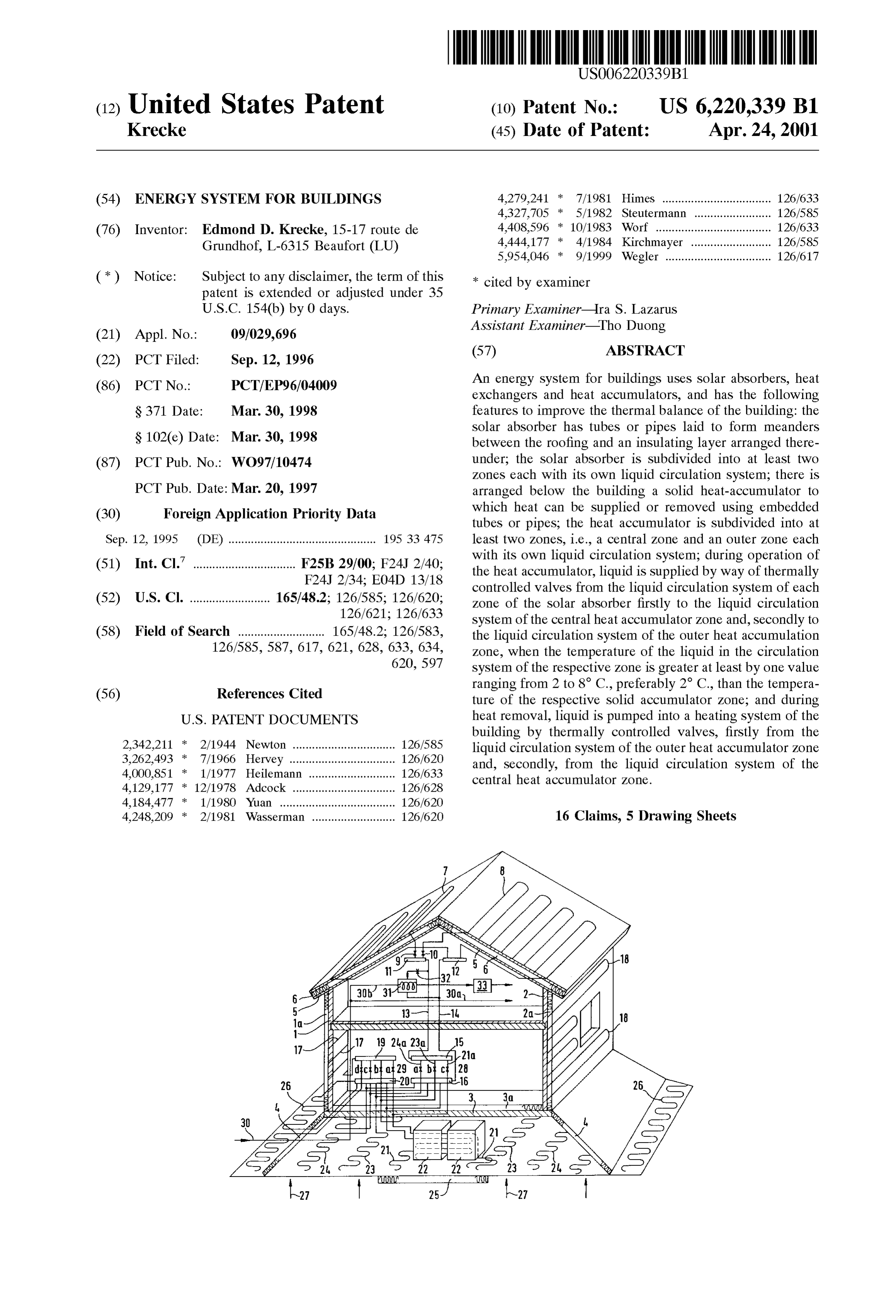
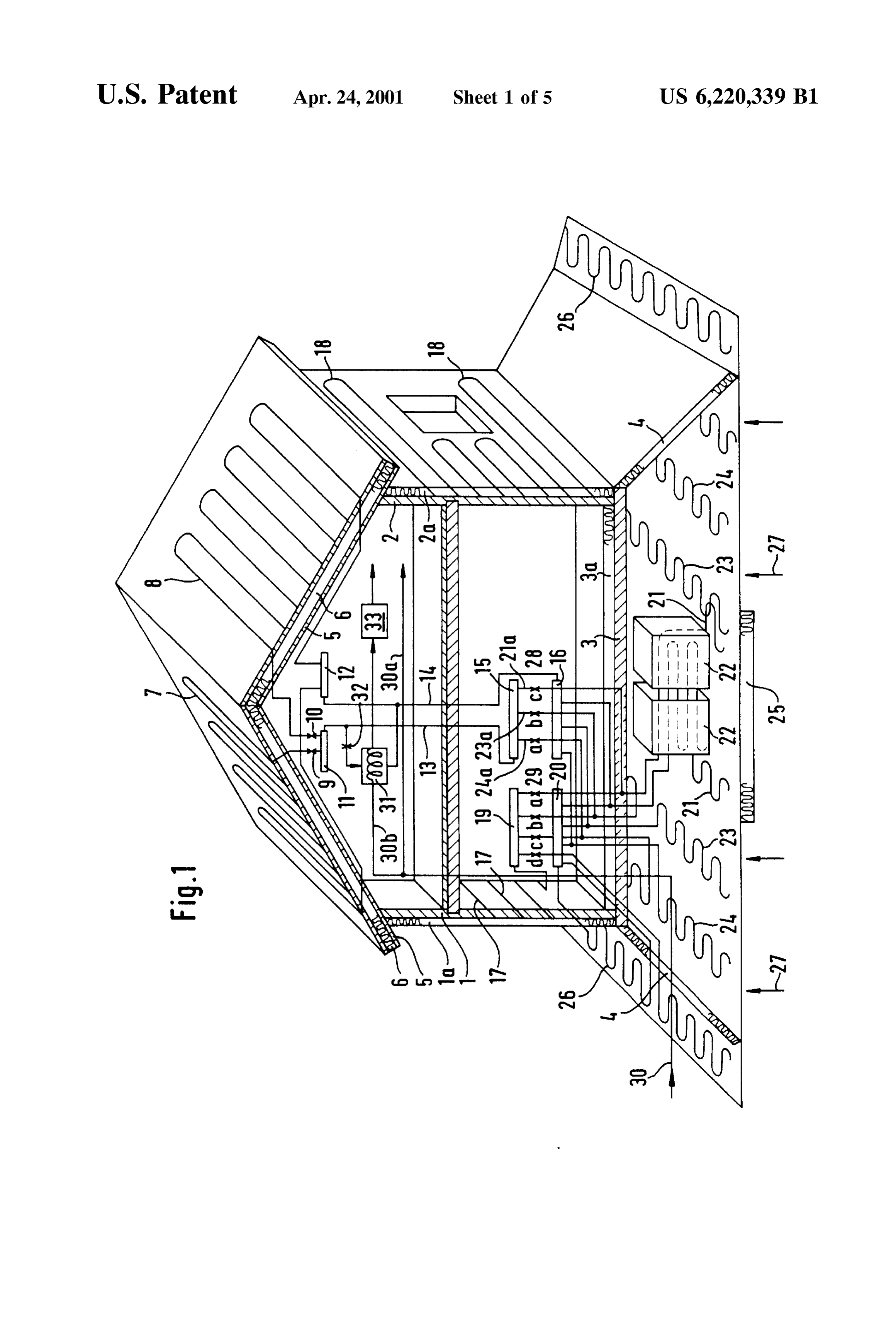
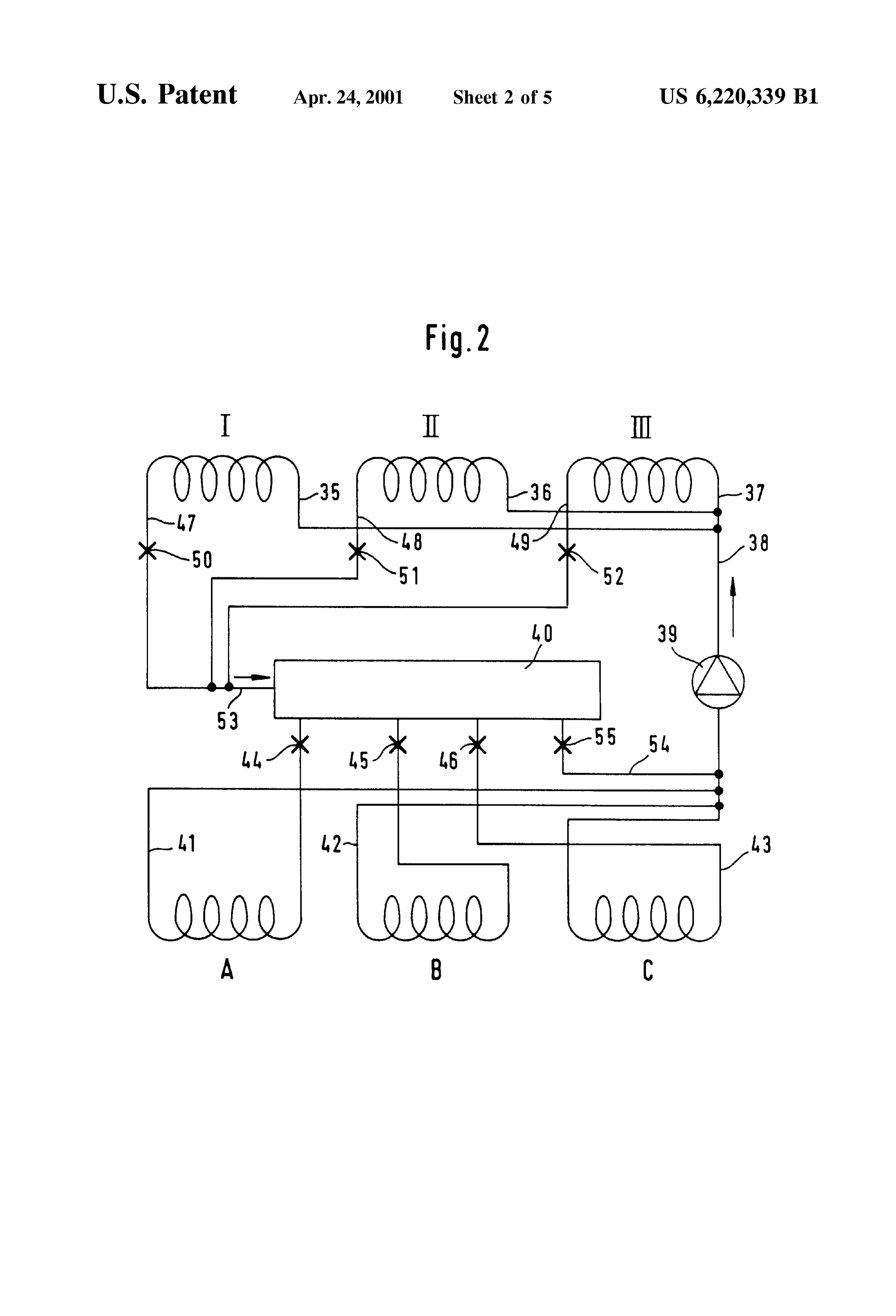
Solid accumulators may then usually be installed in the Embodiment examples are described hereinbelow with cellars of Such buildings. Solar absorbers can be retrofitted reference to the accompanying drawings. during roof repairs without externally detracting from the FIG. 1 shows schematically a building with the various appearance of the building. If necessary, Solar absorbers can 40 Systems and devices according to the invention. also be placed outside the building, or if necessary one can FIG. 2 shows a modification of the embodiment example manage without the absorber. according to FIG. 1.
The AKK System can also prevent dew point problems in FIG. 3 shows schematically a variant of the building endangered regions of Structural members, by maintaining according to FIG. 1.
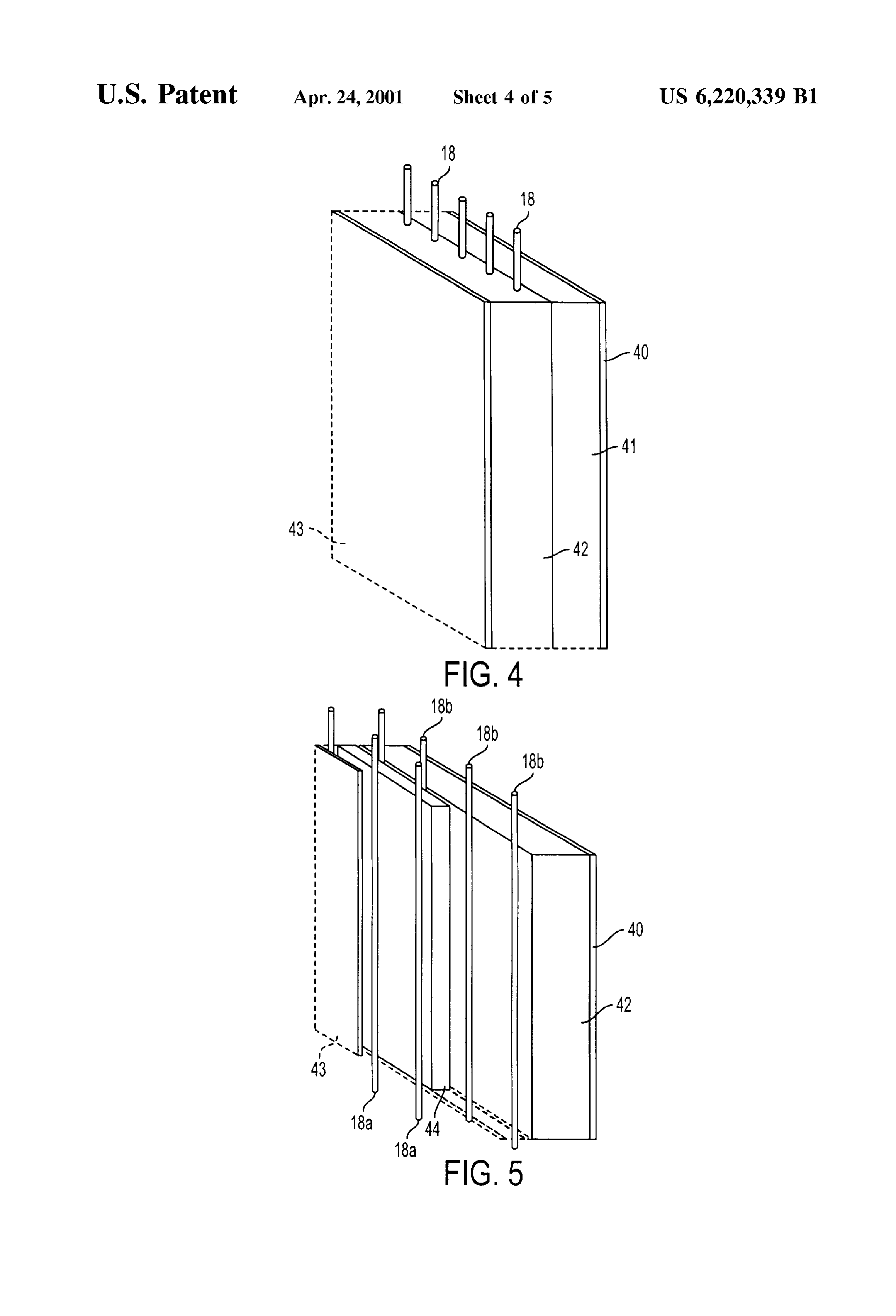
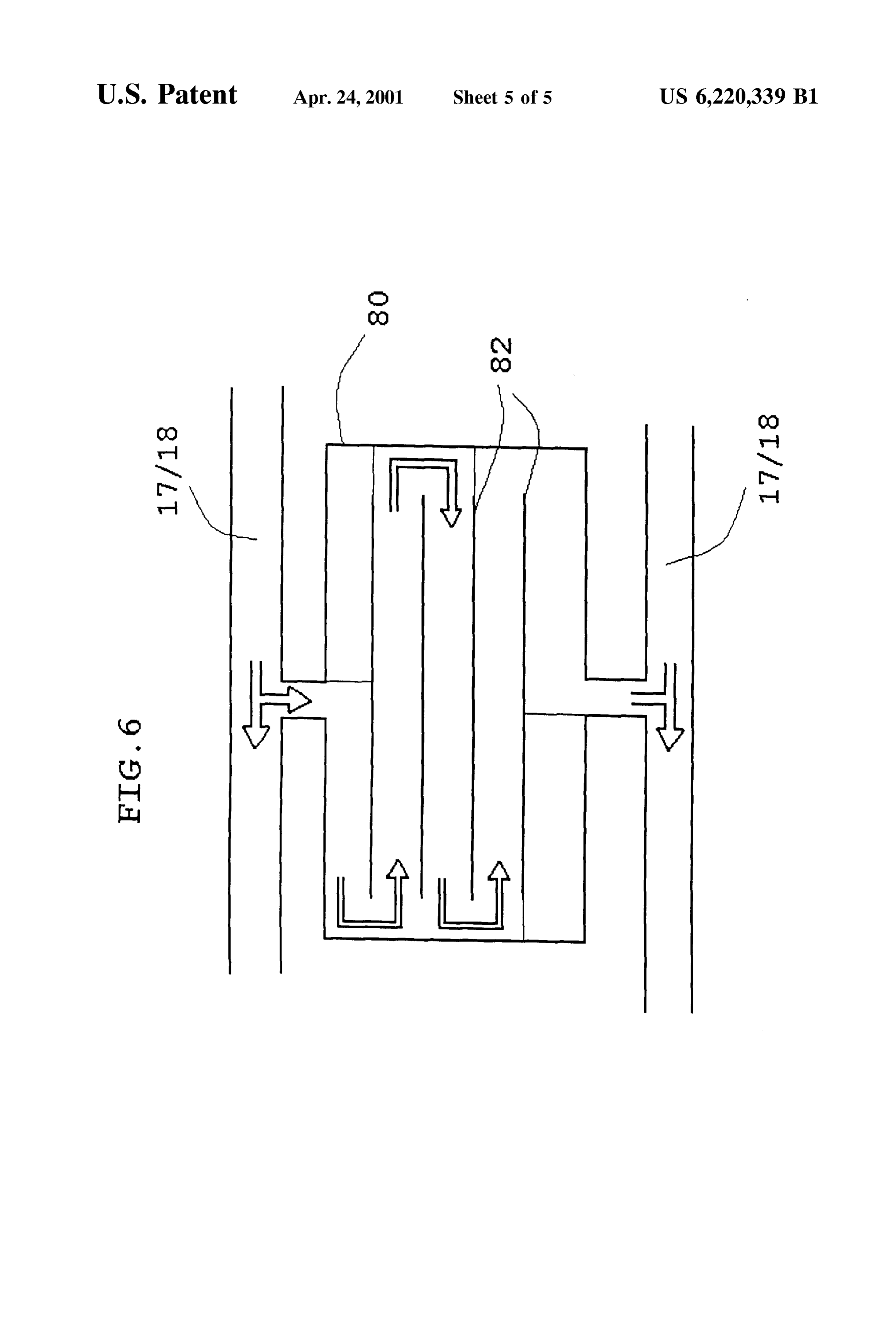
dryneSS, and by condensation protection in regions exposed 45 to high humidity or in regions in contact with the ground. FIG. 4 shows a perspective partial view of a building Finally, a low power (few kW) emergency and additional outer wall with an outer insulating layer, and heating System can be connected to the circuits of the AKK FIG. 5 shows schematically a perspective partial view of System, for extreme weather conditions, or even for habits of a building outer wall with an inner insulating layer. use which lack energy discipline and which cannot be 50 FIG. 6 shows a heat exchanger with fins connected to a calculated. first tube or pipe system of outer walls of another embodi A Service water heat eXchanger can be connected by ment of the invention.
means of temperature controlled valves, as a bypass and The outer walls 1, 2 of the house, in a concrete formwork with priority, to that region of the Solar absorber which has construction, are provided with an insulating layer 1a, 2a the highest temperature. A heating or preheating of the 55 which has, for example, a thickness of at least 25 cm and service water to more than 40 C. can be obtained in this consists of hard polystyrene foam. The bottom slab 3 of the manner. The Solid heat accumulator appropriately contains house is likewise cast from concrete and is provided with an as accumulator material a packing of broken Stone or gravel, insulating layer 3a. The heat insulating layer 4 extends from at least 60 cm thick, because of its low cost and high Specific the bottom slab and the outer walls 1, 2. Such insulating heat. In addition, in the central region of the Solid heat 60 layerS 4 are only shown in the drawing on the two sides accumulator, a layer can be formed of Steel beams, auto shown with the outer walls 1, 2. The front and back walls of cubes (old autos compressed into cubes), and Similar mate the house are however of a similar Structure. rial with the highest possible Specific heat. Disposal of Such The oblique heat insulating layerS 4 form, together with materials is thus effected at the same time, and may even be the bottom slab 3, a Space for a Solid heat accumulator, paid for. 65 which contains, for example, a crushed Stone or gravel bed The heat accumulator as a whole, or particularly its (not shown in detail) with additional accumulator bodies, as central region, can be insulated on the ground Side by a heat will later be described more exactly.
Page 9
S 6
The roof of the house contains, on the usual Substructure 62 is a multi-way valve 70, preferably provided in the 5 of wooden rafterS and possibly planks, a heat insulating building. By means of this multi-way valve 70 in connection layer 6 with a thickness of about 18 cm and made of the with the outer and inner air intake channels 60, 62 air Same material as the heat insulating layers 1a, 2a of the outer eXchanges between the outside and the inside of the building walls 1, 2. Meandering pipe ducts 7, 8 (polypropylene pipes, 5 is achieved.
20x2) are laid on the upper side of the heat insulating layer, The peripheral accumulator region has a temperature in troughs or grooves of the insulating layer 6, beneath the between +7° C. and +15° C.
roof covering (not shown) which is in the form of roof tiles, as black as possible. The pipe ducts 7, 8 form Separate liquid EXAMPLE 1. circuits on the two Sides of the house which are shown, and are connected via temperature controlled valves 9, 10 to common collectors 11, 12 for the hot or cold side of the pipe duct systems. For simplification, the valves 9, 10 are shown External temperature -4 C. Roof absorber regions: maximum +26 C.
here, as are all other valves, as a croSS on the respective duct.
Pipe ducts 13, 14 lead from the collectors 11, 12 to further 15 collectors 15, 16, which can also be integrated with the The valves 50, 51, 52, 55 remain closed; the pump 39 is collectors 11, 12 to form a unit. Switched off. Thus no heat can be delivered to the Solid heat For as complete as possible a use of the Solar energy, the accumulator with the regions A, B, C, Since the maximum circuits of the individual Solar regions can also, as an temperature of the liquid of the Solar absorber regions still alternative (not shown), be Supplied individually to Such lies below the temperature of the Solid heat accumulator collectors in the form of Short pipe pieces. The circuits then region A with the lowest temperature. open, for example, at the end walls of the collectors, So that the liquid permanently circulates, or is pumped around, in EXAMPLE 2 the circuit. Two pipes or tubes lead from the periphery of the collectors near the ends, to the further collectors 15, 16, a 25 temperature controlled valve being inserted in one of the pipes. After the opening of the respective valve, the liquid External temperature +6 C. can then (in large part) be Supplied to the appropriate Solar absorber region I: +26 C. Solar absorber regions II and III: +12 C.
accumulator region.
FIG. 2 shows a further alternative for the connections between the Solar absorber regions I, II and III. For example, The valves 44, 45, 46, 55 are opened; the pump 39 is the regions I and II can then correspond to the pipe ducts 7, Switched on. The valve 44 opens when the temperature of 8 according to FIG.1. The region III is additionally present. the accumulator
The Supply pipes 35, 36, 37 of the regions I, II, or III are temperature of theregion A is at least 2 C. below the liquid in the collector 40.
united to a common duct 38 and lead via a circulating pump 35 39 on the one hand to a collector 40 and furthermore to the EXAMPLE 3 return ducts 41, 42, 43 of the central Solid heat accumulator
C, which corresponds to the circuit 21 in FIG. 1, and also to the sections A, B, which correspond to the circuits 24 or 23 in FIG.1. The Supply pipes of the accumulator regions A, B, 40 External temperature +36 C. C are connected to the collector via temperature controlled Temperature of the roof +64 C. to +75 C. absorber regions I, II, III:
valves 44, 45 or 46. For completion of the circuits, the return pipes 47, 48 and 49 of the absorber regions I, II and III are connected via temperature controlled valves 50, 51 and 52 The valves 50, 51, 52, and 55, and also the valve 46 which to the common duct 53, which leads into the collector 40. 45 leads to the central accumulator C, are opened. The central Furthermore, a duct 54 is present between the input of the accumulator region C is then boosted with the relatively pump 39 and the collector 40. This duct contains a further high temperature of the liquid from the Solar absorber. temperature controlled valve 55. In winter operation there furthermore exists the possibility The temperature controlled valves 50, 51 and 52 are appropriately valves which are controlled by means of 50 of opening the valves 50, 51, 52 and 55 by means of relay circuits, but only for short times at intervals.
temperature Sensors and relayS. In contrast to this, thermo
Static valves which appropriately are manually Settable are Further pipe duct systems 17 or 18 are laid in meandering used for the valves 44, 45, 46. form in the outer walls 1, 2, and are connected to collectors For the explanation of different operating States, let it be 19, 20. These connections are shown only for the pipe duct assumed, for example, that the Solid heat accumulator 55 system 17. However, the pipe duct system 18 leads to the collectors 19, 20 in a similar manner. There is thus the regions have the following temperatures: possibility of a north-South heat eXchange by pumping the hotter liquid at the one Side around to the colder liquid at the other Side, and Vice versa. Furthermore, as mentioned later,
Outer accumulator region A = +16 C. to 24 C. 60 hot water from the pipe duct systems 17, 18 can be supplied Middle accumulator region B = +25° C. to 34° C. from the pipe duct systems 17, 18 to the solid accumulator, Central accumulator region C = +35 C. and higher. or cold water for cooling can be pumped into the pipe
An outer air intake channel 60 passes around the building. The Solid accumulator is divided into a total of four An inner air intake channel 62 preferably lies within the 65 regions with different temperature ranges. The central outlines of the outer air intake channel 60. Connected to the region, which is defined by meandering pipe ducts 21 outer air intake channel 60 and the inner air intake channel imbedded in the material of the Solid accumulator and
Page 10
forming a closed circuit, has additional metal packets 22, The possibility also exists, however, of controlling all the with a protective layer, in the crushed rock or gravel bed, Valves centrally by means of a computer according to a with the pipe ducts 21 likewise passing through them or predetermined program, by means of relays or Servomotors. around their Surfaces. As a result, the central region 21, 22, Maximum flexibility is thereby obtained under different which has the highest accumulator temperature, also has a weather conditions and weather changes.
raised heat capacity. The imbedding of the pipe ducts FIG. 3 shows a section through a building similar to that appropriately takes place with an intermediate or protective in FIG. 1. The essential components including the roof absorber, the Solid accumulator, the wall circuits, the col layer (not shown) of concrete or the like material. The solid lectors accumulator has a middle region which is adjacent to the and the connecting pipe ducts are the same. However, central region and which is defined by a liquid circuit with the illustration in FIG. 3 corresponds more exactly to the actual conditions in a building. In particular, it should be pipes 23 running in a meandering form, and an outer region noticed which surrounds the middle region 23 and is defined by a Space andthat the additional components require only a little do not Substantially complicate the construction of liquid circuit with meandering pipes 24. The pipes 23, 24 are the building.
imbedded, with a protective layer, in the crushed rock or shown, with The Solid accumulator is only Schematically gravel bed. A heat insulating layer is located beneath the 15 regions. In practice,central, the middle, outer and peripheral the central region has a temperature of central region 21, 22, and prevents heat losses in a down ward direction from the relatively hot, central region 21, 22. 38 C. and more, the middle region a temperature between 25 and 34 C., the outer region a temperature between 15
The Outer accumulator region 24 is Surrounded by a and 24 C., and the peripheral region a temperature between peripheral accumulator region with a liquid System of pipes 7 and 14 C.
26 laid in a meandering form. The peripheral region 26 FIG. 4 shows schematically the construction of an outer collects the Earth's heat (geothermal energy), which is wall with an outer plaster layer 40, an outer insulating layer symbolized by arrow 27, as do the further regions of the 41 with a thickness of between 10 and 25 cm, a Solid wall Solid accumulator. In particular, the peripheral region 26 42 of, for example, lightweight concrete, and in the interior can, however, also be used in Summer to feed cool liquid to of the building with a particle board covering 43, which can the outer wall pipe systems 17, 18 for cooling of the 25 already be suitable for wallpapering. The pipes or tubes 18 building. run in the Solid wall 42 and make heating or cooling According to FIG. 1, the distribution of the heated liquid possible, according to the above description. coming from the solar absorbers 7, 8 to the individual FIG. 5 shows a wall section of a building, for example a accumulator regions takes place by means of the collectors historic, protected building, the exterior facade of which 15, 16. Temperature controlled valves 28a, b, c are respec cannot be altered. The existing Solid wall has an existing or tively arranged in the pipe ducts 21a, 23a, 24a, which feed renewed plaster layer 40. The return pipes 18b of the pipe or liquids to the accumulator regions 22 or 23 or 24. When the tube system 18 are laid on the inner side of the solid wall 42. temperature of the liquid coming from the Solar absorber is An insulating layer 44 then results from the filling (not high, for example, between 25 C. and 35 C., the liquid is 35 shown) of the interspaces between the pipes 18b, and on it then supplied via the valve 28c to the central accumulator are laid the inlet pipes 18a, offset relative to the return pipes with the liquid circuit 21. When the temperature is between 18b, and possibly in grooves (not shown). An inner wall 15 and 24 C., for example, the middle/outer accumulator lining 43 forms a completion. The heating of the internal region 23 is loaded. Finally, the hot liquid is Supplied to the Spaces then takes place by means of the Supply pipes 18a as outer Storage region 24 when the temperature is between 7 40 a wall heating, and the return pipes 18b make possible a and 14 C., for example. heating of the outer Solid wall 42, Such that a thermal drying Heat can be Supplied from the accumulator regions 21, 23, and maintenance of dryneSS is made possible. 24, 26 by means of collectors 19, 20 via valves 29a, b, c, d FIG. 6 schematically shows a heat exchanger 80 with fins to the outer wall liquid systems 17 and 18 for the heating of 82, which is connected to a first tube or pipe system 17, 18. the building. The valves 29a, b, c, d are likewise temperature 45 The arrows in FIG. 6 indicate the directions of the airflow. controlled, so that the systems 17, 18 are respectively acted In this drawing air flows from the right side of the tube or on with a liquid of the required temperature. In Summer, pipe 17, 18 to the left side thereof. The air flow essentially there is also the possibility of feeding cold liquid from the passes the heat eXchanger 80, as indicated by the three accumulator 26 to the systems 17, 18 via the valve 29d. curved arrows; leaving the lower tube or pipe 17, 18 in the Drinking water is Supplied in the building by means of a 50 left direction.
duct 30 which feeds the consumer via a branch duct 30a. A Captions on FIG. 3 left to right further duct 30b leads to a heat exchanger 31 which is only Peripheral accumulator . . . outer accumulator . . . middle shown Schematically. This heat eXchanger is Supplied in the accumulator . . . central accumulator . . . middle bypass with hot liquid by means of a temperature controlled accumulator . . . outer accumulator . . . peripheral accumu valve 32 from the collector 11. The water flowing through 55 lator.
can thereby be heated or preheated to a temperature of 38 I claim:
C., for example. A Subsequent boiler or throughflow heater 1. An energy System for building, comprising: provides for holding a reserve, and possible further heating (a) a solar absorber having first tubes or pipes (7,8) that of the preheated Service water. Instead of the heat eXchanger are laid between a roof covering and an insulating layer 31, ducts (not shown) imbedded in the central accumulator 60 (6) arranged under said roof covering, region, in the form of polyethylene pipes, for example, can (b) said solar absorber being divided into at least two also be used. The central accumulator region then acts as a regions, each with its own liquid circuit through Said heat eXchanger. first tubes or pipes (7,8), All the valves shown can be thermostatic valves which (c) a Solid heat accumulator (21, 22, 23, 24, 26) arranged can be set manually to the desired temperature, and in fact 65 under the building, to which heat can be Supplied and Such that the valves open at the beginning of a Settable from which heat can be withdrawn by second tubes or temperature range, and close again at the end of the range. pipes laid in Said Solid heat accumulator,
Page 11
characterized in that 12. The energy System according to claim 1, in which Said Solid heat accumulator is divided into at least water or an antifreeze agent is used as Said liquid. two regions, comprising a central region (21, 22) 13. The energy System according to claim 11, in which and a middle/outer (23, B; 24) region, each with Said Solid heat accumulator is insulated in Said central region its own liquid circuit through Said Second tubes or (21) of Said Solid heat accumulator.
pipes of that region, in which 14. The energy System according to claim 1, in which Said in heat accumulation operation, liquid is Supplied via temperature of liquid from Said liquid circuit of Said respec first temperature controlled valves (9, 10) from tive solar absorber is higher by 4 than the temperature of Said liquid circuit of each region of Said Solar Said respective Solid accumulator region.
absorber primarily to said liquid circuit (21) of 15. An energy System for buildings, comprising: Said central heat accumulator region and Second (a) a solar absorber having first tubes or pipes (7,8) that arily to said liquid circuit (23, 24) of said middle/ are laid between a roof covering and an insulating layer Outer heat accumulator region, when the tempera (6) arranged under said roof covering; ture of liquid from Said liquid circuit of a (b) said solar absorber being divided into at least two respective Solar absorber region is higher at least regions, each with its own liquid circuit through Said by a value in the range of 2-8 C. than the 15 first tubes or pipes (7,8);
temperature of a respective Solid accumulator (c) a Solid heat accumulator (21, 22, 23, 24, 26) arranged region (21, 22, 23, 24, 26), and under the building, to which heat can be Supplied and in that in heat extraction operation, liquid is pumped into a heating system (17, 18) of said building from which heat can be withdrawn by second tubes or through Second temperature controlled valves pipes laid in Said Solid heat accumulator, (29a, b, c), primarily out of said liquid circuit of characterized in that
Said Solid heat accumulator is divided into at least
Said middle/outer heat accumulator region (23,24) two regions, comprising a central region (21, 22) and Secondarily out of Said liquid circuit of Said central heat accumulator region (21), and and a middle outer (23, B; 24) region, each with its in that Said Solid heat accumulator is divided into 25 own liquid circuit through Said Second tubes or three heat accumulator regions, including a middle pipes of that region, in which in heat accumulation region (23, B) that Surrounds said central region operation, liquid is Supplied via first temperature (21, C), and an outer region (24, A) that Surrounds controlled valves (9,10) from said liquid circuit of said middle region (23, B). each region of Said Solar absorber primarily to Said 2. The energy System according to claim 1, in which said liquid circuit (21) of Said central heat accumulator Solar absorber is divided into at least three regions that are region and Secondarily to said liquid circuit (23, asSociated with differently oriented roof Sections. 24) of Said middle/outer heat accumulator region, 3. The energy System according to claim 1, in which said when the temperature of liquid from Said liquid first tubes or pipes (7,8) are laid in meandering troughs or circuit of a respective Solar absorber region is grooves of Said insulating layer (6). 35 higher at least by a value in the range of 2-8 C. 4. The energy System according to claim 1, in which said than the temperature of a respective Solid accu outer region (24, A) of Said Solid heat accumulator is mulator region (21, 22, 23, 24, 26), and widened downward in a shape of a funnel and, outside a in that in heat extraction operation, liquid is pumped contour of Said building, is covered by a heat insulating layer into a heating system (17, 18) of said building (4). 40 through Second temperature controlled valves 5. The energy System according to claim 1, in which said (29a, b, c), primarily out of said liquid circuit of outer region (24, A) of Said Solid heat accumulator is Said middle/outer heat accumulator region (23,24) Surrounded by a peripheral accumulator region (26). and Secondarily out of Said liquid circuit of Said 6. The energy System according to claim 1, in which third central accumulator region (21), tube or pipe systems (17, 18) through which liquid flows are 45 further comprising an outer air intake channel contained in at least a portion of outer walls (1, 2) of Said arranged around a peripheral accumulator region building. (26) and an inner intake channel running in Said 7. The energy System according to claim 6, in which said Solid heat accumulator (21, 23, 24), and a multi third tube or pipe system (17, 18) is connected via sixth of way valve for controlling cooled air that can be temperature controlled valves (29a, b, c, d) to liquid circuits 50 Sucked in through Said outer air intake in Summer (21, 23, 24, 26) of said Solid heat accumulator region. operation, and preheated air that can be Sucked in 8. The energy System according to claim 6, in which said through an inner intake channel in winter opera building outer walls (1, 2) are provided on an outside with tion and be blown into said building. an absorption-increasing, transparent coating (TWD) or 16. An energy System for buildings, comprising: facing. 55 (a) solar absorber having first tubes or pipes(7,8) that are 9. The energy System according to claim 1, in which a laid between a roof covering and an insulating layer (6) Service water heat exchanger (31) is connected via a seventh arranged under Said roof covering, temperature controlled valve (32) as a bypass and with (b) said solar absorber being divided into at least two priority to a region (7,8) of said solar absorber that has regions, each with its own liquid circuit through Said highest temperature. 60 first tubes or pipes (7,8), 10. The energy System according to claim 1, in which said (c) a Solid heat accumulator (21, 22, 23, 24, 26) arranged Solid heat accumulator contains as accumulator material a under the building, to which heat can be Supplied and crushed rock or gravel packing with a thickness of at least from which heat can be withdrawn by second tubes or 60 cm. pipes laid in Said Solid heat accumulator, 11. The energy System according to claim 1, in which said 65 characterized in that
Solid heat accumulator is insulated on a ground Side by a Said Solid heat accumulator is divided into at least heat insulating layer (25). two regions, comprising a central region (21, 22)
Page 12
and a middle outer (23, B; 24) region, each with its and Secondarily out of Said liquid circuit of Said own liquid circuit through Said Second tubes or central heat accumulator region (21), and pipes of that region, in which in that said solar absorber regions (I, II, III) are in heat accumulation operation, liquid is Supplied via brought together on their return side (47, 48, 49) first temperature controlled valves (9, 10) from by means of third temperature controlled valves Said liquid circuit of each region of Said Solar (50, 51,52) and feed a collector (40) in common; absorber primarily to said liquid circuit (21) of and united return sides (41, 42, 43) of said central Said central heat accumulator region and Second Solid accumulator region (21, C) and united return arily to said liquid circuit (23, 24) of said middle/ Sides of Said middle/outer Solid accumulator Outer heat accumulator region, when the tempera region (23, B, 24, A) are Supplied in common via ture of liquid from Said liquid circuit of a a pump (39) to a supply side of said solar absorber respective Solar absorber region is higher at least (35, 36,37); and Supply sides of said central solid by a value in the range of 2-8 C. than the accumulator region (C) and said middle/outer temperature of a respective Solid accumulator
Solid accumulator region (A,B) open into Said collector (40), via a fourth temperature controlled region (21, 22, 23, 24, 26), and 15 valve (44, 45, 46) respectively; and a connection in that in heat extraction operation, liquid is pumped (54) is provided via a fifth temperature controlled into a heating system (17, 18) of said building valve (55) between an inlet of said pump (39) and through Second temperature controlled valves said collector (40).
(29a, b, c), primarily out of said liquid circuit of
Said middle/outer heat accumulator region (23,24) k k k k k
Provenance
- Collection
- Cited prior art
- Original PDF
- patentimages.storage.googleapis.com →
- Filed
- 1996-09-12
- Pages
- 12
- Method
- pdftotext (the PDF's own text layer) + pdftoppm 300dpi page scans
- Source
- Google Patents bibliographic record
- Granted
- 2001-04-24
- Inventors
- Edmond D. Krecke
- Transcribed from
- patentimages.storage.googleapis.com →