patent · US4227939
Luminescent solar energy concentrator devices
14 October 1980
Page 1 — bibliographic record
United States Patent (19) 11) 4,227,939 Zewail et al. 45 Oct. 14, 1980 54) LUMNESCENT SOLAR ENERGY (56) References Cited CONCENTRATOR DEVICES U.S. PATENT DOCUMENTS 3,934, i48 1/1976 Collins ............................... 350/96 R (75) Inventors: Ahmed H. Zewail; J. Samuel 4,029,519 6/1977 Schertz et al. .................. 136/89 PC Batchelder, both of Pasadena, Calif. 4,110,123 8/1978 Goetzberger ................... 136/89 HY 4,127,425 11/1978 Chambers ........................ 136/89 PC 4,130,445 12/1978 Blieden ...... . 136/89 PC (73) Assignee: California Institute of Technology, 4,140,544 2/1979 Sill .............. 136/89 PC Pasadena, Calif. 4,149,902 4/1979 Mauer et al. ................ 136/89 PC 21 Appl. No.: 1,585 Primary Examiner-Aaron Weisstuch Attorney, Agent, or Firm-Poms, Smith, Lande & Rose 22 Filed: Jan. 8, 1979 57 ABSTRACT Increased light output is achieved from a solar energy 51 Int. C. ............................................. H01L 31/04 concentrator light piping device by rendering the top (52) U.S. C. .................................... 136/247; 136/259; surface of the device concave, and/or forming the de 250/227; 250/361 R; 250/367; 250/483; vice into a close-packing hexagonal shape and/or curv 350/96.1; 350/96.34 ing and applying a mirror coating to the output edge of 58) Field of Search ........ 136/89 FC, 89, CA, 89 CL; the device.
350/96.1, 96.34 14 Claims, 12 Drawing Figures
Page 2
Drawing sheet — no readable text.
Page 3
Drawing sheet — no readable text.
Page 4
Drawing sheet — no readable text.
Page 5
Drawing sheet — no readable text.
Page 6
Drawing sheet — no readable text.
Page 7
tions between the dyes could take place, greatly increas
LUMNESCENT SOLAR ENERGY ing the overall collection efficiency. Each dye will CONCENTRATOR DEVICES absorb the solar flux within its absorption band. The emission of this dye is absorbed by a different dye, form
BACKGROUND OF THE INVENTION 5 ing the so-called photon cascade. The device has been 1. Field of the Invention designated as the multiple dye Planar Solar Collector The present invention relates to luminescent solar (PSC), The which is an extension of the single dye PSC.
principle advantages of the LSC or PSC is its energy concentrator devices and more particularly, to configurational improvements in a multiple-dye con 10 low initial cost and indifference to solar angle of inci taining luminescent solar concentrator (LSC). dence. It should be noted though that while the LSC is 2. Description of the Prior Art a high gain collector it is also a lossy collector. A frac Ground level solar energy radiation is so dilute that tion of the photon's energy is dissipated in the cascade devices which concentrate sunlight are utilized before process, and this fraction would be waste heat for converting it to electrical or thermal energy. These photothermal collection. Because of this the primary devices typically use geometric optics in the form of application will be in photovoltaic conversion. Efficient mirrors and lenses. In doing so they incur the problems photovoltaic cells (PVC) are costly, and hence will of cost and the requirement of tracking. Optics with benefit most dramatically from the high geometric gains high concentration capabilities need to track or be re possible in an LSC; in fact, their efficiency increases directed towards the sun on an hourly basis, while even 20 with such high flux levels. Further, waste energy usu moderate gain devices require adjustments for seasonal ally dissipated in the PVC is released in the LSC matrix, changes. Design tolerances and good weathering capa reducing the cell's operating temperature. bility, as well as the need for tracking, make a geometri The present invention relates to geometric improve cal optics concentrator an expensive alternative. ments designed to provide increased and uniform out A promising new type of solar collector, the Lumi put of light at the edge of luminescent solar concentra nescent Solar Concentrator (LSC), has recently been 25 tors.
proposed based on light-pipe trapping of molecular SUMMARY OF THE INVENTION fluorescence. Conceptually, the concentrator process proceeds as follows: the solar flux passes into a transpar An isotropic distribution of dye molecules in a planar ent substrate such as a flat plate which has an index of 30 LSC allows typically about 26% of the luminescence to refraction greater than that of air. The solar photons are be lost out of the face of the LSC via the critical cone. absorbed and subsequently randomly reemitted in all It should be noted that the final performance of the directions by fluorescence of an efficient fluorescent LSC is governed by a relatively high power of the dye. Snell's law dictates that a large fraction, typically critical cone loss. Studies of self-absorption show that if 75%, of this reemission strikes the surface of the sub 35 P is the probability that luminescence will be lost out of strate with an angle of incidence greater than the criti the critical cone, that the complete LSC system perfor cal angle, so that this fraction of the light is then trapped mance will scale as (1-P)N, where N is typically some in the substrate by internal reflection until successive number close to 4. For this reason, it is extremely im reflection carries it to the edge of the plate where it portant to reduce the critical cone as much as possible. enters an absorber placed at the edge of the plate. If 40 In accordance with the invention, it has been discov light enters the face of area Afand leaves via an edge of ered that if the surface of the LSC exposed to solar area Ae, the net geometric gain Ggeom is: radiation is made convex the critical cone area pointing Gigeom=Af/Ae (I) upwardly is squeezed down, reducing the critical cone loss by 30% using a one-dimensional concave ripple and
Of the proposed solar-energy technologies, photovol 45 by an additional 30% using a two-dimensional concave ripple.
taic conversion offers the unique advantages of direct conversion of photons to electrical energy combined to The critical cone loss mechanism can also be utilized increase the gain at the edge of the LSC device.
with simplicity, low maintenance, and high redun dancy. Important problems related to the improvement Because of this loss, the light emerging from the edge of photovoltaic conversion efficiency are (a) how to 50 and incident on a photo-voltaic cell (PVC) attached to maximize the fraction of the solar spectrum collected aessentially typical planar LSC is not isotropic, i.e., there will be no flux within the critical cones emanating and (b) how to improve the methods for coupling solar photons to the photovoltaic junction. The LSC can from a point on the PVC. The remaining luminescence potentially aid in the solution of both (a) and (b). Impor can be concentrated by curving the edge, suitably into a tant advantages of the LSC collector are: it does not 55 truncated ellipse, and mirroring the curved surfaces. have to be steered to track the sun; it is nearly as effi This increases gain without incurring losses from trans cient in diffuse as in direct sunlight; it reduces heat porting the light through longer path lengths in the dissipation in the edge-mounted solar cells, since the matrix. In polymethylmethacrylate (PMMA) this will excess energy of the short-wavelength photons is dissi provide an additional gain factor of 1.35 with an ex pated over the entire area of the LSC. posed mirror length of 0.78 times the plate thickness. A series of such concentrators, each containing a A common problem in photovoltaic power genera different dye and attached to a different type of solar tion is that the performance of a number of cells in series cell, can be stacked in such a way that the solar spec will be that of the most inefficient cell in the series. By trum could be sorted and routed to a variety of photo inefficient is meant the cell that generates the least voltaic devices. It also has been shown that if a number 65 amount of current. Typically, this is partially circum of properly selected dyes were placed within the same vented by operating the cells in parallel instead of in substrate, that not only did the absorption band increase series; however, this causes problems in that the result but that radiative and non-radiative transfer of excita ing high currents generate ohmic losses. The general
Page 8
practice has therefore been to always match as closely as polycarbonate or acrylic ester polymers such as as possible the output of all the cells in an array. polymethylmethacrylate (PMMA). This problem leads to an important consideration in The matrix material is in optical communication with the design of an LSC. The output light intensity on all luminescent absorbers such that light entering the rib attached PVCs should be as nearly constant as possible. bon is absorbed by the luminescent absorbers and ree From group theory there are two planar geometries mitted within the ribbon. The luminescent absorbers where this is guaranteed to be true: one is an infinite must have a uniform concentration per unit area. The ribbon; and the other is a disc. In a rectangular slab absorbers can either be uniformly dispersed throughout LSC, the cells near the corner receive the least light and the volume of the ribbon matrix or can be applied to as have the poorest performance while a disc plate cannot O a layer to the back surface of the ribbon. The lumines be closely packed in a plane. It has further been discov cent absorbers should have a high quantum efficiency of ered according to this invention if an approximation to luminescence greater than 50%, usually greater than the disc is used, namely a hexagon, adequately uniform 90%. The absorbers can be inorganic ions such as chro illumination can be achieved all around the edge, while mium, neodymium or itrium dispersed in glass or or gaining the ability to close-pack the LSC elements in a 15 ganic fluorescent dyes dispersed in a plastic matrix, plane. The light level varies less than 5% over 75% of usually organic laser dyes having high quantum effi the edge of a hexagonal LSC which is quite satisfactory ciency, high stability, and being very highly purified. for photovoltaic conversion. The dyes are usually present in a concentration of from An optimum LSC device according to the invention 10-2 to 10-5 Molar. The concentration of each dye is is composed of an array of hexagonal, hemispherical 20 chosen such that each dye has the same peak optical sections forming a two-dimensional concave ripple and density. Since the absorption level of a single absorber having curved, mirrored ellipical output edges to which such as Rh-6G only covers a small fraction of a visible are attached PVC devices connected in combinations of spectrum, the ratio of surface area to the edge area must parallel and series. be made extremely large, i.e., about 103 to achieve good These and many other features and attendant advan 25 overall photon flux. This problem can be overcome by tages of the invention will become apparent as the in coupling or cascading the fluorescence of one dye to vention becomes better understood by reference to the the absorption of another. In fact by selecting the right following detailed description when considered in con set of dyes, it is feasible to absorb nearly all of the visible nection with the accompanying drawings. spectrum of the sun. Provided efficient energy transfer 30 occurs, the device will emit in a narrow band near the
BRIEF DESCRIPTION OF THE DRAWINGS
wavelengths of a maximum efficiency of the photovol
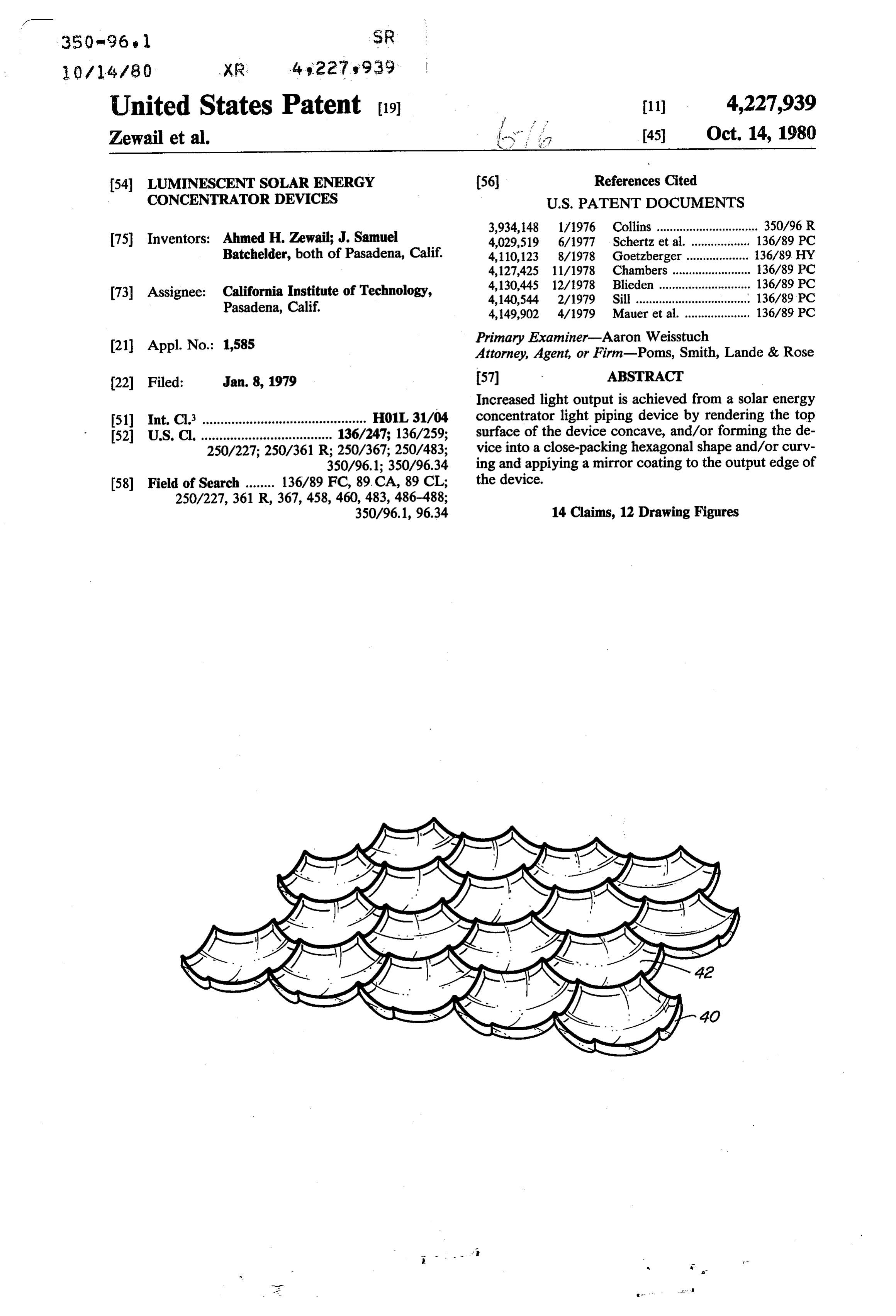
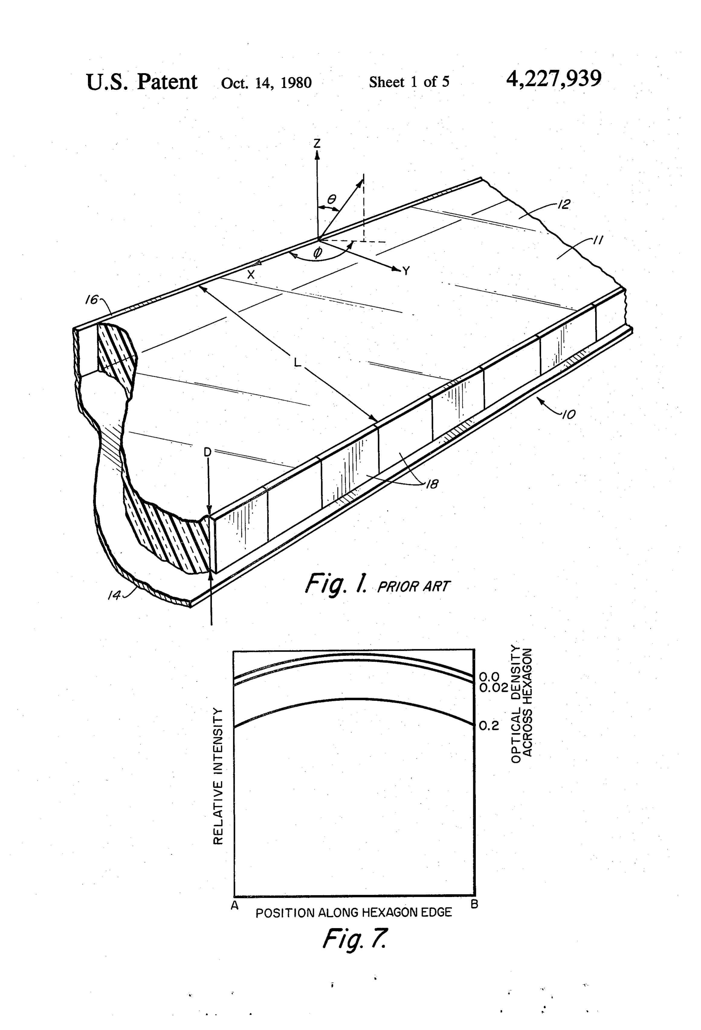
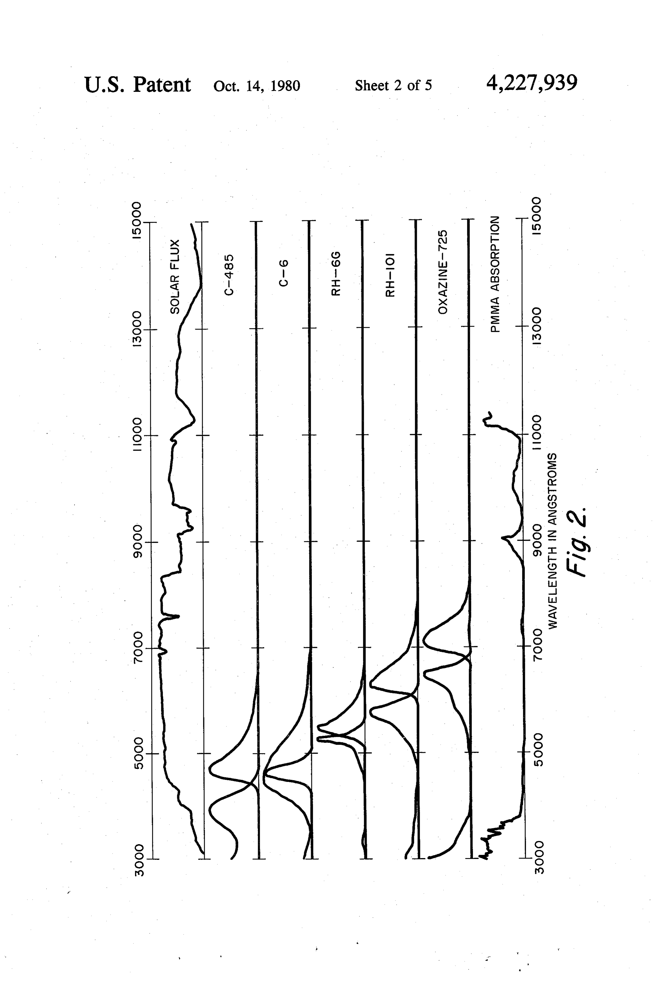
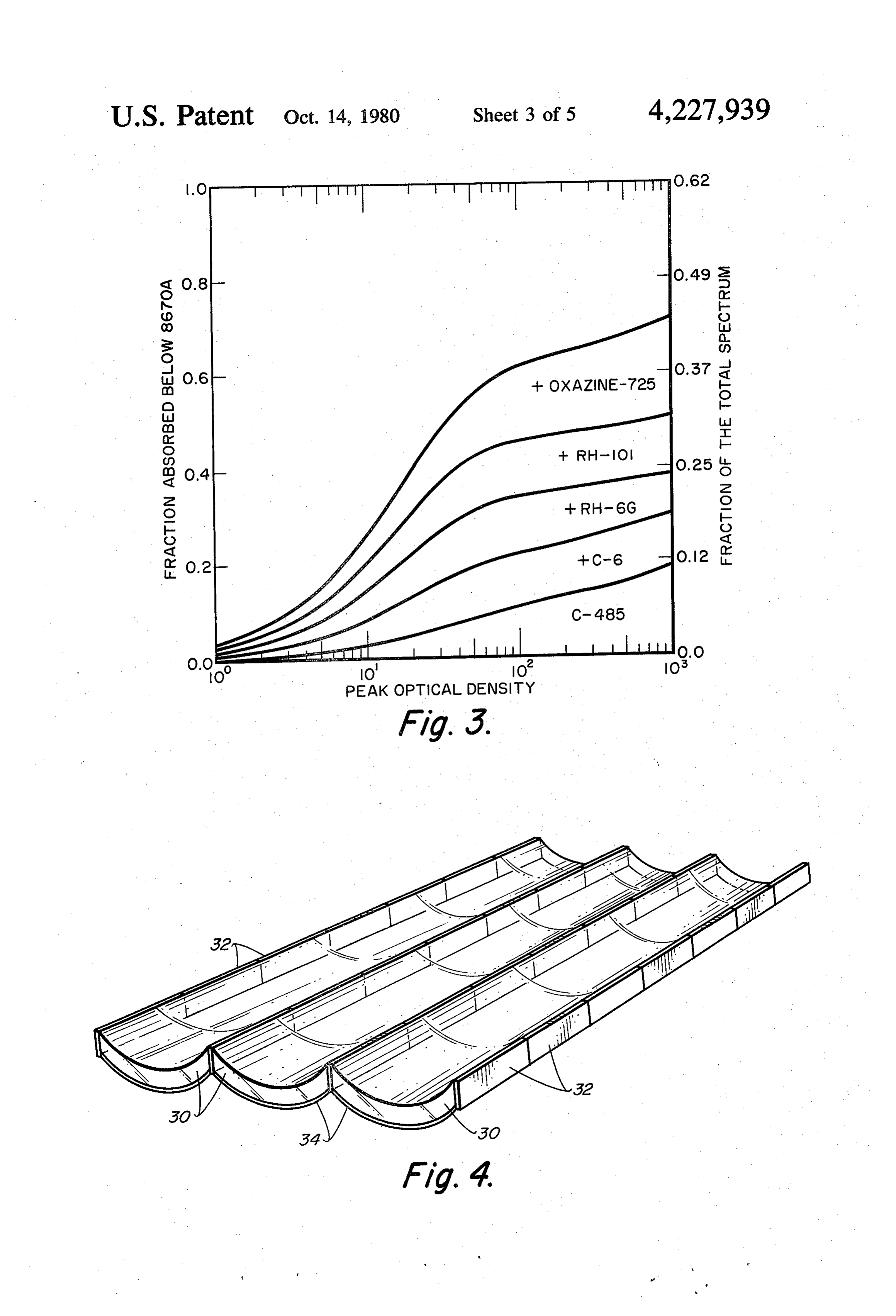
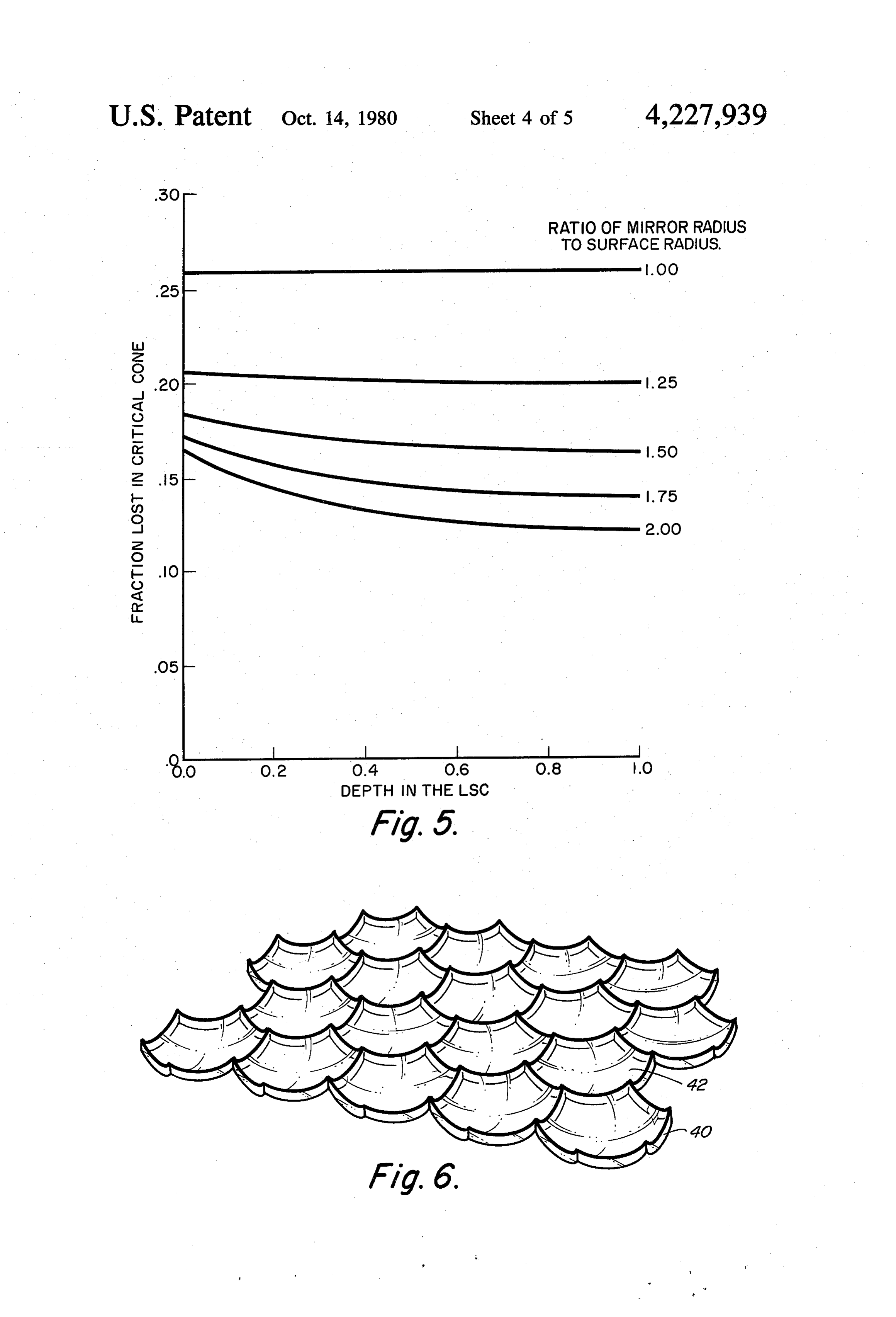
FIG. 1 is a schematic, perspective view of a prior art taic cell. Planar solar concentrators of PMMA doped PSC, with dyes are cast from solutions of the dye in mono FIG. 2 is a series of absorption spectra of a typical mer, usually in absence of solvent. The concentrators five-dye cascade shown with the solar spectrum and 35 which have good optical quality are then sanded to size PMMA absorption; and the edges polished. Preferably, at least 5 dyes are FIG. 3 is a series of graphs showing fraction of the utilized to provide a very broad, efficient absorption solar flux absorbed for a one to five-dye LSC; band for the device. The dyes are chosen such that the FIG. 4 is a schematic, perspective view of a single first dye has the highest energy of luminescence in the ripple, cylindrical LSC; spectrum and the last dye has the lowest. Each dye's FIG. 5 is a series of curves showing critical cone loss emission spectrum overlaps the absorption band of the for different convex single curvature ripple cylindrical succeeding dye. The absorption spectrum of a five dye LSC's; cascade device is shown in FIG. 2, along with the solar FIG. 6 is a schematic, perspective view of a double flux spectrum and the absorption spectrum for PMMA. ripple, hexagonal LSC shown in a planar array; 45 As shown in FIG. 3, the fraction of the solar flux ab FIG. 7 is a series of curves showing variations of light sorbed increases from about 0.12 for a single dye LSC intensity across the edge of a hexagonal LSC; to about 0.45 for a 5-dye cascade LSC device. FIG. 8 is a schematic view of a hexagonal LSC array; Referring again to FIG. 1, sunlight enters the device FIG. 9 is a side view in elevation of an edge collector; from the Z direction, traverses the thickness D of the FIG. i0 is a schematic view of a convexly curved, 50 device during which a dye absorbs a certain portion of hexagonal LSC having a curved, mirrored edge collec the spectrum. The trapped portion of the resultant emis tor; sion then propagates to the photovoltaic cells 18. As FIG. 11 is a sectional view taken along line 11-11 of discussed above, dye emissions incident to the LSC FIG. 10; and surface at an angle greater than 6e are totally internally FIG. 12 is a sectional view taken along line 12-12 of 55 reflected. The cone formed by all rays originating at the FIG. I. point of luminescence and forming an angle 6 with the DESCRIPTION OF THE PREFERRED surface is called the critical cone. In general, the polar EMBODIMENTS angle formed by these rays will be a function of depth 6 and azimuth angled. The fraction of luminescence lost
Referring now to FIG. 1, the prior art Planar Solar out of the critical cone, not shown for PMMA plate is Concentrator (PSC) 10 is an infinite flat ribbon 11 hav 0.26.
ing a top face 12 exposed to incident sunlight; a mir The fraction of light lost is very sensitive to the ge rored coating 14 on the back surface, a mirrored coating ometry of the surface and a considerable decrease in the 16 on one side edge and an array of photovoltaic cells amount of light lost is possible with the use of non-pla i8 on the opposite edge. The ribbon is formed of an 65 nar geometry. If the surface of an LSC is made every optically clear matrix having an optical density <0.05 where concave, loss of luminescence out of the critical in the active wavelengths of the device. Typical matrix cone can be reduced. The back surface of the device can materials are glasses such as soda glass or plastics such either be convex or flat since the losses from the large
Page 9
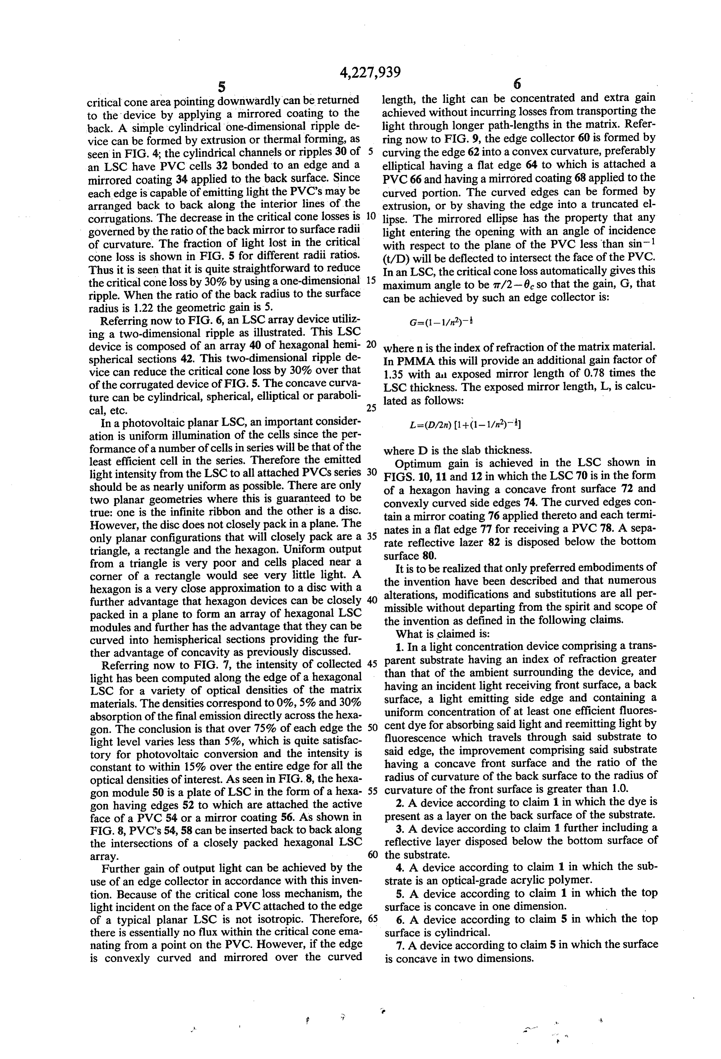
critical cone area pointing downwardly can be returned length, the light can be concentrated and extra gain to the device by applying a mirrored coating to the achieved without incurring losses from transporting the back. A simple cylindrical one-dimensional ripple de light through longer path-lengths in the matrix. Refer vice can be formed by extrusion or thermal forming, as ring now to FIG. 9, the edge collector 60 is formed by seen in FIG. 4; the cylindrical channels or ripples 30 of 5 curving the edge 62 into a convex curvature, preferably an LSC have PVC cells 32 bonded to an edge and a elliptical having a flat edge 64 to which is attached a mirrored coating 34 applied to the back surface. Since PVC 66 and having a mirrored coating 68 applied to the each edge is capable of emitting light the PVC's may be curved portion. The curved edges can be formed by arranged back to back along the interior lines of the extrusion, or by shaving the edge into a truncated el corrugations. The decrease in the critical cone losses is 10 lipse. The mirrored ellipse has the property that any governed by the ratio of the back mirror to surface radii light entering the opening with an angle of incidence of curvature. The fraction of light lost in the critical with respect to the plane of the PVC less than sin-1 cone loss is shown in FIG. 5 for different radii ratios. (t/D) will be deflected to intersect the face of the PVC. Thus it is seen that it is quite straightforward to reduce In an LSC, the critical cone loss automatically gives this the critical cone loss by 30% by using a one-dimensional maximum angle to be aw2-0 so that the gain, G, that
ripple. When the ratio of the back radius to the surface can be achieved by such an edge collector is: radius is 1.22 the geometric gain is 5.
Referring now to FIG. 6, an LSC array device utiliz ing a two-dimensional ripple as illustrated. This LSC 20 device is composed of an array 40 of hexagonal hemi where n is the index of refraction of the matrix material. spherical sections 42. This two-dimensional ripple de In PMMA this will provide an additional gain factor of vice can reduce the critical cone loss by 30% over that 1.35 with all exposed mirror length of 0.78 times the of the corrugated device of FIG. 5. The concave curva LSC thickness. The exposed mirror length, L, is calcu ture can be cylindrical, spherical, elliptical or paraboli lated as follows:
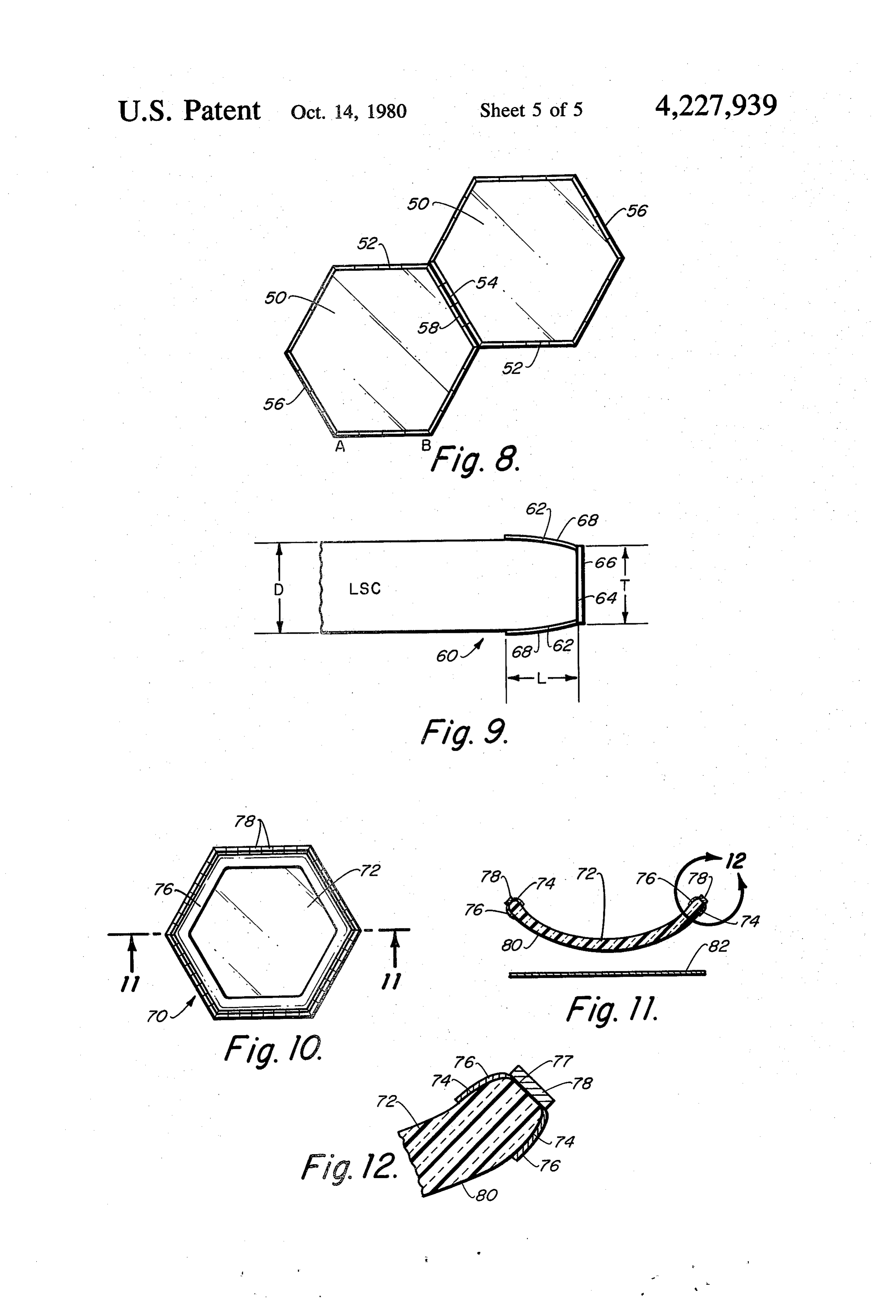
In a photovoltaic planar LSC, an important consider ation is uniform illumination of the cells since the per formance of a number of cells in series will be that of the where D is the slab thickness. least efficient cell in the series. Therefore the emitted Optimum gain is achieved in the LSC shown in light intensity from the LSC to all attached PVCs series 30 FIGS. 10, 11 and 12 in which the LSC 70 is in the form should be as nearly uniform as possible. There are only of a hexagon having a concave front surface 72 and two planar geometries where this is guaranteed to be convexly curved side edges 74. The curved edges con true: one is the infinite ribbon and the other is a disc.
However, the disc does not closely pack in a plane. The tain a mirror coating 76 applied thereto and each termi nates in a flat edge 77 for receiving a PVC 78. A sepa only planar configurations that will closely pack are a 35 rate reflective triangle, a rectangle and the hexagon. Uniform output surface 80. lazer 82 is disposed below the bottom from a triangle is very poor and cells placed near a corner of a rectangle would see very little light. A theItinvention is to be realized that only preferred embodiments of have been described and that numerous hexagon is a very close approximation to a disc with a alterations, modifications further advantage that hexagon devices can be closely missible without departingand 40 substitutions are all per from the spirit and scope of packed in a plane to form an array of hexagonal LSC the invention as defined in the following claims. modules and further has the advantage that they can be What is claimed is:
curved into hemispherical sections providing the fur 1. In a light concentration device comprising a trans ther advantage of concavity as previously discussed.
Referring now to FIG. 7, the intensity of collected 45 parent substrate having an index of refraction greater than that of the ambient surrounding the device, and light has been computed along the edge of a hexagonal having
LSC for a variety of optical densities of the matrix surface,ana incident light receiving front surface, a back materials. The densities correspond to 0%, 5% and 30% uniform concentration of atsideleast light emitting edge and containing a one efficient fluores absorption of the final emission directly across the hexa cent dye for absorbing said light and reemitting light by gon. The conclusion is that over 75% of each edge the 50 light level varies less than 5%, which is quite satisfac fluorescence which travels through said substrate to tory for photovoltaic conversion and the intensity is said edge, the improvement comprising said substrate constant to within 15% over the entire edge for all the having a concave front surface and the ratio of the optical densities of interest. As seen in FIG.8, the hexa radius of curvature of the back surface to the radius of gon module 50 is a plate of LSC in the form of a hexa 55 curvature of the front surface is greater than 1.0. gon having edges 52 to which are attached the active 2. A device according to claim 1 in which the dye is face of a PVC 54 or a mirror coating 56. As shown in present as a layer on the back surface of the substrate. FIG. 8, PVC's 54, 58 can be inserted back to back along 3. A device according to claim 1 further including a the intersections of a closely packed hexagonal LSC reflective layer disposed below the bottom surface of array. the substrate.
Further gain of output light can be achieved by the 4. A device according to claim 1 in which the sub use of an edge collector in accordance with this inven strate is an optical-grade acrylic polymer. tion. Because of the critical cone loss mechanism, the 5. A device according to claim 1 in which the top light incident on the face of a PVC attached to the edge surface is concave in one dimension. of a typical planar LSC is not isotropic. Therefore, 65 6. A device according to claim 5 in which the top there is essentially no flux within the critical cone ema surface is cylindrical.
nating from a point on the PVC. However, if the edge 7. A device according to claim 5 in which the surface is convexly curved and mirrored over the curved is concave in two dimensions.
Page 10
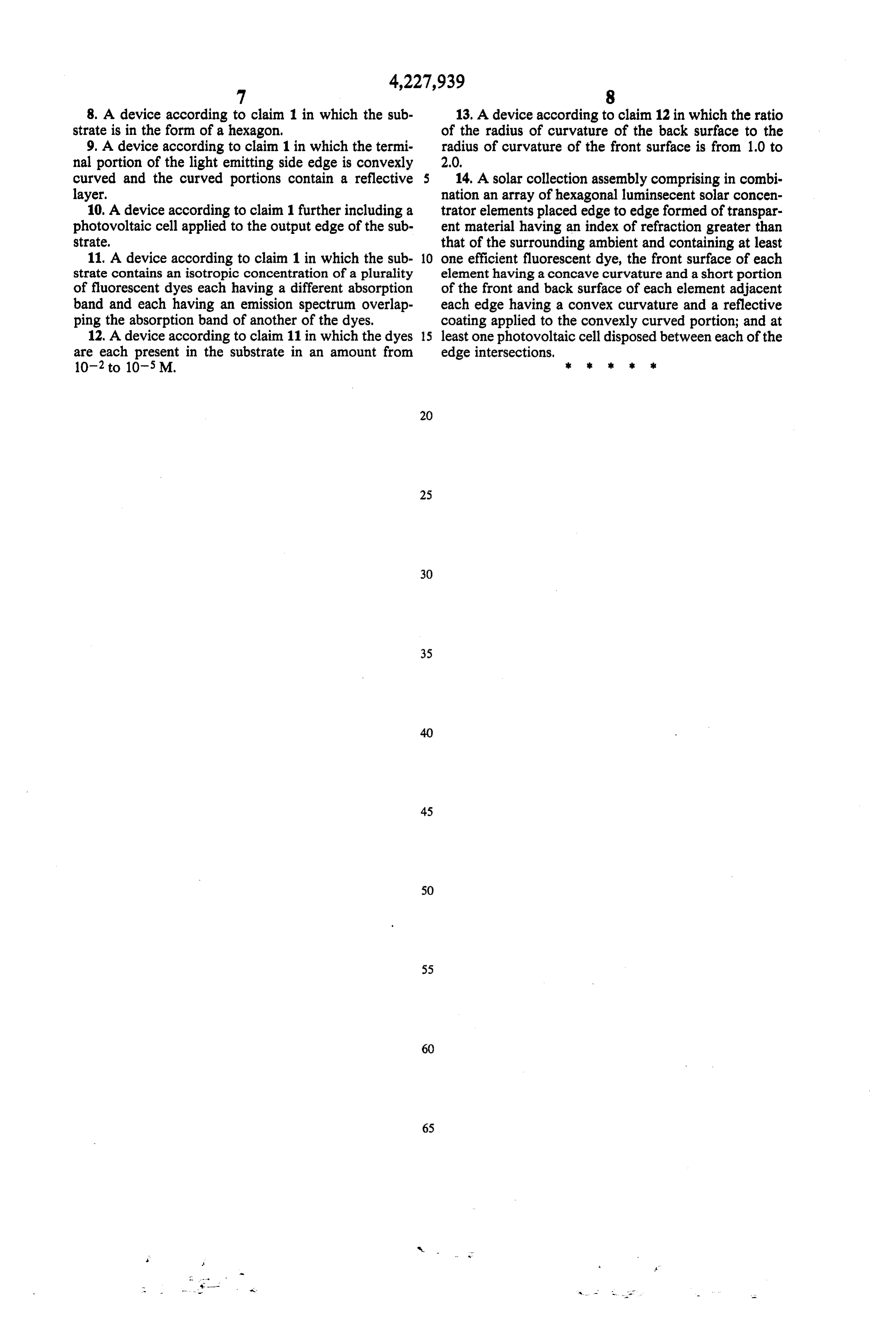
8. A device according to claim 1 in which the sub 13. A device according to claim 12 in which the ratio strate is in the form of a hexagon. of the radius of curvature of the back surface to the 9. A device according to claim 1 in which the termi radius of curvature of the front surface is from 1.0 to nal portion of the light emitting side edge is convexly 2.0, curved and the curved portions contain a reflective 14. A solar collection assembly comprising in combi layer. nation an array of hexagonal luminsecent solar concen 10. A device according to claim 1 further including a trator elements placed edge to edge formed of transpar photovoltaic cell applied to the output edge of the sub ent material having an index of refraction greater than state, that of the surrounding ambient and containing at least 11. A device according to claim 1 in which the sub 10 one efficient fluorescent dye, the front surface of each strate contains an isotropic concentration of a plurality element having a concave curvature and a short portion of fluorescent dyes each having a different absorption of the front and back surface of each element adjacent band and each having an emission spectrum overlap each edge having a convex curvature and a reflective ping the absorption band of another of the dyes. coating applied to the convexly curved portion; and at 12. A device according to claim 11 in which the dyes 15 least one photovoltaic cell disposed between each of the are each present in the substrate in an amount from edge intersections,
Provenance
- Collection
- Cited prior art
- Original PDF
- patentimages.storage.googleapis.com →
- Filed
- 1979-01-08
- Pages
- 10
- Method
- pdftotext (the PDF's own text layer) + pdftoppm 300dpi page scans
- Source
- Google Patents bibliographic record
- Granted
- 1980-10-14
- Inventors
- Ahmed H. Zewail; J. Samuel Batchelder; California Institute of Technology
- Transcribed from
- patentimages.storage.googleapis.com →