patent · US3508589
Luminous textile products
28 April 1970
Page 1
Drawing sheet — no readable text.
Page 2
Drawing sheet — no readable text.
Page 3
Drawing sheet — no readable text.
Page 4
April 28, 1970 B. N. DERICK ET All 3,508,589
LUMINOUS TEXTILE PRODUCTS
Filed Oct. 27, 1967 4. Sheets-Sheet A.
ZZZZZZZZZZZZZZZZ
ZZZZZZZZZZZZZZZZ
F G. 5 F G. | 6
H HLITE TIE TFIL ETDIL TI]L ?DTE
ATTORNEY
Page 5
United States Patent Office 3,508,589 Patented Apr. 28, 1970
"frustrated total reflection' is obtained by disrupting the 3,508,589 surface of the light transmitting portion of the optical
LUMNOUSTEXTLE PRODUCTS
Burton N. Derick and Saylor C. Snyder, Jr., Wilmington, filamentary material. In another embodiment, frustrated total reflection is obtained by bringing one or more re
Del, assignors to E. I. du Pont de Nemours and Com fraction producing solids into contact with the light trans pany, Wilmington, Del, a corporation of Delaware mitting portion. By varying the intimacy of this contact, Filed Oct. 27, 1967, Ser. No. 678,725 the illumination of the textile product varies, providing
U.S. C. 139-420 12 Claims pressure-sensitivity.
Another aspect of the present invention also involves
O integration of optical filamentary material into a textile
ABSTRACT OF THE DISCLOSURE product, but retaining the end-to-end light transmitting Upon integrating optical filamentary material into a character of the material. In this aspect, however, the textile product and frustrating the total reflection mech optical filamentary material terminates between the ex anism or "light piping' effect of the light transmitting 5 tremities of the textile product so as to be within the tex tile product, with the terminating ends of the material portion of the optical filamentary material, either before providing point source illumination, Illumination achieved or after the integration, illumination of its ends illumi in this fashion imparts a sparkle effect to the textile prod nates the textile product in the area(s) where the frustra tion is effected. By having optical filamentary material uct, particularly when it is in the form of a fabric. This manner of providing a luminous textile product can be terminate within the textile product, illumination of the 20 used in combination with the manner employing frus textile product at the ends within the product occurs. trated total reflection.
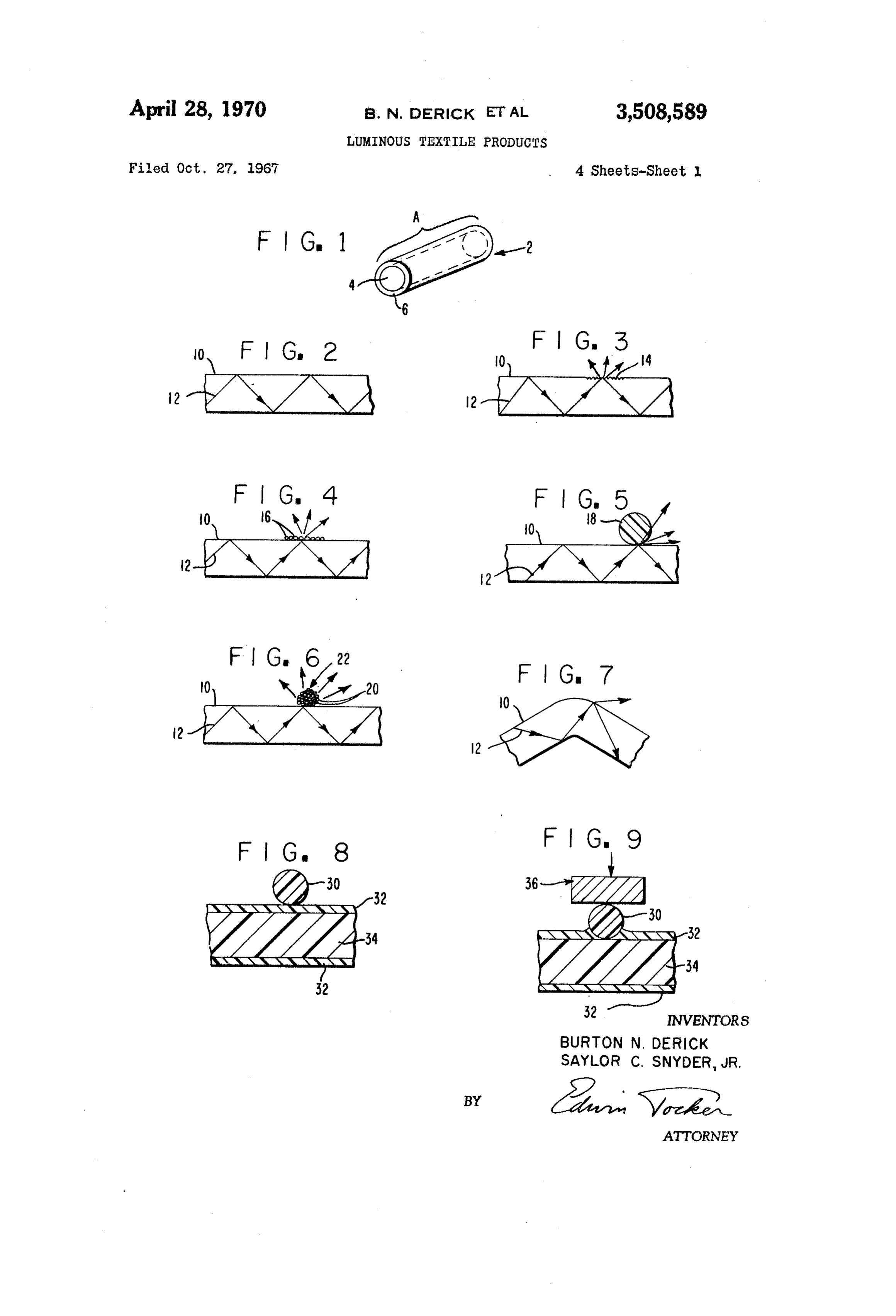
-emeranscenara These and other embodiments of the present inven This invenion relates to textile products such as fab tion will be more fully described hereinafter in connec rics, yarns and ropes, and more particularly, to products 25 tionFIG.
with the drawings, in which:
1 is a perspective view of a short length of optical which are made luminous through the incorporation of filamentary material;
optical filamentary material therein. FIG. 2 depicts in side elevation a length of an air Optical filamentary material, also called by such names sheathed optical filamentary material showing the path as light transmitting filaments or fiber optics, is becoming increasingly prominent in commerce because of its ability 30 of FIG.
a light ray therethrough;
3 depicts the unsheathed optical filamentary ma to transmit light or images along a flexible axis. Such terial of FIG. 2 showing the refractive effect of disrup material which is capable of such transmission over long tion of a portion of its surface; distances is described in British Patent 1,037,498 to Du FIGS. 4, 5 and 6 depict the unsheathed optical fila Pont. The light is transmitted along the length of the mentary material of FIG. 2 showing the refractive effect light transmitting portion of the optical filamentary ma obtained by contact with refractive producing Solids. terial by multiple internal reflections of the light therein. FIG. 7 depicts the frustration of total reflection caused Throughout the development of optical filamentary ma by excessive bending of the optical filamentary material terial great care has been taken to minimize the light of FIG. 2;
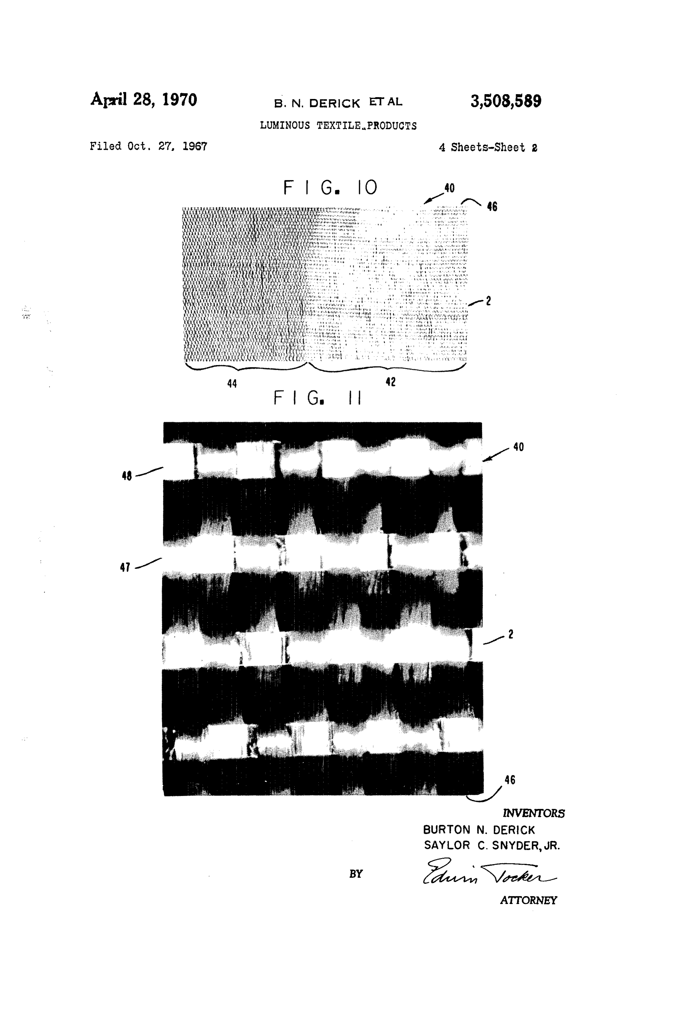
losses along the length of the optical filamentary ma FIGS. 8 and 9 depict a length of sheathed optical fila terial, or in other words to make the internal reflections 40 mentary material in longitudinal cross-section showing as total as possible, so that the light applied to one end one embodiment of steps for achieving contact between of the optical filamentary material is efficiently made the core filament and a refraction producing solid; available at the opposite end of the material. Such efforts FIG. 10 is a photograph enlarged 2X of a portion of a have included sheathing the light transmitting portion of fabric incorporating optical filamentary material and il the optical filamentary material with solid materials of 45 lustrating the luminous effect obtainable thereby; lower index of refraction which act as optical insulation, FIG. 11 is a photograph enlarged about 50X of a por minimizing the escape of light along the length of the tion of the fabric of FIG. 10;
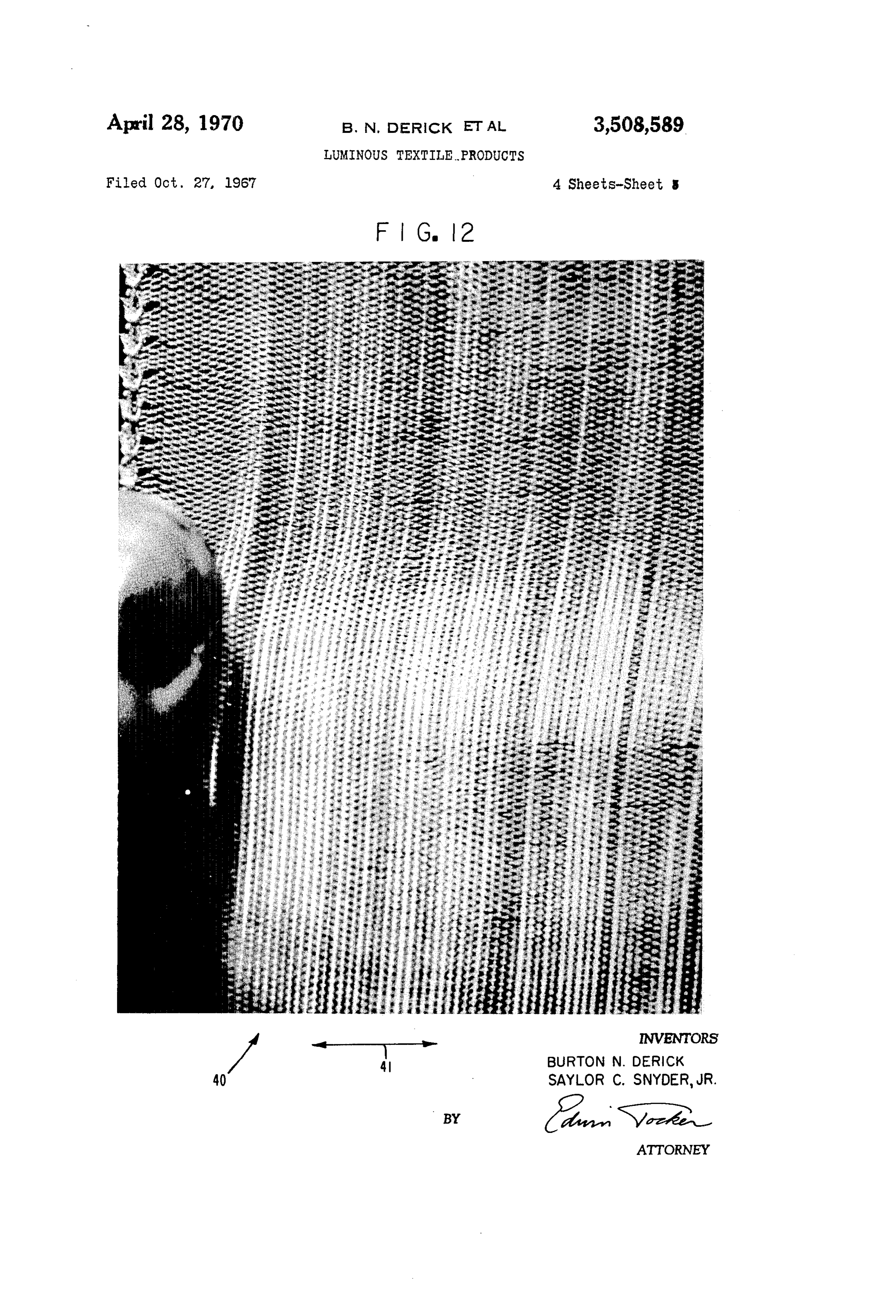
filaments. Generally, such sheathing has been of a trans FIG. 12 shows a photograph enlarged about 5X of a parent nature since opaque sheaths tend to absorb light and thereby decrease the efficiency of light transmission. 50 portion of the fabric of FIG. 10 with localized increased illumination illustrating the pressure sensitivity thereof;
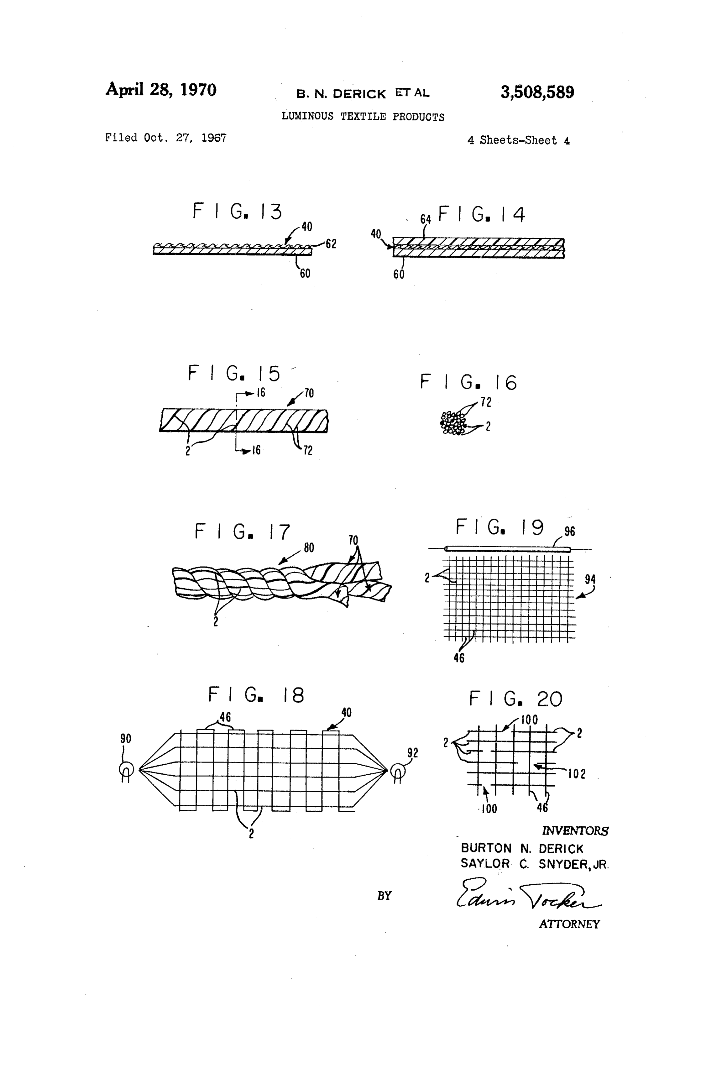
One aspect of the present invention involves the use of FIG. 13 shows schematically and in side elevation a optical filamentary material wherein the escape of trans laminate in which one layer is a fabric incorporating fea mitted light along the length of the optical filamentary material is desirable. More particularly, it has been found tures of the present invention; FIG. 14 shows schematically and in side elevation that when the optical filamentary material is incorporated, made into, or otherwise integrated into a textile product, another embodiment of laminate incorporating a fabric the textile product can be made luminous in any one or of the present invention;
more selected areas of any desired design by frustrating FIG. 15 shows a length of yarn incorporating optical the total internal reflection character of the optical fila filamentary material;
mentary material present in such areas. Illumination in FIG. 16 is a cross-section taken along line 16-16 of these selected areas is caused by light from a remote 60 FIG. 15;
source incident on the ends of the optical filamentary FIG. 17 shows a length of another textile product in material, with this light emerging from the optical fila corporating optical filamentary material; mentary material in the selected areas rather than being FIG. 18 shows schematically and in plan view a fabric transmitted end-to-end of the optical filamentary ma incorporating features of the present invention and one terial. Whereas in fiber optic technology this emergence method of causing the illumination thereof; was heretofore considered light loss and undesirable, the FIG. 19 shows a fabric incorporating features of the luminous textile products of this invention are highly de sirable. For example, the textile product can be in the present invention and another method for illumination form of a fabric providing functional or decorative il thereof; and lumination. FIG. 20 shows schematically and in plan view a por In one embodiment of this aspect of the invention, tion of a fabric containing optical filamentary material frustration of the total internal reflection character or having ends terminating within the fabric.
Page 6
DESCRIPTION OF OPTICAL FLAMENTARY transmitting portion of the optical filamentary material. MATERLAL A sheathing of opaque material, e.g., polyethylene con taining carbon black as an opacifier, can be used for clad
The present invention is applicable to optical fila ding the optically transparent sheathing hereinbefore de mentary material in general. This material consists of one scribed to better insure against unplanned light leakage. light transmitting continuous filament or a plurality of The total internal reflection character, which is a well such filaments travelling or bundled together, the mate known phenomenon, of a typical optical core-filament 10 rial being in either case flexible along its length so as to is shown in FIG. 2 by the zig-zag path of a light ray 12 be suitable for handling by textile yarn or fabric forming emanating from a remote light source (not shown), from machines and to yield a flexible textile product; generally, one side of the filament to the opposite side. Normally, this for this suitability, the material in either single filament 10 light ray would be visible as illumination at the end of or bundle form will have a maximum diameter of about the filament remote from the light source. This normal 0.080 inch. usage is employed in the one aspect of the invention where The optical filamentary material can include a solid in the filament terminates within the textile product. sheath for each filament or can be unsheathed. Generally, In accordance with another aspect of the present in however, when more than one continuous filament is vention, this total reflection character of the filament 10 present, i.e., the material is in the form of a bundle, each is modified by frustration at at least one selected location. filament is sheathed. When unsheathed, air or other fluid Then, instead of light traveling entirely end-to-end of the of lower index of refraction than the light transmitting core filament, at least a portion of the light emerges at portion of the material serves as the sheathing in the 20 each selected location. Generally, any method for ob sense that the internal reflection mechanism by which the taining this light emergence is suitable for use in the pres light transmitting portion "pipes' light from end-to-end is ent invention. However, for different applications of the retained. The unsheathed material, however, is prone to different compositions of the optical filamentary ma unplanned frustrated total reflection caused by such means terial, some methods may be better than others. Ex as disruption of its surface or contact with refraction pro exemplary of methods of frustrating total reflection are ducing solids, which would be disadvantageous to the disrupting the internal reflecting surface of the core fila planned luminous effects obtained by the present invention. ment, or bringing it into contact with at least one refrac Thus, for protective purposes, optical filamentary mate tion producing solid, or changing the geometry of the rial which incldues solid sheathing over its light transmit core filament so that the light ray no longer internally ting portion is preferred for use in the present invention, 30 reflects, or any combination of these methods. it being understood, of course, that such sheathing is re Disruption of the internal reflecting surfaces can be moved, at least where illumination by the textile product accomplished by forming a roughened area 14 in the incorporating the optical filamentary material is desired. surface of the core filament 10, as shown in FIG. 3, Such Typically, as shown in FIG. 1, the optical filamentary as by etching, grit blasting or abrading the surface. In material 2 comprises a light transmitting portion or core 35 stead of the entire light ray 12 being internally reflected, filament 4 coated with a solid sheath material 6 along a portion of it emerges as scattered light represented by its length to prevent the escape of light along its length the trio of divergent arrows in FIG. 3. (lengh A). The core filament is of clear or optical trans Refraction producing solids can be any solid which parent (low absorbance of visible light) material and 40 upon contact with the core filament causes some of can be made of either plastic or glass having such optical the light to leave the core filament instead of being character. Representative core materials include styrene totally internally reflected therein. To accomplish this, the solid has a higher index of refraction than the core polymer, including the homopolymer and copolymer with other copolymerizable monomers in minor proportion; filament. Preferably, the solid is one through which the acrylate polymer, including methyl methacrylate homo emerging light is visible. Discrete, closely spaced opaque polymer and copolymers with other copolymerizable 45 solids, however, are useful, with the emerging light being monomers in minor proportion; and barium, flint and visible as scattered reflections from one another. FIG. borosilicate crown glasses; the more dense the glass the 4 shows the scattering of light ray 12 on incidence upon better. Further details of desirable core materials are refraction producing particulate solids 16 contacting the given in British Patent No. 1,037,498. core filament 10. In FIG. 5, a portion of the light ray The sheath material should be tough, to provide pro 12 refracts through the transparent object 18 of annular tection to the core filament, and as optically transparent cross-section contacting the core-filament 10 and provides as possible. Representative sheath materials include the some scattering adjacent the object-filament interface. same materials hereinabove described as useful for core The same refractive effect, only accompanied by more materials, and in addition, the fluoroalkyl-methacrylate scattering, is obtained by the annular assemblage 22 of sheathing described in British Patent No. 1,037,498. The 5 5 FIG. 6. objects 20 of annular cross-section shown in transparent particular sheath material used will depend on the particu Exemplary of objects 16 are dust and dust-like solids lar core material used, satisfying such criteria as fabricabil and frost coatings. Exemplary of object 18 are glass and ity and ability to obtain total reflection at the sheath-core plastic beads, spheres and the like, and also mono-fila interface. The latter criteria is generally met when the mentary material. The assemblage 22 can be a yarn-like index of refraction of the sheath material is at least three 60 textile product, with the objects 20 being filaments and/or percent less than the refractive index of the core mate fibers of such translucent to transparent refraction pro rial; the greater the difference between refractive indices ducing plastic materials as polyolefins, e.g., polyethylene of the sheath and core materials the better. Representa tive combinations include methyl methacrylate polymer with polyproplene and minor and copolymers thereof with each other proportions of other ethylenically unsaturated core and fluoro-alkyl methacrylate polymer sheath; sty copolymerizable monomers; polyamides, polyesters, rene polymer core and methyl methacrylate polymer polyacrylonitriles, silk and rayons. sheath; high density glass core and low density glass sheath Changing the geometry of the core-filament, such as (such as described in U.S. Patent No. 3,148,967). Gen by bending it, as shown in FIG. 7, results in light emerg enerally, the core will have a diameter of at least 0.05 mil, and the solid sheath thickness (when sheathing is used) 70 ing mately from the surface where the angle of bend approxi exceeds the angle of internal reflection. Another will be at least three times the wavelength of light. The light, which is internally reflected by and along the core geometric change would be to form or otherwise cause filament generally penetrates the sheath to the extent of axial fluctuations to be present in the diameter of the several wavelengths of light and for this reason such thick core filament.
ness of sheathing is considered herein as part of the light The degree to which total deflection by the core fila
Page 7
ment is frustrated, by the hereinbefore described or other frustrated total reflection are employed, in which case methods, will depend on the frequency or distribution of Some or all of the other filamentary material can be of light emergence points desired. The degree of frustra non-refraction producing character. The optical fila tion at any one point along the core filament should not mentary material need not necessarily be integrated into be so great as to use up light required for transmission the textile product while the product is being made, but to other such points, otherwise such other points will 5 can be integrated therein after the product is made. For remain unilluminated. In other words, while frustration example, the optical filamentary material can be incor of total reflection at selected points is desired according porated into fabrics by sewing. to the present invention, maintainence of some total re The optical filamentary material can be modified to flection and thereby some of the end-to-end transmission O exhibit frustrated total reflection either before or after character of the core filament is also generally desired to in"egration into a textile product, depending on the insure illumination at all points of frustrated total reflec particular product and upon the particular luminous effect tion. However, this maintaining becomes less important desired. The optical filamentary material can also be inte when a light source is used to illuminate both ends of grated into a textile product in a manner in which ends the core filament, in which case the light traveling in one 5 of the optical filamentary material lie within the product direction through the filament is complemented by light So as to give a sparkle-type lumination. In one embodi traveling in the opposite direction. ment to achieve this effect, the optical filamentary ma While the methods of achieving frustrated total reflec terial is severed at selected locations within the textile tion of the core filament depicted in FIGS. 3 to 7 make product after incorporation therein. reference to an unsheathed core filament 10, such meth 20 FIG. 10 is a photograph, enlarged about 2 times, of ods and others are equally applicable to sheathed core one embodiment of textile product of this invention, filaments, it being only necessary to first remove the namely a fabric 40, illustrating one embodiment of illumi sheath at least where frustated total reflection is desired. nation effect obtainable therewith. The fabric 40 exhibits The methods of achieving the roughened area 14 (FIG. a luminous area 42 and a darkened area 44. FIG. 11 is 3) can be used for this purpose and continued on into 25 an enlargement (about 50 times) of a portion of the the core filament or replaced by other methods of achiev luminous area 42, wherein it can be seen that the fabric ing frustrated total reflection once the sheath is removed. is a 1:1 plain weave, which is the weave throughout. In the case of plastic sheath-core filaments, Solvents Single filaments of optical filamentary material 2 forms which dissolve the sheath and not the core filament can the fill direction of the weave and polyester (polyethylene be used for sheath removal. For example, acetic acid can 30 terephthalate) preferentially dissolve polymethylmethacrylate (as a yarn 46 forms the machine direction. sheath) and not polystyrene (as a core). Another meth In FIG. 11, the illumination appears as occurring from od, when the sheath is thermoplastic, is to heat the sheath ciscrete locations, namely narrow light bands 47, alter sufficiently so that it is deformable, and deform the heated nating With broader light bands 48. These light bands sheath to expose the core filament. One method of ac occur where the yarn crosses over and under the optical complishing this is to position a monofilament 30 of filamenary material to contact the light transmitting higher melting temperature than the sheath against the portion of optical filamentary material at these crossovers thermoplastic sheath 32 of core filament 34, as shown in47 aresult manner represented by FIG. 6. The narrow bands from viewing the emitted light through the in FIG. 8, and thereafter apply radiant heat and preSSure, yarn 46, With this light being scattered by the individual such as by heating iron 36 shown in FIG. 9, to force 40 fibers the monofilament through the sheath 32 and into contact of the yarn. The broader bands 48 result from with the core filament. This method can generally be viewing drical the same scattered light but through the cylin lens formed by the optical filamentary material.
applied with the objects 16, 18 and 20 discussed herein before. The same and similar methods can be employed These bands 47 and 48, when viewed in actual size pro to selectively remove any outer cladding, such as the vide a fairly uniform illumination of the entire area (see opaque sheathing hereinbefore described, that may be e.g., area 42 of FIG. 10).
present. Illumination of the fabric 40 is limited to the area 42 TEXTILE PRODUCTS by confining the frustrated total reflection character of the optical filamentary material to this area. For fabric
Textile products refers to products produced by textile 50 46, this confinement is obtained by removing the sheath operations or processes such as weaving or twisting as ing from the optical filamentary material lying in area distinguished from single filaments or bundles thereof of 42 in the manner described in Example 2 hereinafter. optical filamentary material. Thus, textile products as The optical filamentary material in the non-luminous or used herein includes yarn-like products, i.e., one or more darkened area 44 retains its sheathing and thereby its continuous strands fibers and/or filaments twisted to 55 normal end-to-end or total internal reflection character, gether, such yarn-like products including yarn, single and transmitting light from a remote light source (not shown) plied, thread, cord, braid, and rope. Textile products also to area 42.
includes fabrics, i.e., structures produced by the inter The uniformity of illumination of fabrics of this in lacing of yarns, fibers, or filaments. Textile products Vention can be varied such as by the tightness of the further includes non-woven fabrics. 60 Weave and/or by the proportion of optical filamentary The manner of integrating the optical filamentary ma material versus other material present in the fabric. The terial into a textile product will depend on the particular illumination by area 42 of fabric 40 can be made Ore product. Conventional textile equipment and processes uniform, for example, by using a tighter weave and/or by are generally applicable. Thus, the optical filamentary using Optical filamentary material in the machine di. material can be twisted with itself and/or other fila 65 rection as well.
mentary or fibrous (staple) material into yarn, and the Through the principle of confirming the frustrated total yarn can be made into other textile products, such as reflection character of the optical filamentary material thread, rope and fabrics. The optical filamentary material to any one or more selected areas, each of any design can also be made into fabrics with itself and/or other fila desired, of the fabric, variations in the overall luminous mentary or yarn-like material by conventional weaving or 70 effect are limitless. For example, the entire fabric or non-woven techniques. The other filamentary material, any selected part thereof can be made luminous. The e.g., filaments, fibers, or yarns, which come into contact illumination can be in the form of printing or other with the optical filamentary material in these textile design, such as pictures, Writing, and other forms for products can serve as refraction producing solids, al decorative or advertising purposes, or can form the back though not necessarily so if other methods of producing 75 ground for non-luminous areas in the form of printing or

Page 8
such other design. The method used for confining frus for accomplishing this is to apply pressure to one or trated total reflection to selected areas will depend on the both surfaces of the fabric in the luminous area, with particular method of achieving the frustration. For ex the increased illumination being visible in the area of ample, stenciis are useful for confining grit blasting; mask pressure application. Another method of accomplishing ing is useful for chemical etching and solvent treatment. this is by stretching the fabric with the increased illu In the hot ironing technique, the iron can be in the form mination appearing in the area of stretch. This embodi of a printing plate, with the raised portion of the plate ment is illustrated by FIG. 12, wherein fabric 40 is manu serving to frustrate the total reflection of the optical fila ally stretched in the direction of arrows 41, with the mentary material in the design of the raised portion. horizontally extending area between the fingers (only Fabrics of this invention are useful in many of the O one is shown) being brighter than the luminous area same ways as conventional fabrics, with the luminous therebelow. In another embodiment of this invention, ability thereof supplying novel decorative and utilitarian the fabric does not become visibly luminous until stretch effects. For example, the optical filamentary material may ing or pressure forces are exerted on the fabric to in be colored or have a colored sheath, or such material crease the intimacy of contact between the optical fila of several colors may be incorporated into a single fabric mentary material and the yarn. This embodiment is whereby upon illumination from a single light source, achieved, for example, by a loose weave of optical fila different color effects appear in the fabric. Similarly, mov mentary material and yarn, Such as yarn 46. ing the light source with respect to the fabric or chang This pressure-responsive effect enables fabrics of this ing the color of the light source, e.g., with a color wheel, invention to be used in pressure-sensing applications, produces novel shadow and color effects. Color, if present, 20 whether the pressure be resulting from force applied to in the transparent yarn integrated with the fiber optics a surface of the fabric or tensile forces applied in the shows up in the pastel shade. These effects are particularly plane of the fabric, with the increase, including the in useful and attractive for advertising displays. ception of, luminousness of the fabric being the indicator The fabrics of this invention, particularly those hav of the existence of such pressure. The variable illumina ing an area of substantially uniform illumination, are 25 tion feature of the fabrics of the present invention makes also useful for general illumination, such as in the manner them readily useful and attractive for advertising display of electroluminescent panels. Such fabrics, however, pro purposes.
vide the advantage that the electrical apparatus required Luminous yarn-like textile products can be made by in to activate electroluminescent panels from a D.C. Source tegrating optical filamentary materials with textile fila are not needed in the present invention. In addition, the 30 mentary material, including optical filamentary material, hard or stiff form of such panels is absent for the Soft such as by a twisting operation. For example, as shown and flexible fabrics of the present invention. in FIG. 15, a strand of yarn 70 consists of optical fila Stiff panels of fabrics of the present invention can be mentary material 2 (shown in heavy line for clarity) made, however, such as by impregnating with or encap twisted together with polyamide textile filaments 72. The sulating the fabric in a transparent or translucent plastic optical filamentary material can be present in the interior material of lower refraction (than the core filaments), of the yarn as shown in FIG. 16. The methods of achiev such as the low index thermosetting resin, e.g., epoxy ing selective frustrated reflection in fabrics, as herein resin, which subsequently harden. In such embodiment, before discussed, are generally applicable to yarn-like tex the light emitted through refraction producing Solids tile products. For example, when the other textile mate will continue to be emitted through the plastic impreg 40 rials associated with the optical filamentary material in nant. In another embodiment, the fabric 40, either by yarn 70 are refraction producing and in contact with the itself or impregnated or encapsulated as just described, light transmitting portion, light is emitted along the length can be laminated by conventional methods (such as by of the yarn, illuminating the yarn at the point(s) of light using epoxy resin adhesive) to a solid base 60 to form emission. Such yarn is useful for making into fabrics, the composite structure in FIG. 13. In still a further e.g., yarn 70 can be used in place of optical filamentary embodiment, the surface 62 facing the fabric 40 can be material 2 in fabric 40. Another application is to twist a reflective surface, so as to reflect the illumination from together a plurality of strands of yarn to form a thread the interior or facedown side of the fabric to the exterior 80, e.g., consisting of three strands of yarn 70 of FIG. 15, side thereof. as shown in FIG. 17. The resultant thread can be sewn In another embodiment, as shown in FIG. 14, a sheet into fabrics already made, and a luminous design achieved 64 of translucent material is laminated to the exterior 50 along the length of the sewn-in thread. When the other face of fabric 40 to provide a further scattering of the textile materials associated with the optical filamentary illumination from the fabric. Exemplary of translucent material (to make yarn) is of heavy denier, the re materials include opal glass and sheeting of highly crys Sultant product, resembling thread 80, will be useful as talline plastics, such as linear polyethylene and poly 55 rope. Such threads and ropes are generally useful in place propylene. of the so-called reflective threads and ropes disclosed in The fabrics of this invention are not limited to any such U.S. patents as U.S. Patent No. 3,050,824, U.S. particular form of interlaced structure, except that the Patent No. 2,382,355, and U.S. Patent No. 2,937,668. disposition of the optical filamentary material therein The principle of applying light to optical filamentary should not be such that frustrated total reflection occurs, 60 material to obtain illumination remote from the point of unplanned, by geometric disposition. This precaution also light application is applicable to illuminating textile prod applies to the integration of optical filamentary mate lucts according to the present invention. Sufficient of the rial into non-woven fabrics, which can be treated as ends of the optical filamentary material, whether the hereinbefore described to get the luminous effect desired. material is part of a fabric, yarn, thread or rope, must In fabrics such as fabric 40, wherein the optical fila 65 be exposed to the light to obtain the illumination desired. mentary material and yarn are movable relative to each In one method of accomplishing this, as shown in FIG. other at their cross-overs, the scattering effect of the 18, the fabric 40 is formed of optical filamentary mate yarn on the light emitted by the optical filamentary mate rial 2 interwoven with yarn 46, with the ends of the opti rial can be enhanced and the illumination thereby in cal filamentary material 2 extending beyond a pair of creased by increasing the intimacy of contact between O Opposite sides or edges of the fabric and converging to the yarn 46 and the optical filamentary material 2. This gether for exposure to light sources 90 and 92. The opti can be accomplished by the tightness of the weave of cal filamentary materials are sheathed or otherwise pro the fabric and/or exerting a force on the fabric which tected from light leakage until they reach the areas in forces the yarn and the optical filamentary material the fabric where luminence is desired. For long lengths against one another at their cross-overs. One method of fabric, the use of light Sources, e.g., 90 and 92, at each
Page 9
end is desirable. Instead of exposing both ends of each replaced by the same optical filamentary material forming filament 2 to light sources 90 and 92, light source 90 can the other direction of the weave. Upon sandblasting and be applied to every other filament 2, with light source 92 illumination, similar illumination results are obtained. being applied to the remaining filaments 2. For short (f) Paragraph 1(c) is repeated except that the optical lengths of fabric, a single light source is generally suffi 5 filamentary material is part of a polyester yarn (1:3). cient. An example of such an arrangement is shown in Upon Sandblasting and illumination similar results are FIG. 19, wherein a fabric 94 consists of optical filamen obtained. The yarn by itself is luminous and when twisted tary material 2 interwoven with yarn 46 with the filaments together with other like strands of yarn, the resultant 2 terminating at an edge of the fabric which runs along thread is luminous.
the length of a neon lamp 96 to receive the illumination O EXAMPLE 2 therefrom and transmit it to the illumination area of the fabric. These methods of lighting and others are appli A 3 inch wide by 24 inches long strip of fabric prepared cable to other textile products of the present invention, as in Example 1 (a) above is placed in "Freon' F-113 such as yarns, threads and ropes. (CCl2FCClF2) solvent, at room temperature and agitated A luminous effect which is different than that resulting 15 with ultrasonic agitation. The fabric is removed from the from frustrated total reflection is obtained when the opti bath after three hours and allowed to dry. When this strip cal filamentary material terminates within the textile prod is tested by illuminating from each end, the fabric glows, uct since the illumination is concentrated at the ends of resulting from the refraction producing effect of and light the material, providing point-source or "sparkle' illumina Scattering by the yarn at the crossovers, whereat sheath tion. FIG. 20 shows a fabric incorporating this embodi 20 ing has been removed, with the optical filamentary mate rial.
ment of illumination, with the fabric being a 1:1 plain EXAMPLE 3 weave of optical filamentary material 2 and textile yarn 46. The material 2, however, instead of passing continu A sample of the fabric prepared as in Example 1 (a) ously through the fabric, terminates within the fabric, leaving spaced ends 100 and 102 of optical filamentary 25 above is wiped along a portion of its length with a cloth material, the ends 100 representing those on the left hand saturated with "Freon” F-113 solvent. When this strip side of the space between the ends and the ends 102 rep of fabric is illuminated from both ends of the bundle, it resenting the opposite side. glows but not as uniformly as in Example 2, thus indi When light from a remote source (not shown) is ap cating that the fluoropolymer sheath has not been removed plied such as shown in FIG. 19, but with the light travel 30 as uniformly as in Example 2.
ing from left right, only the ends 100 are luminous. For EXAMPLE 4 the reverse direction of light travel, only ends 102 are luminous. For dual direction of light travel, such as ob A Strip of fabric is prepared as in Example 1 (a). It is tained in FIG. 18, the ends 100 and 102 both glow. If then ironed along a portion of its length with a conven the optical filamentary material 2 were modified to have tional electrically heated iron at a temperature suitable for frustrated total reflection preceding its glowing end 100 ironing polyester fiber. This treatment presses the polyester or 102, a combination of area illumination and point yarn through the sheath of fluorocarbon resin and pro source illumination results. These principles also apply for duces contact with the core of the optical filamentary other textile products such as hereinbefore described. material. When this strip is illuminated with a bright light Several examples of textile products of the present in 40 from both ends, the strip glows uniformly along the hot vention are described as follows: ironed portion.
EXAMPLE 5
EXAMPLE 1.
(a) A 1: 1 plain woven fabric is woven using the opti A sample of fabric is woven from polyester yarn and cal filamentary material (sheath-core filament) described unsheathed optical filamentary material of Example 1 (a). in Examples III (components) and V (dimensions) of When this sample of fabric is illuminated from both ends, British Patent No. 1,037,498 and polyethylene tereph it glows uniformly similar to Example 2. thalate yarn having a denier of 80 and having a count of EXAMPLE 6 33 threads/strand. This fabric is cut into 3 inch wide strips parallel to the optical filamentary material and 24 inches Example 1 (c) is repeated using the sheath-core filament long. The optical filamentary material only at each end (polystyrene core and polymethylmethacrylate sheath) de of the fabric is gathered into a bundle and cemented into scribed in Example II of British Patent No. 1,037,498 as an epoxy cement and surrounded with a metal ferrule. the optical filamentary material. Soaking of a portion of One such strip of fabric is illuminated with a bright light the fabric in acetic acid dissolves the sheath. Illumination source, and the fabric does not glow. 5 5 results similar to Example 2 are obtained. When another (b) A second strip of the fabric is lightly sandblasted strip of the same fabric is hot ironed, illumination results along about 16 inches of its length and then illuminated similar to Example 4 are obtained. from both ends as above. About 2 inches of the fabric closest to the ferrules glow, thus indicating that all of the EXAMPLE 7 light is being dissipated in the glowing first 2 inches. 60 A 1:1 plain woven fabric is made by weaving 0.003 (c) A third strip is given a much less severe sandblast inch diameter glass filament with polyethylene yarn. ing treatment along about the same length as in paragraph Illumination of the ends of the glass filaments produces a (b), and when illuminated from the ends, the entire sand uniformly luminous fabric.
blasted length of the fabric glows. This test indicates that As many apparently widely different embodiments of light sandblasting can be employed as a way of remov this invention may be made without departing from the ing the sheath to produce a fabric that will glow. This spirit and scope thereof, it is to be understood that this experiment is repeated using a stencil of the letter A, and invention is not limited to the specific embodiments thereof upon sandblasting and illumination, this letter appears except as defined in the appended claims. as the illuminated area of the fabric.
(d) A fourth strip is abraded lightly along 16 inches of 70 What is claimed is:
its length using 600 grit paper and when illuminated from 1. A textile product containing as an integral part both ends, the entire 16 in. length of the fabric glows. thereof optical filamentary material, with at least a se Similar results are obtained when crocus cloth is used in lected portion of said optical filamentary material being place of 600 grit paper. characterized by frustrated total reflection so as to render (e) Paragraph 1(c) is repeated except that the yarn is said product luminous thereat upon exposure of said opti
Page 10
cal filamentary material to a source of light at a point rial to light, whereby illumination of said textile product remote to said selected portion. in the area of said selected portion occurs. 2. The textile product of claim 1 in combination with References Cited said source of light.
3. The textile product of claim 1 in the form of a fabric. 5 UNITED STATES PATENTS 4. The textile product of claim 1 in the form of a yarn. 2,372,868 4/1945 Warren -------------- 57-146 5. The textile product of claim 1 in the form of a thread. 2,382,355 8/1945 Warren ----------- 57-140 X 6. The textile product of claim 1 in the form of a rope. 2,687,673 8/1954 Boone.
7. The textile product of claim 1 containing yarn inter laced with said optical filamentary material to produce a O 3,247,756 4/1966 Siegmund.
fabric. FOREIGN PATENTS 8. The textile product of claim 7 wherein said yarn is a 1,037,498 7/1966 Great Britain. refraction producing material and is in contact with the OTHER REFERENCES light transmitting portion of said optical filamentary mate rial. 5 A.C.M.I. (American Cystoscope Makers, Inc.), May 9. The textile product of claim 7 wherein said optical 1960.
filamentary material is in the form of single filaments. Industrial Electronics, vol. 4, No. 10, October 1966, pp. 10. The textile fabric of claim 1 wherein said optical 470-471.
filamentary material is composed of light transmitting core Mechanix Illustrated, vol. 62, No. 461, October 1966, and a sheath, except at least in said selected portion. 20 pp. 92,93, 152.
11. The textile fabric of claim 10 wherein said core is Nature, vol. 173, No. 4392, January 1954, pp.39-41. plastic.
12. A process for illuminating a textile product compris JAMES KEE CHI, Primary Examiner ing integrating optical filamentary material into said textile product, frustrating the total reflection of at least 25 U.S. C. X.R. a selected portion of said optical filamentary material, and 57-140; 65-1; 88-1; 161-175; 350-96 exposing a remote portion of said optical filamentary mate
Provenance
- Collection
- Cited prior art
- Original PDF
- patentimages.storage.googleapis.com →
- Filed
- 1967-10-27
- Pages
- 10
- Method
- pdftotext (the PDF's own text layer) + pdftoppm 300dpi page scans
- Source
- Google Patents bibliographic record
- Granted
- 1970-04-28
- Inventors
- Burton N Derick; Saylor C Snyder Jr; EI Du Pont de Nemours and Co
- Transcribed from
- patentimages.storage.googleapis.com →