patent · US4110123
Apparatus for converting light energy into electrical energy
29 August 1978
Page 1 — bibliographic record
United States Patent (19) (11) 4,110,123 Goetzberger et al. m 45 Aug. 29, 1978 54 APPARATUS FOR CONVERTING LIGHT (56) References Cited ENERGY ENTO ELECTRICAL ENERGY U.S. PATENT DOCUMENTS 3,020,411 2/1962 Cheroff................................ 250/208 75 Inventors: Adolf Goetzberger, Merzhausen; 3,426,212 2/1969 Klaas..... ... 250/226 Waldemar Greubel, Denzlingen, both 3,591,420 7/1971 Streed .................................... 136/89 of Fed. Rep. of Germany 3,751,303 8/1973 Kittl ....................................... 136/89 3,880,663 4/1975 Shaw et al. ... . . 106/47 Q 3,912,931 10/1975 Gravisse et al... ... 250/458 73) Assignee: Fraunhofer-Gesellschaft zur 3,929,510 12/1975 Kittl ..................................... 136/206 Forderung der angewandten 4,021,267 5/1977 Dettling ........................... 136/89 PC Forschung e.V., Munich, Fed. Rep. of
Germany FOREIGN PATENT DOCUMENTS
21 Appl. No.: 793,816 Primary Examiner-Aaron Weisstuch Attorney, Agent, or Firm-John C. Smith, Jr.
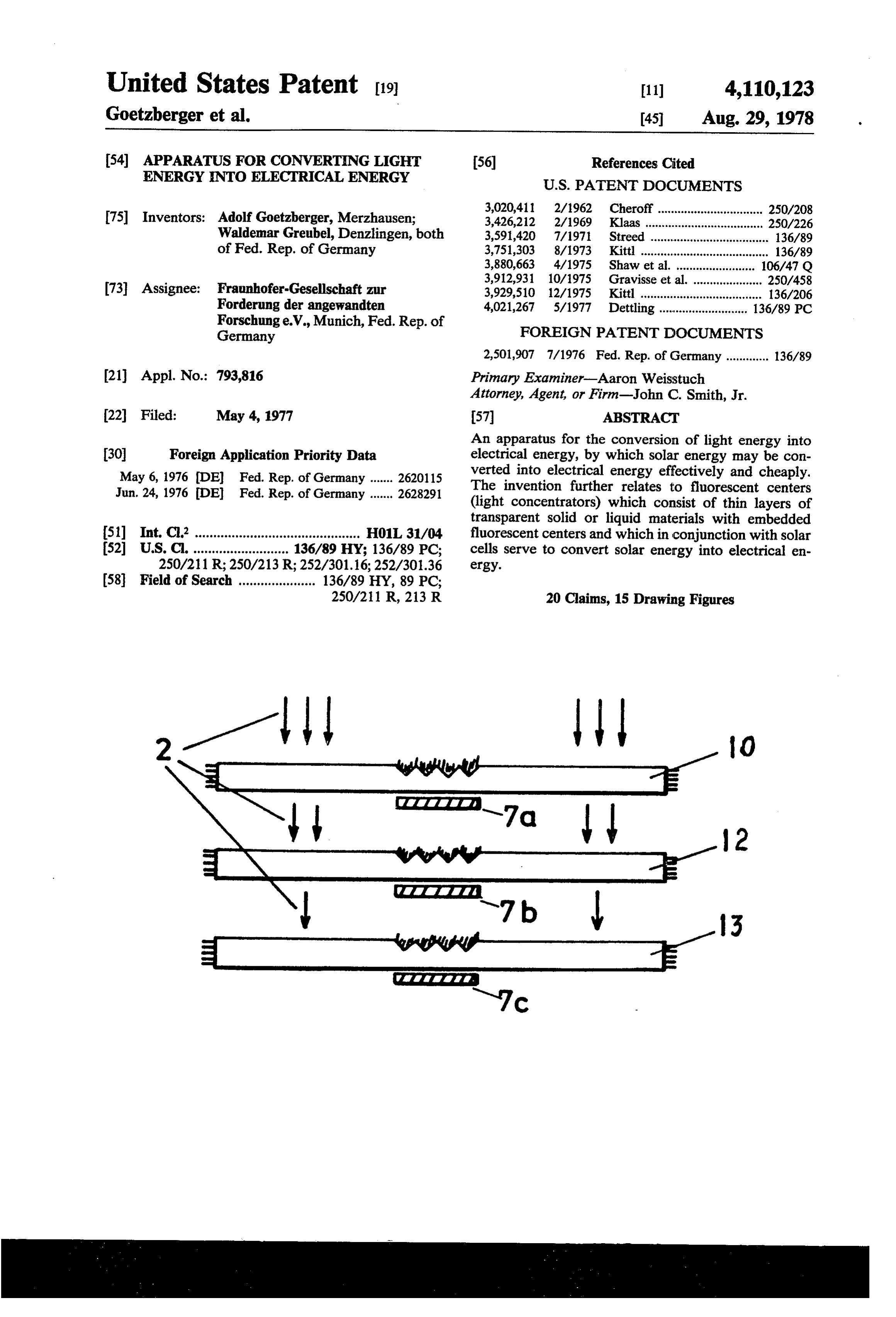
22 Filed: May 4, 1977 57 ABSTRACT An apparatus for the conversion of light energy into (30) Foreign Application Priority Data electrical energy, by which solar energy may be con May 6, 1976 (DE Fed. Rep. of Germany ....... 262O115 verted into electrical energy effectively and cheaply. Jun. 24, 1976 (DE) Fed. Rep. of Germany ....... 2628291 The invention further relates to fluorescent centers (light concentrators) which consist of thin layers of transparent solid or liquid materials with embedded 51) Int. C.’............................................. H01 L, 31/04 fluorescent centers and which in conjunction with solar 52 U.S. C. .......................... 136/89 HY; 136/89 PC; cells serve to convert solar energy into electrical en 250/211R; 250/213 R; 252/301.16; 252/301.36 ergy.
250/211 R, 213 R 20 Claims, 15 Drawing Figures
irrrrrl- 3
Page 2
Drawing sheet — no readable text.
Page 3
Drawing sheet — no readable text.
Page 4
Drawing sheet — no readable text.
Page 5
Drawing sheet — no readable text.
Page 6
Drawing sheet — no readable text.
Page 7
Drawing sheet — no readable text.
Page 8
APPARATUS FOR CONVERTING LIGHT ENERGY DESCRIPTION OF THE PREFERRED INTO ELECTRICAL ENERGY EMBODEMENTS
BACKGROUND OF THE INVENTION In the apparatus proposed here, the mentioned disad 5 vantages are to be materially reduced. In doing so, the
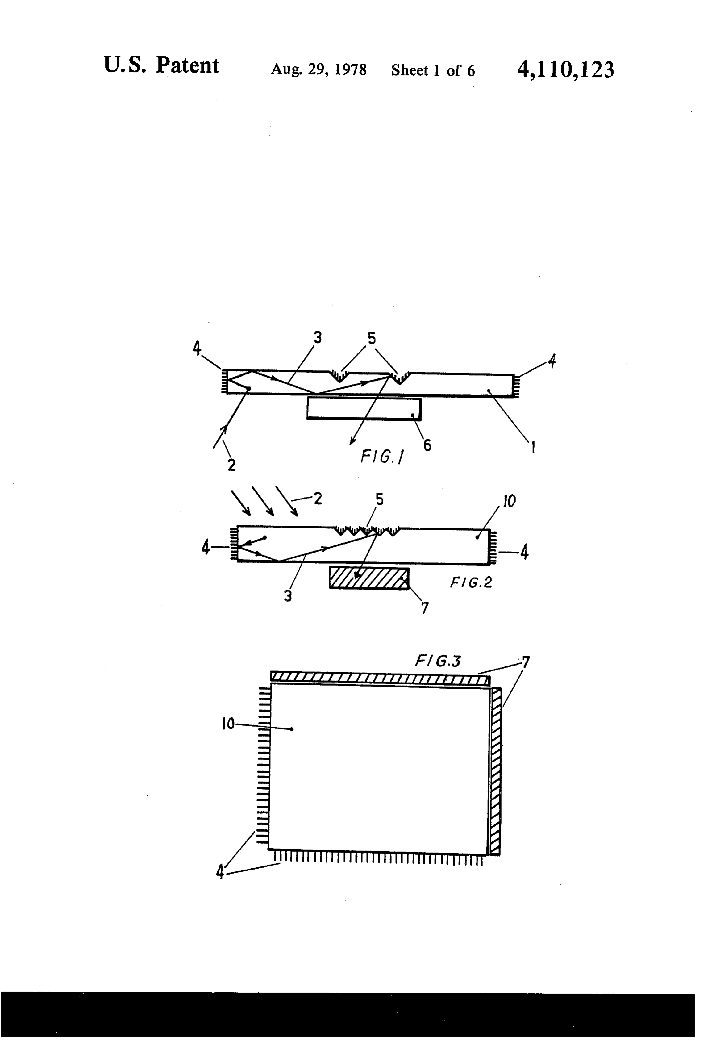
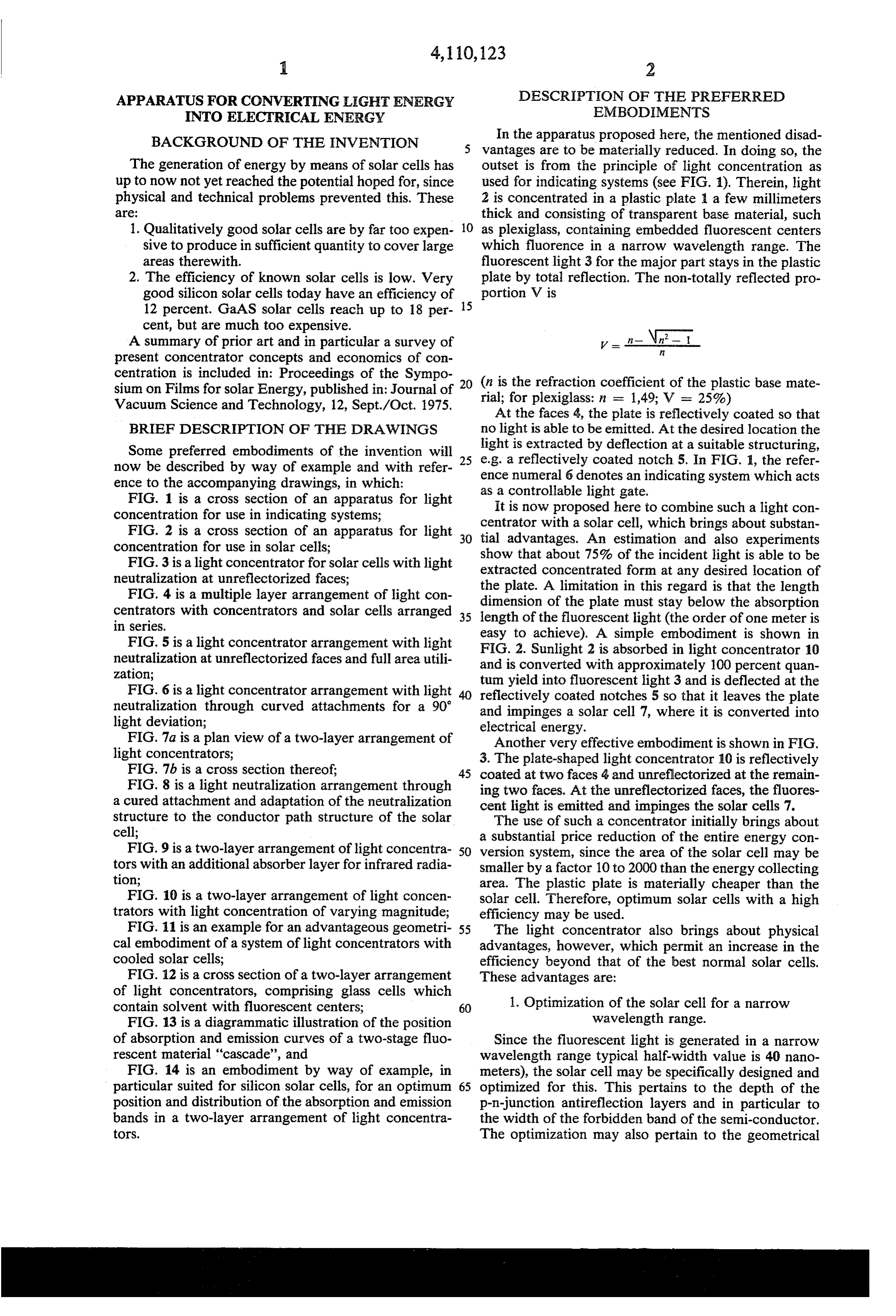
The generation of energy by means of solar cells has outset is from the principle of light concentration as up to now not yet reached the potential hoped for, since used for indicating systems (see FIG. 1). Therein, light physical and technical problems prevented this. These 2 is concentrated in a plastic plate 1 a few millimeters are: thick and consisting of transparent base material, such 1. Qualitatively good solar cells are by far too expen 10 as plexiglass, containing embedded fluorescent centers sive to produce in sufficient quantity to cover large which fluorence in a narrow wavelength range. The areas therewith. fluorescent light 3 for the major part stays in the plastic 2. The efficiency of known solar celis is low. Very plate by total reflection. The non-totally reflected pro good silicon solar cells today have an efficiency of portion V is 12 percent. GaAS solar cells reach up to 18 per 15 cent, but are much too expensive.
A summary of prior art and in particular a survey of present concentrator concepts and economics of con centration is included in: Proceedings of the Sympo 20 sium on Films for solar Energy, published in: Journal of (n is theplexiglass:
refraction coefficient of the plastic base mate
Vacuum Science and Technology, 12, Sept./Oct. 1975. rial;Atfor n = 1,49; V = 25%) the faces 4, the plate is reflectively coated so that
BRIEF DESCRIPTION OF THE DRAWINGS no light is able to be emitted. At the desired location the Some preferred embodiments of the invention will e.g. light is extracted by deflection at a suitable structuring, now be described by way of example and with refer 25 ence a reflectively coated notch 5. In FIG. , the refer ence to the accompanying drawings, in which: numeral 6 denotes an indicating system which acts FIG. 1 is a cross section of an apparatus for light as a controllable light gate.
concentration for use in indicating systems; It is now proposed here to combine such a light con FIG. 2 is a cross section of an apparatus for light 30 tial centrator with a solar cell, which brings about substan concentration for use in solar cells; advantages. An estimation and also experiments show
FIG. 3 is a light concentrator for solar cells with light extracted that about 75% of the incident light is able to be neutralization at unreflectorized faces; concentrated form at any desired location of FIG. 4 is a multiple layer arrangement of light con the plate. A limitation in this regard is that the length centrators with concentrators and solar cells arranged 35 dimension length of of the plate must stay below the absorption the fluorescent light (the order of one meter is in series.
FIG. 5 is a light concentrator arrangement with light easy to achieve). A simple embodiment is shown in FIG. 2. Sunlight 2 is absorbed in light concentrator 10 neutralization at unreflectorized faces and full area utili and is converted with approximately 100 percent quan zation; tum yield into fluorescent light 3 and is deflected at the FIG. 6 is a light concentrator arrangement with light reflectively coated notches 5 so that it leaves the plate neutralization through curved attachments for a 90 and impinges a solar cell 7, where it is converted into light deviation; electrical energy.
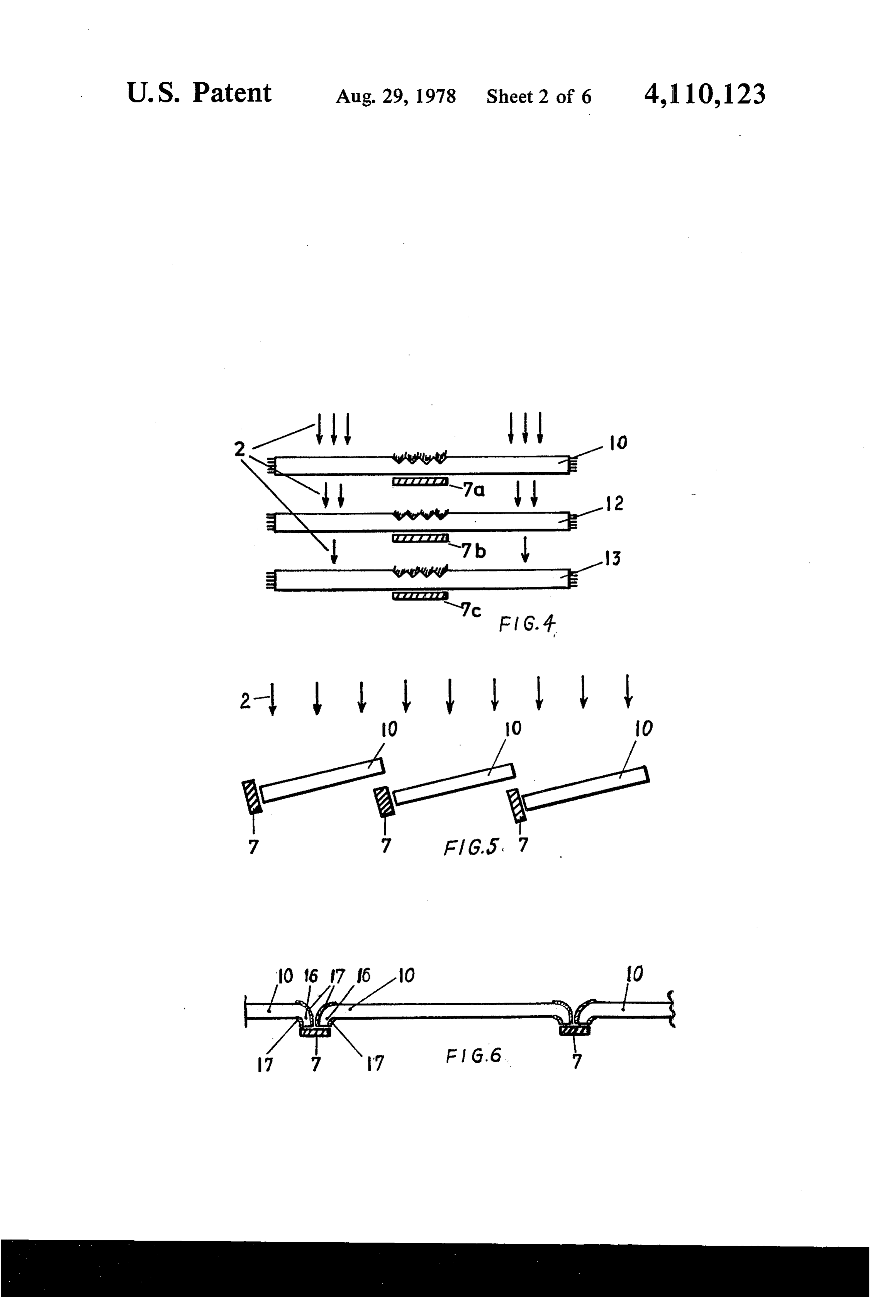
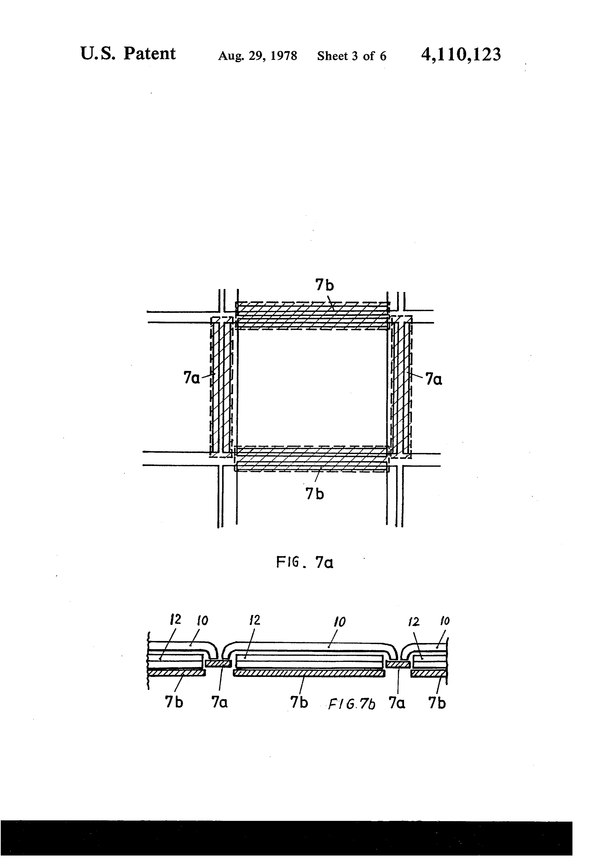
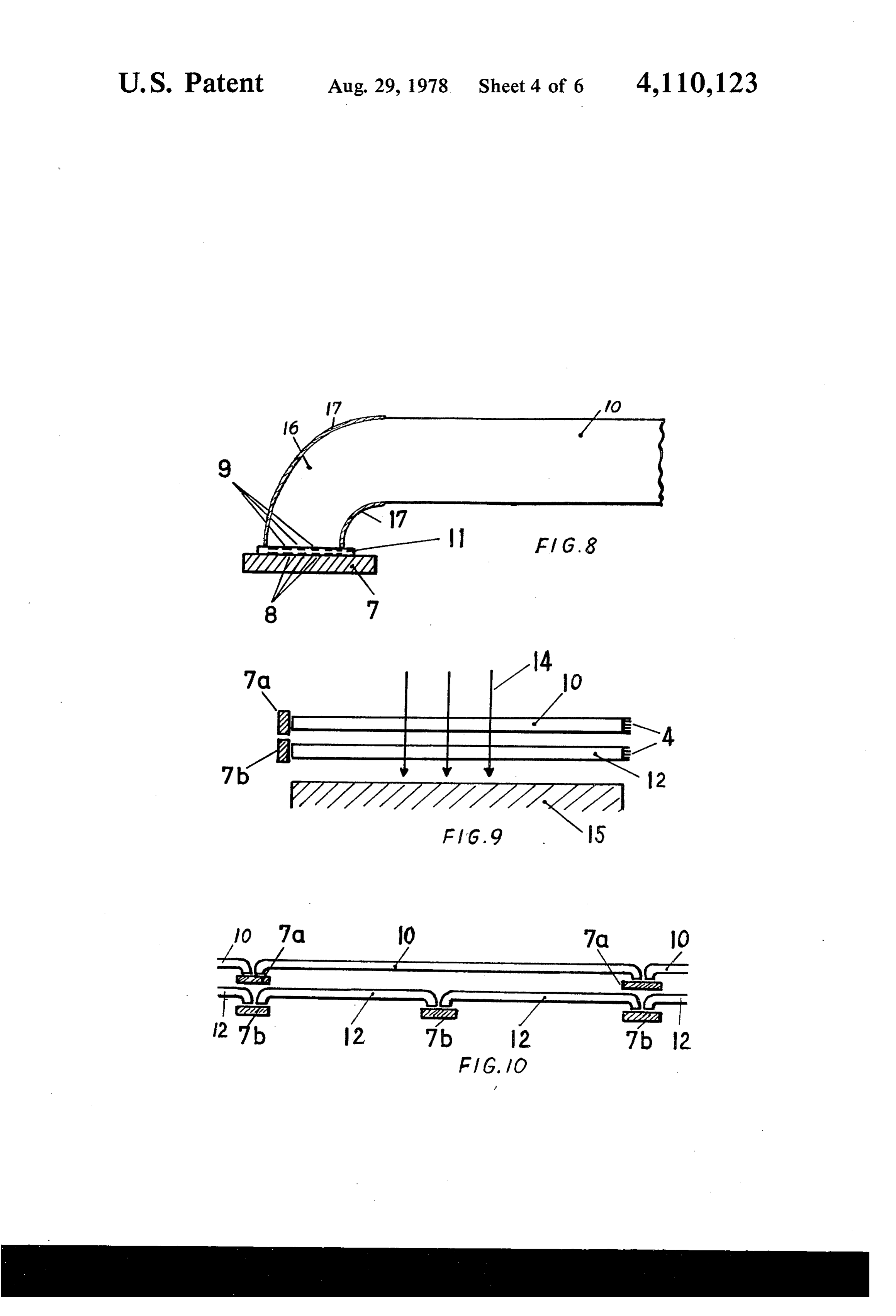
FIG. 7a is a plan view of a two-layer arrangement of Another very effective embodiment is shown in FIG. light concentrators; 3. The plate-shaped light concentrator 10 is reflectively FIG. 7b is a cross section thereof; 45 coated at two faces 4 and unreflectorized at the remain FIG. 8 is a light neutralization arrangement through ing two faces. At the unreflectorized faces, the fluores a cured attachment and adaptation of the neutralization cent light is emitted and impinges the solar cells 7. structure to the conductor path structure of the solar The use of such a concentrator initially brings about cell; a substantial price reduction of the entire energy con FIG. 9 is a two-layer arrangement of light concentra 50 version system, since the area of the solar cell may be tors with an additional absorber layer for infrared radia smaller by a factor 10 to 2000 than the energy collecting tion; area. The plastic plate is materially cheaper than the FIG. 10 is a two-layer arrangement of light concen solar cell. Therefore, optimum solar cells with a high trators with light concentration of varying magnitude; efficiency may be used.
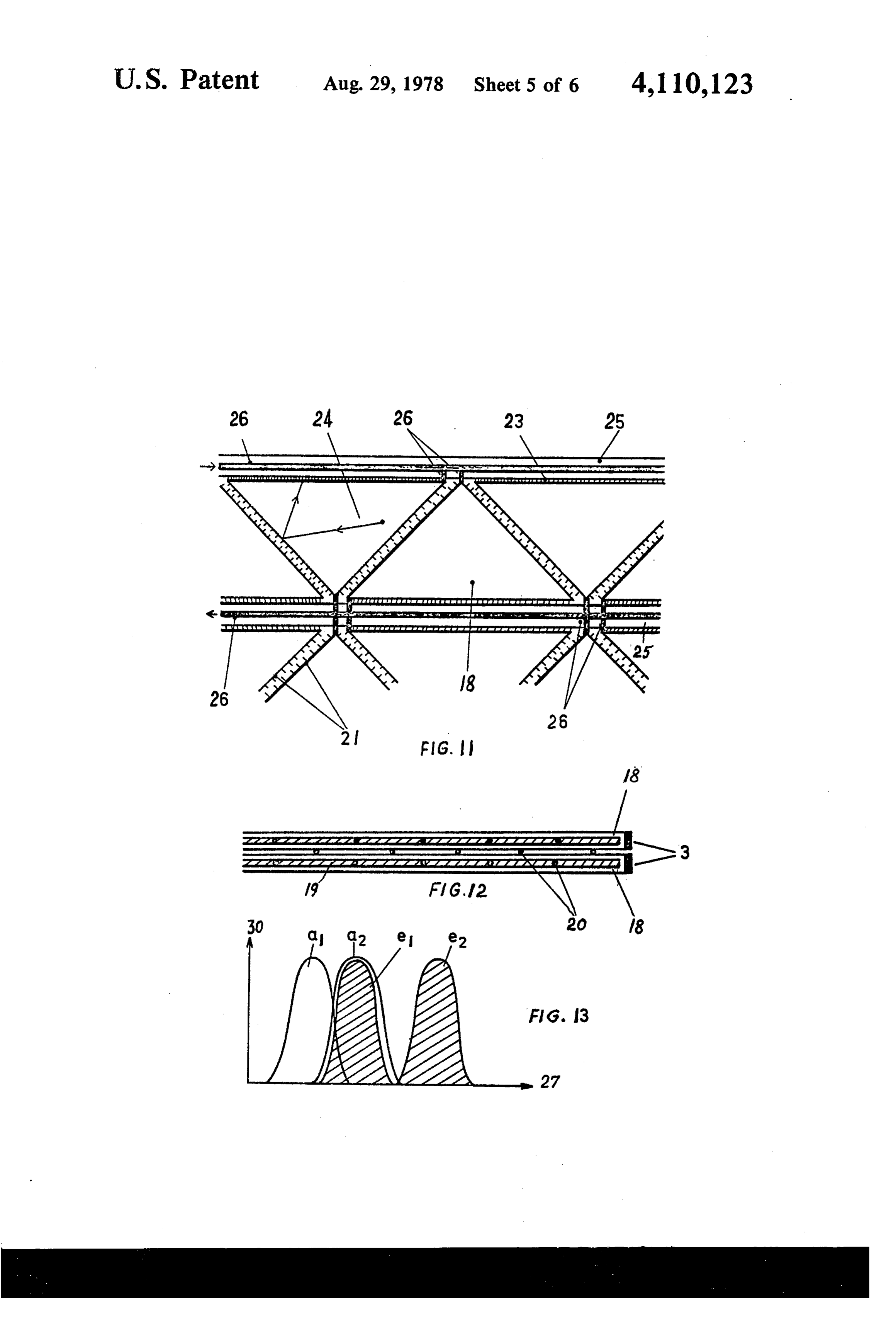
FIG. 11 is an example for an advantageous geometri 55 The light concentrator also brings about physical cal embodiment of a system of light concentrators with advantages, however, which permit an increase in the cooled solar cells; efficiency beyond that of the best normal solar cells. FIG. 12 is a cross section of a two-layer arrangement These advantages are:
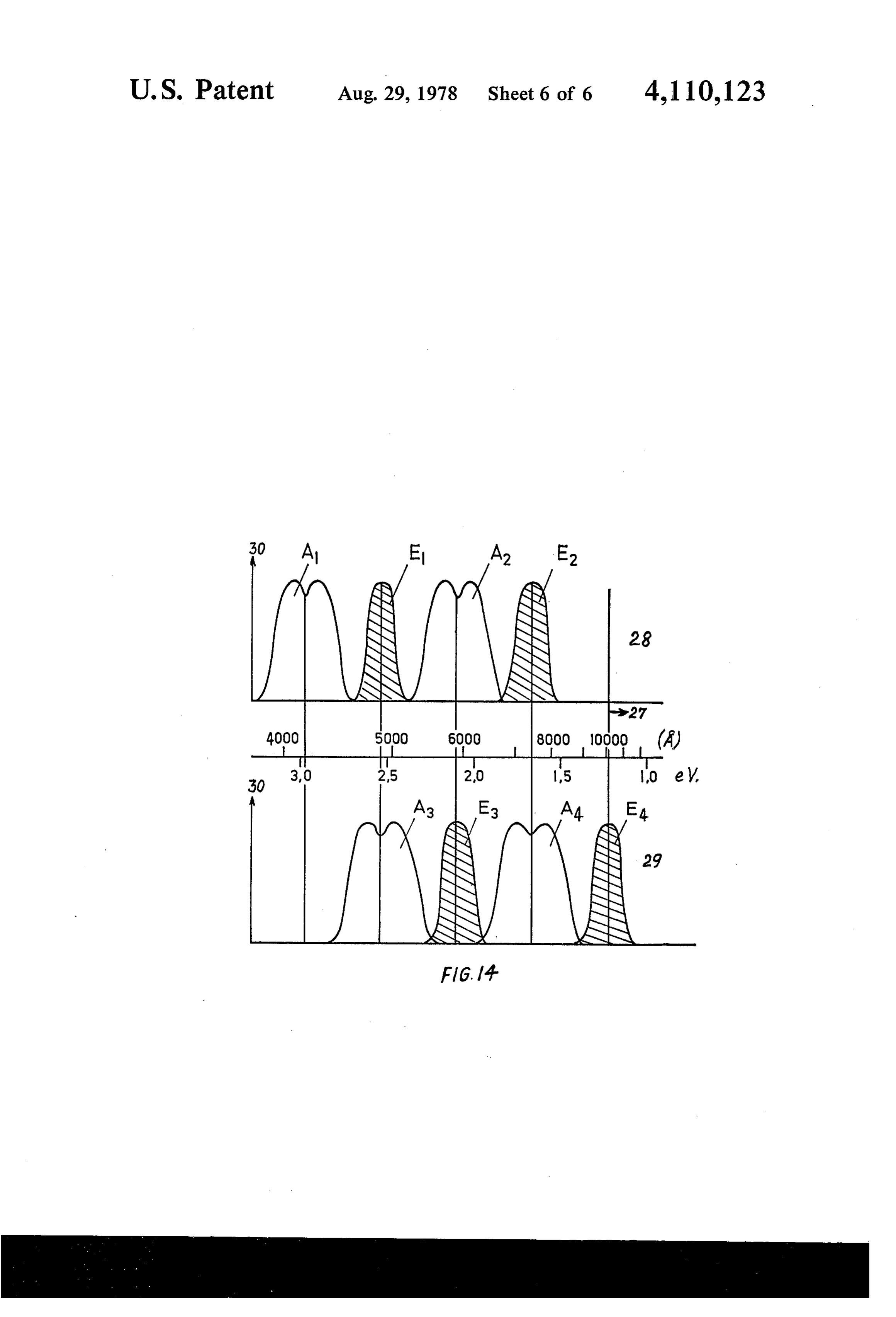
of light concentrators, comprising glass cells which contain solvent with fluorescent centers; 60 1. Optimization of the solar cell for a narrow FIG. 13 is a diagrammatic illustration of the position wavelength range. of absorption and emission curves of a two-stage fluo Since the fluorescent light is generated in a narrow rescent material 'cascade', and wavelength range typical half-width value is 40 nano FIG. 14 is an embodiment by way of example, in meters), the solar cell may be specifically designed and particular suited for silicon solar cells, for an optimum 65 optimized for this. This pertains to the depth of the position and distribution of the absorption and emission p-n-junction antireflection layers and in particular to bands in a two-layer arrangement of light concentra the width of the forbidden band of the semi-conductor. tors. The optimization may also pertain to the geometrical
Page 9
deisgn of the structure of the solar cell. Solar cells must course only represents an embodiment by way of exam have contact grids on their surfaces, since the thin sur ple. More than three layers, but also only two layers face layers of the semiconductor do not have sufficient may be used. By using concentrators repeatedly ar conductivity. The semiconductor areas under these ranged in series with adapted solar cells, a material metallized surfaces are lost for light collection. Accord increase of efficiency is able to be obtained which sub ing to FIG. 8, the contact grids may be excluded from stantially outrates the losses of the concentrators. Thus, radiation and thus be dimensioned to an optimum. To the overall system has an efficiency which is higher accomplish this, a reflector structure 9 is applied to the than is possible to achieve with the best known solar flourescent light emission surface of the light concentra 10 cells.
tor which precisely corresponds to the contact grid The series arrangement is possible only with the con structure 8 of the solar cell 7. The fluorescent light centrator system, since solar cells themselves cannot be emission surface and the solar cell are then brought into rendered radiation-permeable without substantial im optical contact with one another through a suitable film pairment. Solar cells contain electrical contacts as well 11 in such a way that the structures 8 and 9 overlap. 15 as highly doped zones both of which have a high ab 2. Effectiveness of the apparatus for diffuse daylight. sorption. Since the base material of the concentrators is transparent, lower reflection losses also occur than for
The concentrator is also fully sensitive to diffuse semi-conductors. In the series arrangement reflection light. Arrangements are, for instance, known where losses do occur at the interfaces, however, these are sunlight is concentrated by means of reflectors on solar 20 low, because of the high degree of transparency. On the cells of high efficiency. These have the disadvantage other hand, an increase in efficiency results, because that the reflectors must be permanently oriented toward fluorescent light emitted downwardly outside of the the sun so that this arrangement works only with clear angle of total reflection is received by the next plate and sky conditions. It is likewise known that for diffuse light is utilized there again by the embedded fluorescent incidence and slightly covered sky conditions the the 25 centers. Losses are thus approximately halved. incident radiation energy is only very slightly reduced, The good transparency of the concentrators also but rather is undirected. The apparatus according to the permits utilization of heat radiation not convertible by invention has the advantage that it remains fully effec solar cells.
tive for diffuse light and also requires no complex foll FIG. 9 shows how IR radiation 14 passes through low-up devices. 30 concentrators 10 and 12 and strikes IR radiation ab 3. Effective utilization of the energy of sunlight. sorber 15 which converts this residual radiation into heat.
Conventional solar cells have the disadvantage that the full energy of incident light quanta cannot be uti 4. Specific embodiments. lized, since for all photons with a higher energy than Geometries of the concentrators may be of different that of the forbidden band of the semi-conductor mate 35 nature, and in particular the neutralization of light may rial this excess energy is not converted into electrical be optimized. The embodiment shown in FIGS. 1, 2 and energy, but is lost as heat. Silicon, e.g., has a band width 4 with the solar cells in the middle of the concentrators of 1.1 eV. The maximum photon energy of sunlight, however, is 2.58 eV. Thus, for each photon independent isranged only one possibility. The solar cells may also be ar of its original energy, only about 1 eV. is converted, and area mayatbe the edge of the concentrators, and thereby the fully utilized, as illustrated in FIG. 5. There this quantitatively means that in a silicon ell about 40% the solar cells 7 are attached to unreflectorized of the of the incident photon energy is not utilized. There are light concentrators 10.
proposals how the efficiency could be increased by A further possibility of light neutralization is repre using a solar cell with a variable band gap or by hetero 45 sented junction or by lamination of solar cells with varying trators by 10
FIG. 6. In this modification, the light concen have curved attachments 16 at opposite edges band gaps. All these proposals have gained no signifi for a 90 deflection cance up to now, since they are either difficult to realize attachments 16 are of light. The surfaces of the curved provided with a reflecting coating technically or are too high in cost.
By means of the concentrators according to this in 50 7 denote the solar cells again. ItThe 17 in order to avoid light losses. reference numerals should be appreciated vention, a better utilization of the various energy ranges that in the arrangements shown antireflection layers on of sunlight may be achieved in a very simple way.
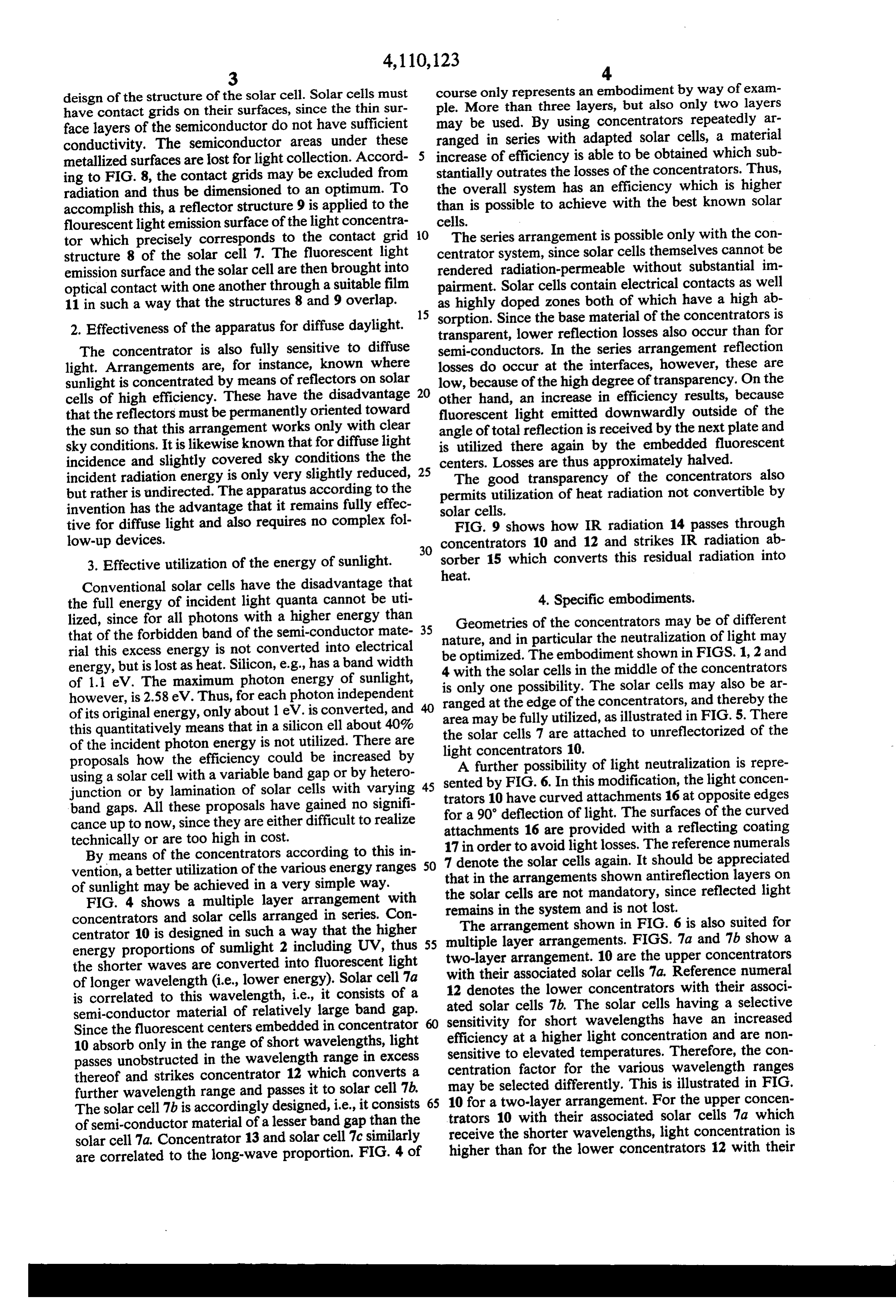
FIG. 4 shows a multiple layer arrangement with the solar cells are not mandatory, since reflected light concentrators and solar cells arranged in series. Con remains in the system and is not lost. The arrangement shown in FIG. 6 is also suited for centrator 10 is designed in such a way that the higher multiple layer arrangements. FIGS. 7a and 7b show a energy proportions of sumlight 2 including UV, thus 55 the shorter waves are converted into fluorescent light two-layer arrangement. 10 are the upper concentrators of longer wavelength (i.e., lower energy). Solar cell 7a 12 denotesassociated with their solar cells 7a. Reference numeral the lower concentrators with their associ is correlated to this wavelength, i.e., it consists of a ated solar cells 7b. The solar cells having a selective semi-conductor material of relatively large band gap. sensitivity for short wavelengths have an increased Since the fluorescent centers embedded in concentrator 10 absorb only in the range of short wavelengths, light efficiency at a higher light concentration and are non passes unobstructed in the wavelength range in excess sensitive to elevated temperatures. Therefore, the con thereof and strikes concentrator 12 which converts a centration factor for the various wavelength ranges further wavelength range and passes it to solar cell 7b, 65 may be selected differently. This is illustrated in FIG. The solar cell 7b is accordingly designed, i.e., it consists tratorsa10 10 for two-layer arrangement. For the upper concen of semi-conductor material of a lesser band gap than the receive thewith their associated solar cells 7a which shorter wavelengths, light concentration is solar cell 7a. Concentrator 13 and solar cell 7c similarly are correlated to the long-wave proportion. FIG. 4 of higher than for the lower concentrators 12 with their
Page 10
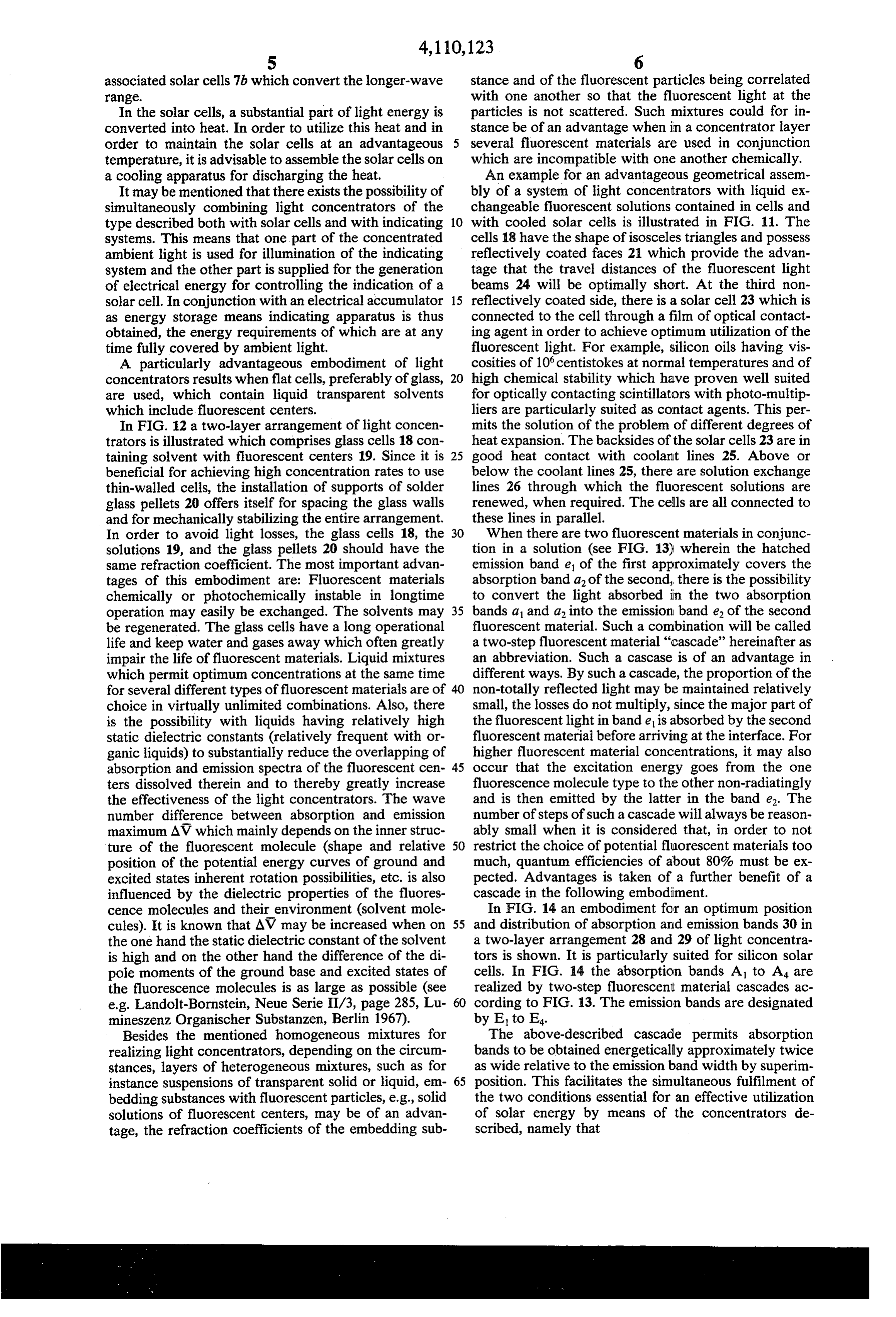
associated solar cells 7b which convert the longer-wave stance and of the fluorescent particles being correlated range. with one another so that the fluorescent light at the In the solar cells, a substantial part of light energy is particles is not scattered. Such mixtures could for in converted into heat. In order to utilize this heat and in stance be of an advantage when in a concentrator layer order to maintain the solar cells at an advantageous several fluorescent materials are used in conjunction temperature, it is advisable to assemble the solar cells on which are incompatible with one another chemically. a cooling apparatus for discharging the heat. An example for an advantageous geometrical assem It may be mentioned that there exists the possibility of bly of a system of light concentrators with liquid ex simultaneously combining light concentrators of the changeable fluorescent solutions contained in cells and type described both with solar cells and with indicating 10 with cooled solar cells is illustrated in FIG. 11. The systems. This means that one part of the concentrated cells 18 have the shape of isosceles triangles and possess ambient light is used for illumination of the indicating reflectively coated faces 2 which provide the advan system and the other part is supplied for the generation tage that the travel distances of the fluorescent light of electrical energy for controlling the indication of a beams 24 will be optimally short. At the third non solar cell. In conjunction with an electrical accumulator 15 reflectively coated side, there is a solar cell 23 which is as energy storage means indicating apparatus is thus connected to the cell through a film of optical contact obtained, the energy requirements of which are at any ing agent in order to achieve optimum utilization of the time fully covered by ambient light. fluorescent light. For example, silicon oils having vis A particularly advantageous embodiment of light cosities of 10 centistokes at normal temperatures and of concentrators results when flat cells, preferably of glass, 20 high chemical stability which have proven well suited are used, which contain liquid transparent solvents for optically contacting scintillators with photo-multip which include fluorescent centers. liers are particularly suited as contact agents. This per In FIG. 12 a two-layer arrangement of light concen mits the solution of the problem of different degrees of trators is illustrated which comprises glass cells 18 con heat expansion. The backsides of the solar cells 23 are in taining solvent with fluorescent centers 19. Since it is 25 good heat contact with coolant lines 25. Above or beneficial for achieving high concentration rates to use below the coolant lines 25, there are solution exchange thin-walled cells, the installation of supports of solder lines 26 through which the fluorescent solutions are glass pellets 20 offers itself for spacing the glass walls renewed, when required. The cells are all connected to and for mechanically stabilizing the entire arrangement. these lines in parallel.
In order to avoid light losses, the glass cells 18, the 30 When there are two fluorescent materials in conjunc solutions 19, and the glass pellets 20 should have the tion in a solution (see FIG. 13) wherein the hatched same refraction coefficient. The most important advan emission band e of the first approximately covers the tages of this embodiment are: Fluorescent materials absorption band a of the second, there is the possibility chemically or photochemically instable in longtime to convert the light absorbed in the two absorption operation may easily be exchanged. The solvents may 35 bands a and a into the emission band e of the second be regenerated. The glass cells have a long operational fluorescent material. Such a combination will be called life and keep water and gases away which often greatly a two-step fluorescent material "cascade' hereinafter as impair the life of fluorescent materials. Liquid mixtures an abbreviation. Such a cascase is of an advantage in which permit optimum concentrations at the same time different ways. By such a cascade, the proportion of the for several different types of fluorescent materials are of 40 non-totally reflected light may be maintained relatively choice in virtually unlimited combinations. Also, there small, the losses do not multiply, since the major part of is the possibility with liquids having relatively high the fluorescent light in band e is absorbed by the second static dielectric constants (relatively frequent with or fluorescent material before arriving at the interface. For ganic liquids) to substantially reduce the overlapping of higher fluorescent material concentrations, it may also absorption and emission spectra of the fluorescent cen 45 occur that the excitation energy goes from the one ters dissolved therein and to thereby greatly increase fluorescence molecule type to the other non-radiatingly the effectiveness of the light concentrators. The wave and is then emitted by the latter in the band e. The number difference between absorption and emission number of steps of such a cascade will always be reason maximum AV which mainly depends on the inner struc ably small when it is considered that, in order to not ture of the fluorescent molecule (shape and relative 50 restrict the choice of potential fluorescent materials too position of the potential energy curves of ground and much, quantum efficiencies of about 80% must be ex excited states inherent rotation possibilities, etc. is also pected. Advantages is taken of a further benefit of a influenced by the dielectric properties of the fluores cascade in the following embodiment. cence molecules and their environment (solvent mole In FIG. 14 an embodiment for an optimum position cules). It is known that AV may be increased when on 55 and distribution of absorption and emission bands 30 in the one hand the static dielectric constant of the solvent a two-layer arrangement 28 and 29 of light concentra is high and on the other hand the difference of the di tors is shown. It is particularly suited for silicon solar pole moments of the ground base and excited states of cells. In FIG. 14 the absorption bands A1 to A4 are the fluorescence molecules is as large as possible (see realized by two-step fluorescent material cascades ac e.g. Landolt-Bornstein, Neue Serie II/3, page 285, Lu 60 cording to FIG. 13. The emission bands are designated mineszenz Organischer Substanzen, Berlin 1967). by E. tO E4.
Besides the mentioned homogeneous mixtures for The above-described cascade permits absorption realizing light concentrators, depending on the circum bands to be obtained energetically approximately twice stances, layers of heterogeneous mixtures, such as for as wide relative to the emission band width by superim instance suspensions of transparent solid or liquid, em 65 position. This facilitates the simultaneous fulfilment of bedding substances with fluorescent particles, e.g., solid the two conditions essential for an effective utilization solutions of fluorescent centers, may be of an advan of solar energy by means of the concentrators de tage, the refraction coefficients of the embedding sub scribed, namely that
Page 11
1. the fluorescence light emission bands provided for 3. A apparatus according to claim 2, wherein an appa light progression within the same layer overlap as little ratus for the absorption and utilization of the heat radia as possible with adjacent absorption bands, and tion passing through the last concentrator is provided 2. the absorption bands of the different layers gap behind said last concentrator.
lessly overlap. 4. An apparatus according to claim 2, wherein the The fact that the absorption coefficient for silicon concentration factor for the shorter wavelength con decreases with increasing wavelength 27 disfavors a centrators is higher than that for the longer wavelength one-layer concentrator arrangement for use with silicon concentrators.
solar cells, so that it is advantageous to convert all pho 10 5. An apparatus according to claim 1, wherein re tons of solar light through plural-step "fluorescent ma flecting structures on the emission surface of the con terial cascades' in a range in the near IR. centrator are correlated to the contact grid geometries The distribution of the spectrum shown in FIG. 14 of the solar cell in such a way that no light is emitted essential only to explain the main aspects. Sunlight uti onto the contact grids of the solar cell. lizable by the silicon solar cell could also be utilized 15 6. An apparatus according to claim 1, wherein said approximately fully in a two-layer arrangement of con intermediary medium has a refraction coefficient of 1. centrators where in each concentrator layer 28, 29 only 7. An apparatus according to claim 1, wherein an one 2-step fluorescent material cascade is used in which - arrangement of two superimposed light concentrators is fluorescent materials are used having accordingly wider used, the shorter-wave proportion of the sun spectrum absorption bands. collected in one light concentrator being used for the For reducing light losses by self-absorption as a result 20 illumination of an indicating apparatus and the remain of overlapping of the emission and absorption band 30 ing longer-wave spectrum range being collected in the of a fluorescent material, there is also the possibility of second concentrator layer and supplied to a solar cell. accommodating the fluorescent material in a thin mar 8. An apparatus according to claim 1, wherein the ginal layer of the light concentrator in an accordingly 25 light concentrators consist of cells which contain solu higher concentration, e.g. in the instance of solid sol tions of liquid transparent solvents with fluorescent vents realizable by diffusing in the fluorescent material CenterS.
or for heterogeneous mixtures of the nature described 9. An apparatus according to claim 8, further com further above by embedding of fluorescent particles in prising transparent glass pellets separating said cells, solid or liquid embedding agents with the same refrac 30 said cells, said solutions and said transparent glass pel tion coefficient. lets having the same refraction coefficient. As a last example of the apparatus of this invention, it 10. An apparatus according to claim 8, wherein said is further set forth how the light concentrator principle solvents consist of liquid mixtures in order to permit in conjunction with indicating apparatus with the con optimum concentrations for a plurality of different currrent use of solar cells is able to be used for an opti 35 types of fluorescent centers at the same time. mum utilization of solar energy. The indicating appara 11. An apparatus according to claim 8, wherein said tus will only use the spectrum range, from blue to green solvents have static dielectric constants of between 5 or yellow in order to utilize the eye's spectral sensitiv and 100.
ity. It is therefore advisable to collect the upper portion 12. An apparatus according to claim 1, wherein said of the sun's spectrum for illumination of the indicator light concentrators consist of layers which are made of via a first concentrator layer and the remaining spec heterogeneous mixtures of transparent solid or liquid trum range in a second concentrator layer behind the substances in which said fluorescent centers are embed first and to feed it to a solar cell for generating electrical ded.
energy for the current supply of the indicator. 13. An apparatus according to claim 12, wherein said The invention may be embodied in other specific 45 transparent embedding substances and said flourescent forms without departing from the spirit of or essential centers have the same refraction coefficient. characteristics thereof. The embodiments are therefore 14. An apparatus according to claim 12, wherein said to be considered in all respects as illustrative and not flourescent centers consist of solid solutions of fluores restrictive. cent materials.
What is claimed is: 50 15. An apparatus according to claim 1, wherein an 1. An apparatus for converting solar energy into arrangement of two superimposed light concentrators is electrical energy, wherein light is collected in a light used, each layer containing fluorescent materials which concentrator comprising a transparent layer, the refrac are correlated to one another in such a way that on the tion coefficient of which is greater than that of the one hand fluorescent light emission bands provided for ambient medium and which contains fluorescent centers 55 light progression within the same layer overlap as little and is fed to a solar cell, characterized in that more than as possible with adjacent absorption bands and on the one concentrator/solar cell combination is stacked on other hand the absorption bands of the different layers top of another through the intermediary of a medium gaplessly overlap.
having a smaller refraction coefficient than that of the 16. An apparatus according to claim 15, wherein the concentrators, each concentrator being adapted to con fluorescent materials are disposed in a thin marginal vert a portion of the incident spectrum into fluorescent layer of the light concentrator.
light and supply it to a solar cell. 17. An apparaus according to claim 16, wherein the 2. An apparatus according to claim 1, wherein the distribution of the fluorescent material in a thin mar concentrators are so arranged that the concentrator ginal layer is produced by fluorescent material diffused upon which radiation strikes first absorbs the shortest 65 into a solid tranparent solvent.
wavelengths, the next to follow absorbs a somewhat 18. An apparatus according to claim 16, wherein the longer wavelength range and the last absorbs the lon distribution of the fluorescent material in a thin mar gest wavelength range. ginal layer is produced by depositing the fluorescent
Page 12
particles in a solid or liquid embedding agent at its mar coated and the solar cells are arranged at the third, non-reflectively coated side.
gin. 20. An apparatus according to claim 19, wherein the 19. An apparatus according to claim 1, wherein the 5 triangular light concentrators are arranged in an area between coolant lines extending parallel to the third light concentrators have the shape of isosceles triangles, side.
the faces of the two equally long sides are reflectively
Provenance
- Collection
- Cited prior art
- Original PDF
- patentimages.storage.googleapis.com →
- Filed
- 1977-05-04
- Pages
- 12
- Method
- pdftotext (the PDF's own text layer) + pdftoppm 300dpi page scans
- Source
- Google Patents bibliographic record
- Granted
- 1978-08-29
- Inventors
- Adolf Goetzberger; Waldemar Greubel; Fraunhofer Gesellschaft zur Foerderung der Angewandten Forschung eV
- Transcribed from
- patentimages.storage.googleapis.com →