patent · US4219074
Method and apparatus for low-loss storage of thermal energy and for low-loss withdrawal of the stored thermal energy
26 August 1980
Page 1 — bibliographic record
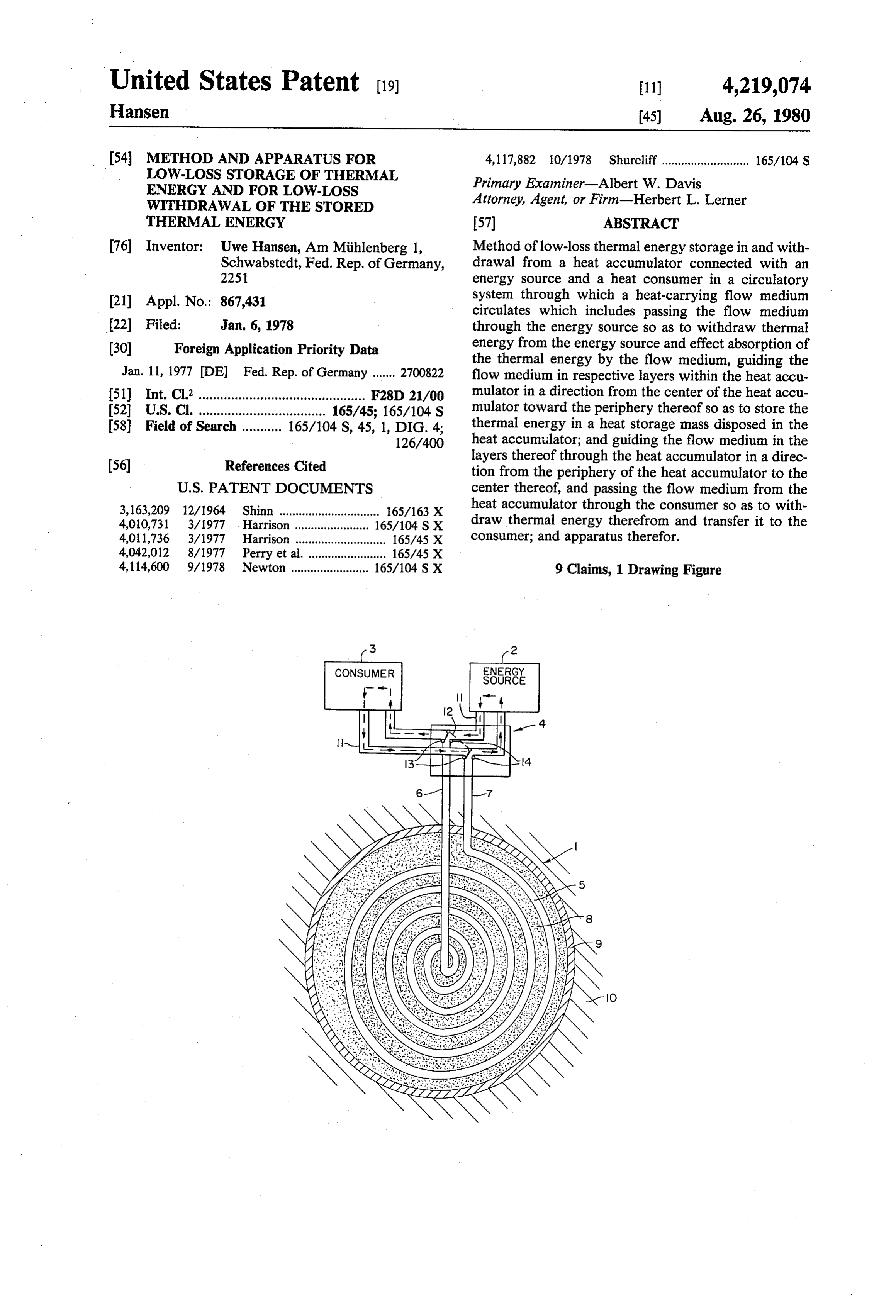
United States Patent (19) 11) 4,219,074 Hansen 45 Aug. 26, 1980 54 METHOD AND APPARATUS FOR 4,117,882 10/1978 Shurcliff ........................... 165/104 S
LOW-LOSS STORAGE OF THERMAL
ENERGY AND FOR LOW.LOSS Primary Examiner-Albert W. Davis
WTHDRAWAL OF THE STORED Attorney, Agent, or Firm-Herbert L. Lerner THERMAL ENERGY (57) ABSTRACT 76 Inventor: Uwe Hansen, Am Miihlenberg 1, Method of low-loss thermal energy storage in and with Schwabstedt, Fed. Rep. of Germany, drawal from a heat accumulator connected with an 2251 energy source and a heat consumer in a circulatory (21) Appl. No.: 867,431 system through which a heat-carrying flow medium circulates which includes passing the flow medium (22 Filed: Jan. 6, 1978 through the energy source so as to withdraw thermal (30) Foreign Application Priority Data energy from the energy source and effect absorption of the thermal energy by the flow medium, guiding the
Jan. 11, 1977 DE Fed. Rep. of Germany ....... 2700822 flow medium in respective layers within the heat accu 51) Int. Cl.’.............................................. F28D 21/00 mulator in a direction from the center of the heat accu 52 U.S. C. ................................... 165/45; 165/104 S mulator toward the periphery thereof so as to store the 58 Field of Search ........... 165/104 S, 45, 1, DIG. 4; thermal energy in a heat storage mass disposed in the 126/400 heat accumulator; and guiding the flow medium in the (56) References Cited layers thereof through the heat accumulator in a direc tion from the periphery of the heat accumulator to the
3,163,209 12/1964 Shinn ....... ... 165/163 X heat accumulator through the consumer so as to with 4,010,731 3/1977 Harrison 165/104 S X draw thermal energy therefrom and transfer it to the 401 1,736 3/1977 Harrison ............................ 165/45 X consumer; and apparatus therefor. 4,042,012 8/1977 Perry et al. ........................ 165/45 X 4,114,600 9/1978 Newton ........................ 165/104 S X 9 Claims, 1 Drawing Figure
Page 2
Drawing sheet — no readable text.
Page 3
withdraw thermal energy therefrom and transfer it to
METHOD AND APPARATUS FOR LOW-LOSS the consumer.
STORAGE OF THERMAL ENERGY AND FOR Through this layer-wise heating of the heat storage LOW-LOSS WITH DRAWAL OF THE STORED mass of the heat accumulator from the inside to the THERMAL ENERGY outer periphery, the heat flow caused by the prevailing temperature gradient in this direction is utilized as use
The invention of the instant application relates to a ful heat until a limit has been reached at which the heat method for low-loss thermal energy storage in and accumulator has become fully heated i.e. the tempera withdrawal from a heat accumulator using a flow me ture is as high at the outer edge of the heat accumulator dium, preferably liquid, which is suitable as a heat car 10 as it is in the core or center thereof. At that instant, a rier. For storing the thermal energy, the flow medium heat loss would occur therein comparatively as high as flows in circulating operation through the energy in the hereinaforementioned heretofore known storage source and the heat accumulator, and for withdrawing device. However, at the instant when thermal energy is the stored thermal energy, in circulating operation withdrawn in the heat accumulator in accordance with through the heat accumulator and the consumer. 15 the method and apparatus of the invention, the flow In conventional systems for storage and withdrawal medium flows from the outer periphery of the heat of stored thermal energy from a heat accumulator, the accumulator layer-by-layer in direction toward the core water which serves as the flow medium for the heat or center, so that the flow medium in which has been transfer simultaneously serves as the heat storage me cooled down by transfer of the thermal energy to the dium. This water is heated up in a tank, usually a steel or 20 consumer, is returned to the outer periphery of the heat concrete tank, serving as the heat accumulator, and is accumulator and thus, the heat flow or flux normally fed to the consumer through local withdrawal in a cir drifting away as heat loss is largely recovered as useful culation process. heat for reheating the flow medium. In this manner, a Because of the relatively high thermal conductivity temperature gradient is generated within the heat accu of the water, assisted by the continuous mixing due to 25 mulator, extending from the core or center to the outer the circulating operation, the water in the tank has the periphery, which becomes ever larger with increasing tendency to provide rapid temperature equalization or withdrawal of thermal energy from the heat accumula equilibrium overall. The greater the temperature gradi tor, so that the temperature difference between the heat ent, accordingly, the greater is the amount of heat storage medium and the wall of the heat accumulator which flows in direction of the temperature drop. Since, 30 becomes ever smaller and the waste heat flow con in this conventional device, the greatest temperature nected therewith even less.
gradient exists, however at the transition between the In accordance with the apparatus for performing the heated water and the wall of the tank, there occurs a method of the invention, there is provided an apparatus continuous flow of heat from the center of the water for low-loss thermal energy storage and withdrawal, tank to the edge of the tank and usefulness of the heat is 35 comprising a pipeline wound layer-wise into a ball-like lost there. structure, the windings of the pipeline having an inter Since this is undesirable, the walls of the tank, accord mediate spacing adequate for accommodating heat-stor ing to the heretofore known heat accumulator, have age mass therein, the pipeline having two ends, one of been provided with a layer of insulation. However, in which is located at the outer periphery of the ball-like order to keep the amount of loss within reasonably 40 structure and the other of which is located at the center justifiable limits, the insulation layers had to be made so of the bale-like structure, a first pipeline union con thick (about 500 mm) that an economical use of such nected to the one end of the pipeline, and a second heat accumulators could hardly be considered to be pipeline union connected to the other end of the pipe feasible from a cost aspect. line.
It is therefore an object of the invention to avoid the 45 In accordance with another feature of the invention, disadvantages of the heretofore known apparatus and also included are valve means for selectively connect method and thus to provide a heat accumulator having ing, on the one hand, the first pipeline union to a pipe heat losses that are as low as possible yet requiring only inlet to an energy source and the second pipeline union a reasonable outlay for insulation. to a pipe outlet from the energy source and, on the other With the foregoing and other objects in view, there is 50 hand, the first pipeline union to a pipe outlet from a heat provided in accordance with the method of the inven consumer and the second pipeline unit to a pipe inlet to tion, a method of low-loss thermal energy storage in the heat consumer.
and withdrawal from a heat accumulator connected In accordance with an added feature of the invention, with an energy source and a heat consumer in a circula the ball-like structure has a substantially spiral configu tory system through which a heat-carrying flow me 55 ration.
dium circulates which comprises passing the flow me In order to achieve a heat flow within the heat accu dium through the energy source so as to withdraw mulator that is as slow as possible, a heat storage me thermal energy from the energy source and effect ab dium of very low thermal conductivity should be used sorption of the thermal energy by the flow medium, which, in addition, should be easily workable and as guiding the flow medium in respective layers within the 60 inexpensive as possible. Therefore, in accordance with a heat accumulator in a direction from the center of the further feature of the invention, the heat-storage mass in heat accumulator toward the periphery thereof so as to the spacing between the pipeline windings is earth. store the thermal energy in a heat storage mass disposed In accordance with an additional feature of the inven in the heat accumulator; and guiding the flow medium tion, the ball-like structure and the heat storage mass in the layers thereof through the heat accumulator in a 65 disposed in the spacing intermediate the pipeline wind direction from the periphery of the heat accumulator to ings forming the ball-like structure constitute a heat the center thereof, and passing the flow medium from accumulator, and the heat accumulator is received in a the heat accumulator through the consumer so as to cavity formed in the earth. In this manner, the hereto
Page 4
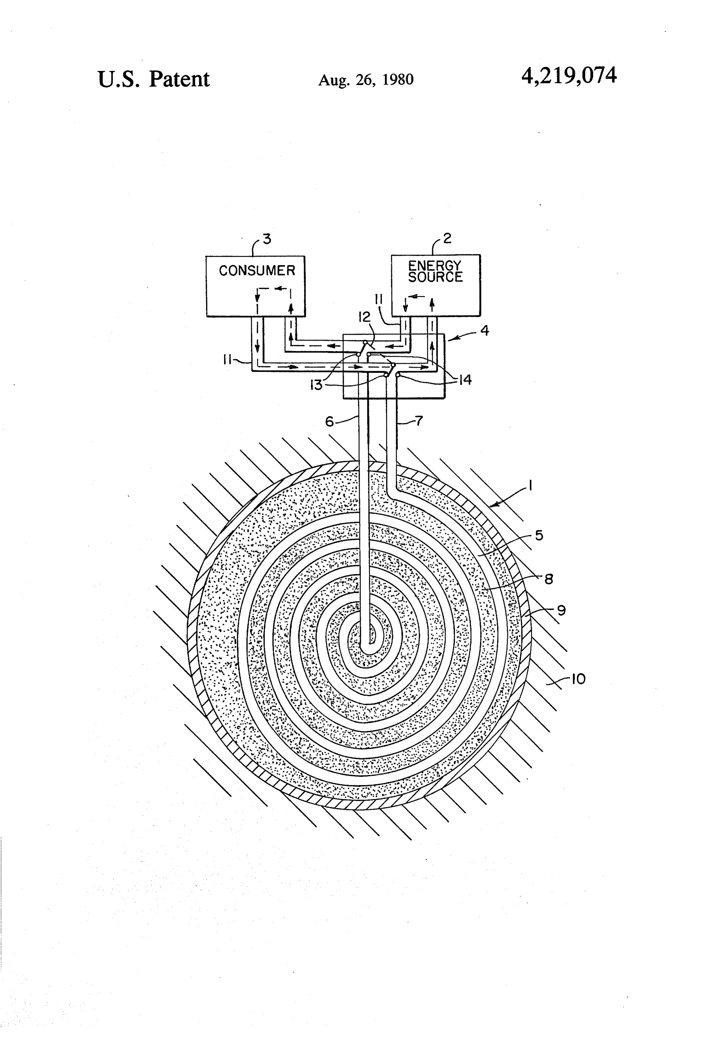
fore conventional and very expensive tank, formed of unions 6 and 7 can be connected, on the one hand, for steel or concrete, becomes unnecessary as supporting storing thermal energy, respectively, to an outlet from structure for the heat accumulator, since the function and an inlet to the energy source 2 and, on the other thereof is assumed by the earth or ground, in accor hand, for surrendering thermal energy, respectively, to dance with the invention. However, in order to effect a an inlet to and an outlet from the consumer 3. This separation between the soil as the heat storage medium selective connection of the heat accumulator 1 to the and the earth as the medium which, as a whole, Sur energy source 2 or the consumer 3 is accomplished by rounds the heat accumulator, in accordance with yet means of the valve control device 4. another feature of the invention, means are provided for The storing process operates as follows: forming a separating layer disposed between the heat 10 For storing thermal energy in the heat accumulator 1, accumulator received in the cavity and the earth defin the valve 12 is shifted into the position 13, as shown in ing the cavity. the drawing, and the circulation of the flow medium In accordance with yet a further feature of the inven between the heat accumulator 1 and the energy source tion, the separating layer is formed of insulating mate 2 is established. Simultaneously, the flow direction of rial. The purpose of these features is to reduce further 15 the flow medium is set and the flow medium, which has yet the already extremely small heat losses.
In order to attain an additional increase in the absorp been heated up by the energy source 2 is conducted tion of thermal energy of the heat accumulator, in ac unions 6 the through
pipe system 11 and the pipe connections or the pipeline 5 into the core or center of the cordance with yet an additional feature of the invention, heat accumulator. Thermal energy which has been ab the heat storage mass contains an intermixed additive of 20 sorbed from the energy source 2 by the heat storage eutectic material.
In accordance with a concomitant feature of the in medium 8, is surrendered by the heat storage medium 8, vention, the additive of eutectic material is concen through the pipeline 5 to the outer periphery of the heat trated at the center of the ball-like structure. accumulator 1. The cooled-off flow medium is then Other features which are considered as characteristic 25 conducted back through the pipe connection or union 7 for the invention are set forth in the appended claims. and the pipe system 1 to the energy source 2. This Although the invention is illustrated and described circulating process is repeated until the heat accumula herein as embodied in method and apparatus for low torThe 1 has stored the desired amount of thermal energy. withdrawal process operates as follows:.
loss storage of thermal energy and for low-loss with
For withdrawal, the circulation of the flow medium drawal of the stored thermal energy, it is nevertheless 30 between not intended to be limited to the details shown, since the heat accumulator 1 and the consumer 3 is various modifications may be made therein without established by shifting the valve 12 into the position 14 thereof which simultaneously interrupts the circulation departing from the spirit of the invention and within the scope and range of equivalents of the claims. through the energy source 2. At the same time, the flow The invention, however, together with additional 35 direction of the flow medium is set opposite to the flow objects and advantages thereof will be best understood direction during the storing process, so that the flow from the following description when read in connection medium heated by the thermal energy stored in the heat with the accompanying drawings, in which: the FIG accumulator 1 is drawn through the pipe connection or URE of the drawing is a diagrammatic sectional view of union 6 of the pipeline 5 from the core or center of the the heat accumulator of the invention. 40 heat accumulator . After the flow medium has surren Referring now to the FIGURE of the drawing, a heat dered thermal energy to the consumer 3, it is returned accumulator 1, according to the invention, is shown through the pipe system 11 and the pipe connection or therein only as a two-dimensional structure to illustrate union 7 of the pipeline 5 to the outer periphery of the the operation thereof. Also shown is an energy source 2, heat accumulator 1. In accordance with the withdrawal a consumer 3 and a valve control device 4 which in 45 of thermal energy from the heat accumulator 1, the flow cludes a valve 12 movable to two selective switching medium travels through the pipeline windings to the positions 13 and 14. Although not shown, suitable con core or center of the heat accumulator 1, again absorb ventional pumping means may also be connected in the ing thermal energy.
circulation system. For clarity of presentation, the There is claimed:
valve 12 is shown as a switch. The heat accumulator 1 50 1. Apparatus for low-loss thermal energy storage and is formed of a pipeline 5 which carries the flow medium withdrawal from a heat accumulator connected with an and is wound in layers in ball-like form and may be energy source and a heat consumer, comprising a pipe generally spiral or irregular in shape. The heat accumu line having flow medium disposed therein and being lator 1 also includes a pipe connection or union 7 at the wound layer-wise into a ball-like structure, the wind outer circumference or periphery of the ball-like struc 55 ings of said pipeline having an intermediate spacing, a ture and a pipe connection or union 6 at the center or heat storage mass disposed in said intermediate spacing, core of the ball-like structure. The pipeline 5 is embed said pipeline having two ends, one of which is located at ded in earth which serves as a heat storage medium 8 the outer periphery of said ball-like structure and the and is surrounded by an insulating layer 9 which other of which is located at the center of said ball-like thereby separates the heat accumulator 1 from the earth 60 structure, a first pipeline union connected to said one or ground 10 surrounding the latter. The heat storage end of said pipeline, and a second pipeline union con means 8 may have eutectic materials admixed which nected to said other end of said pipeline, and means for can be concentrated near the core or center of the ball guiding the flow medium from the energy source like structure. The insulating layer 9 may be formed of through said pipeline from the center to the periphery any suitable thermal insulating material. 65 of said ball-like structure and for subsequently guiding The heat accumulator 1 is connected by the pipe said flow medium through said pipeline from the pe connections or unions 6 and 7 to a pipe system 11. By riphery to the center of said ball-like structure and to way of the pipe system 11, the pipe connections or the heat consumer, whereby thermal energy is trans
Page 5
ferred from the energy source to the heat storage mass ball-like structure constitute a heat accumulator, and and from the heat storage mass to the consumer. said heat accumulator is received in a cavity formed in 2. Apparatus according to claim 1 including valve the earth.
means for selectively connecting, on the one hand, said 6. Apparatus according to claim 5 including means first pipeline union to a pipe inlet to the energy source forming a separating layer disposed between said heat and said second pipeline union to a pipe outlet from the accumulator received in said cavity and the earth defin energy source and, on the other hand, said first pipeline ing said cavity.
union to the pipe outlet from the heat consumer and said 7. Apparatus according to claim 6 wherein said sepa second pipeline unit to a pipe inlet to the heat consumer. rating layer is formed of insulating material. 3. Apparatus according to claim 1 wherein said ball 10 8. Apparatus according to claim 1 wherein said heat like structure has a substantially spiral configuration.
4. Apparatus according to claim 1 wherein the heat storage mass contain an intermixed additive of eutectic storage mass in the spacing between said pipeline wind material.
ings is earth. 9. Apparatus according to claim 8 wherein said addi 5. Apparatus according to claim 1 wherein said ball 15 tive of eutectic material is concentrated at the center of like structure and said heat storage mass disposed in the said ball-like structure.
spacing intermediate the pipeline windings forming said k k sk k
Provenance
- Collection
- Cited prior art
- Original PDF
- patentimages.storage.googleapis.com →
- Filed
- 1978-01-06
- Pages
- 5
- Method
- pdftotext (the PDF's own text layer) + pdftoppm 300dpi page scans
- Source
- Google Patents bibliographic record
- Granted
- 1980-08-26
- Inventors
- Uwe Hansen
- Transcribed from
- patentimages.storage.googleapis.com →