patent · US2886620
Method and apparatus for making positive battery plates
12 May 1959
Page 1
May 12, 1959 E. L. BARRETT 2,886,620
METHOD AND APPARATUS FOR MAKING POSITIVE BATTERY PLATES
Filed July 12, 1954 2. Sheets-Sheet l Saa 4.
ceae au/zza
Sever Orvae
e. aro J.4 Acol,
dullau, flav, YW f
Page 2
Drawing sheet — no readable text.
Page 3
United States Patent Office Patented May 12, 1959
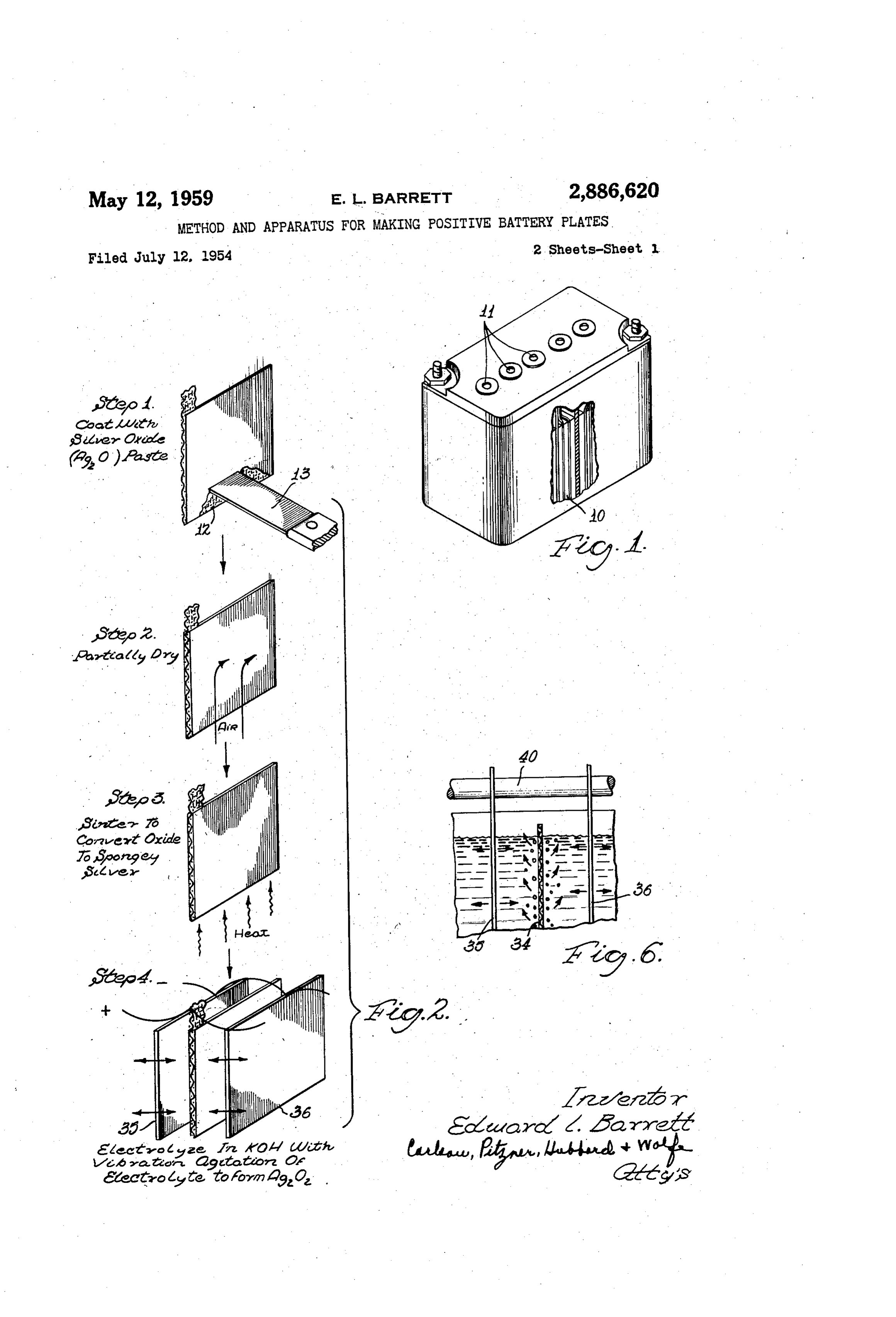
cedure which I employ for making the positive plates has been found to be an important factor in establishing such characteristics. A typical battery consisting of five 2,886,620 cells is shown in Fig. 1. Each of the cells has a bundle 10 of positive and negative plates, for example, five posi
METHOD AND APPARATUS FOR MAKING tive and six negative, separated by suitable porous sepa POSTIVE BATTERY PLATES rators. The positive plates, with which this invention is Edward L. Barrett, La Grange, Ill. concerned, have bi-valent silver oxide as the active ma terial, while the negative plates are formed of spongy
Application July 12, 1954, Serial No. 442,696 O zinc. The battery is stored in the dry condition and just 5 Claims. (Cl. 136-34) before use electrolyte is added through an opening 1 at the top of each of the cells. The amount of electrolyte is purposely quite limited, most of it being absorbed by the porous separators so that each cell contains a rela
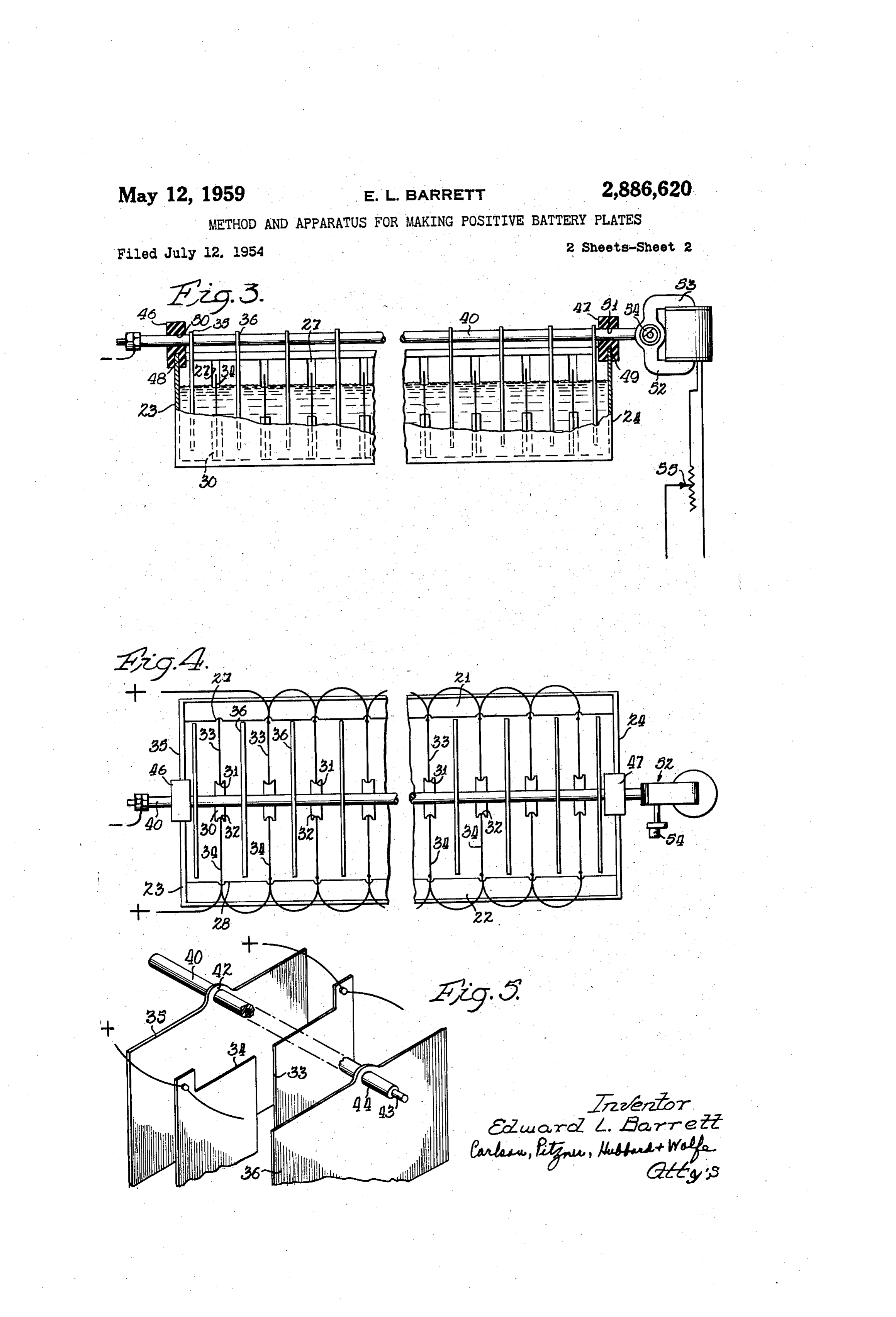
The present invention relates to battery plates, and 5 tively small amount of free electrolyte. In Fig. 2 the steps which I employ in producing a more particularly to a procedure for producing a positive plate for use in batteries of the silver-zinc-alkali type. positive plate are graphically illustrated in the form of a It is an object of the present invention to provide an flow diagram. The first step consists in applying a paste improved method of preparing positive plates, resulting of silver oxide, AgO, to a metal grid 12 measuring ap in plates which are more uniform than prior plates in 20 proximately 2 inches by 2 inches. Preferably the grid their physical and chemical characteristics and which is formed of silver screen or mesh, and the paste is ap enable production of high output batteries which are plied to both sides by a spatula 13, as shown. Silver consistent and reliable in operation. It is another ob is preferred, since it is so closely related to the active ject to provide an improved procedure for preparing plate material, bi-valent silver oxide, which is formed in positive plates which enables high quality plates to be 25 the final or electrolyzing step. In mixing the paste, silver produced much more quickly than before. It is a re oxide powder of high purity is used, mixed with water lated object to provide an improved method which enables which has been distilled and de-ionized. The consistency the current density during the charging operation to be of the paste is relatively unimportant and is a matter increased beyond that which can normally be tolerated, which may be left to the discretion of the operator. The but without any tendency of the plates to throw off par 30 paste should be applied in an even coat, filling all of the ticles of active material. It is still another object, related interstices except for the connecting tab, with the high to the foregoing, to provide a method of producing a points of the wire mesh serving as a convenient guide for positive plate which results in a more even distribution the applied edge of the spatula. of current between parallel-connected plates, enabling the Following the coating operation, the plates are allow plates to keep in step with one another during the elec 35 to “dry” in contact with moving air and at room tem trolyzing process. Finally, it is an object to provide a perature, for a period of several minutes, in order to novel device for carrying out the improved method. remove the excess moisture in the paste. The plates are Other objects and advantages of the invention will be not dried completely in this step, but sufficient moisture come apparent upon reading the attached detailed descrip is removed so as to prevent violent or excessive steam tion and upon reference to the drawings, in which: 40 ing when the plate is subjected to an elevated tempera Figure 1 shows in perspective a battery of the type ture in the following step. It is found that where this to which the present invention is applicable, with a por partial drying step is omitted, the escaping steam tends tion of the case broken away to show the internal con to form minute fissures and craters in the coating which struction. impair the operating characteristics of the final plate. Fig. 2 is a flow diagram setting forth the steps which 45 In step 3 of my procedure the plates are sintered by are preferably employed in producing a positive battery placing them in an oven at 400 C., which converts the plate. paste to spongy silver. The plates are left in the oven Fig. 3 is an elevation in partial section showing ap for approximately 10 minutes, or until it is noted that a paratus employed in carrying out the present invention. white and adherent layer of pure, spongy silver has been Fig. 4 is a plan view of the device shown in Fig. 2. 50 formed. A reducing atmosphere may be used to facili Fig. 5 is a fragmentary perspective showing a pair of tate conversion but it has not been found necessary in vibrated electrodes with battery plates arranged side by practice to take any special steps in this regard. Following this, the plate is electrolyzed, i.e. subjected side between them.
Fig. 6 is a fragmentary elevation showing the dissipa to electrolytic oxidation in a solution of five percent tion of hydrogen gas during the electrolyzing process. 55 potassium hydroxide, using inert negative electrodes, and While the invention has been described herein in con with the electrolyte subjected to vibration generally per nection with a preferred embodiment of the method and pendicular to the positive plates. In practice the in a preferred embodiment of the device for carrying out vention, the vibrated area of the electrolyte should ex the method, it will be understood by one skilled in this tend over the entire presented area of the plates being art that the invention is not necessarily limited thereto, 60 electrolyzed. In the preferred procedure waves of vibra but would include various modifications and alternatives, tion in the electrolyte should be applied to both sides the invention being limited only by the spirit and scope of the plate simultaneously and from sources that are of the claims appended hereto. out of phase relative to the surfaces of the positive plate The silver-zinc-alkali type of battery has character being acted upon.
istics which make it suitable for use in specialized appli 65 The frequency of the vibration, as well as the amplitude, cations such as guided missiles, where large amounts of should be sufficiently high so as to effectively and im power are required for short spaces of time, power on the mediately dislodge bubbles forming on the surface of the order of 250 watts for a period of several minutes, positive plate during electrolyzing. In practice, I and with the battery limited to a volume of less than 10 have employed a frequency of approximately 100 to ap cubic inches. The battery to be described below should 70 proximately 500 vibrations per second and with a total have absolute reliability and a high degree of con excursion at the source of the vibration of approximately sistency between production units. The improved pro 0.020 inch. There is no definite upper limit to the am
Page 4
plitude of the vibration, since the amplitude which may capable of adjustment, both with respect to the frequency be used depends to some degree upon the frequency. It of vibration and the amount of excursion. These re is obviously possible to increase the amplitude to a point quirements are met by providing a small induction-type which will produce frothing and spillage of the electrolyte motor 53 having an eccentric weight 54 mounted on its and possibly damage to the positive plates. Where the shaft. It will be apparent to one skilled in the art that frequency is kept relatively low, for example, on the order the excursion may be controlled by varying the amount of 100 vibrations per second, I propose that the maximum and eccentricity of the weight 54, while the frequency excursion be not higher than, say, 0.100 inch. In prac may be adjusted by varying the applied voltage, for tice, I prefer to keep the amplitude sufficiently low so as example, by a rheostat 55.
to be barely evident on the surface of the electrolyte During the electrolyzing process the vibrator 52 may adjacent the positive plate. An excursion of 0.020 of an be adjusted to produce a total excursion of the negative inch has been successfully employed in production runs plates of approximately 0.020 inch at a frequency of with a frequency of 400-500 vibrations per second. 400 to 500 vibrations per second. The positive plates, While the vibration may be set up in the electrolyte being anchored in the walls of the tank 20, are main by any desired means to obtain prompt and efficient re tained stationary. Since all of the negative plates are moval of the bubbles and the production of more con vibrated in unison, it will be apparent that waves of sistent and reliable positive plates, I prefer to set up such vibration will be set up in the electrolyte for application vibration by vibrating the negative plates which are ar simultaneously over the entire area of the positive plates ranged opposite the positive plates and spaced therefrom, and with the waves applied to the opposite sides of the vibrating all of the negative plates simultaneously during 20 positive plates being out of phase with respect to one the entire course of the electrolyzing procedure. This another.
is accomplished employing the setup shown in Figs. 3 The advantages of the present method and apparatus and 4 and as further detailed in Figs. 5 and 6. will be apparent upon comparing the result with that Referring to Figs. 3 and 4, an electrolyzing tank is in previously obtained in the absence of vibration. Obser dicated at 20 having side walls 25, 22 and end walls 23, 25 vations on a conventional electrolyzing arrangement 24. Means are provided within the tank 20 for supporting showed that certain of the plates produced gas bubbles a series of positive plates which have been coated with immediately, indicative of current flow, while others pro silver oxide and sintered as described above. The sup duced little or no gas bubbles until after the electrolyzing porting means includes a series of notches 27, 28 formed process had been under way several hours. Furthermore, in the inside walls of the tank. 20. Vertically arranged 30 it was noted that the gas bubbles tended to form on the within the tank and in alinement with the notches 27, 28 plates in irregular patches. The resulting positive plates are Supporting posts 30 having registering notches 31, 32. had an uneven appearance, the surface of the plates The tank is preferably of such width as to receive pasted apparently indicating that the electrolyzing process had positive plates within the notches 27, 31 and 28, 32, been carried to a higher degree on some of the plates and respectively. The first two positive plates 33, 34 will be 35 on some areas of the plates than on others. This uneven taken as representative. ness was attributed to variations in electrical resistance in Arranged on the opposite sides of the positive plates the various parallel branches of the electrolyzing circuit 33, 34 and spaced therefrom are inert negative plates 35, and to the insulating or “barrier' effect of the collected 36. The latter plates are preferably about twice the size gas bubbles.
of the positive plates and "cover” substantially the entire 40 When the plates are vibrated in accordance with the area of the latter. The negative plates are preferably present invention, a rather striking difference is noted. formed of metal which is relatively inert in the solution In the first place, all of the positive plates begin gassing, of electrolyte. For this purpose I prefer to use stainless i.e., producing bubbles, promptly as the electrolyzing steel, with the plates spaced approximately 4 inch from current is turned on. Furthermore, it is found that the the positive plates. In a production setup I have used 45 bubbles are jarred loose and escape to the surface prac 14 negative plates to electrolyze 26 positive plates, al tically as fast as they are formed. The tendency of though it will be apparent that more plates may be used bubbles to collect at localized areas on the plate is en in a single tank. tirely eliminated. After electrolyzing is complete, and In carrying out the present invention, the negative upon conversion of all of the silver to bi-valent silver plates are mounted on a common longitudinal support 50 oxide, the plates are removed from the electrolyzing tank which is axially vibrated so as to set up vibrations in the and dried. In appearance they are much more uniform electrolyte which are applied simultaneously over the than the plates previously obtained, indicating that con entire area of the positive plates and in a direction at version to bi-valent silver oxide has occurred evenly and right angles to the positive plates. In the present device thoroughly throughout the area of the plate. the longitudinal support is in the form of a rod 40 which 55 The time required for electrolyzing may be substan rigidly engages the top edges of all of the negative plates.
If desired, the positive plates may be provided with up tially been reduced as a result of the vibrating step. It has common practice in this field to electrolyze the standing tabs 42 which are appropriately punched to plates for periods of more than twenty hours at currents receive a cylindrical rod 43 and with the negative plates of about 150 milliamperes per positive plate. Such long being separated by suitable spacers 44 (see Fig. 5). To 60 periods have been considered necessary in order to be floatingly support the longitudinal member on the tank sure that all of the Spongy silver is converted to the bi 20, mounts 46, 47 made of rubber or similar resilient valent oxide form. Because of the fact that each of the material are employed. These mounts are preferably plates, using the present procedure, begins to electrolyze notched, as indicated at 48, 49, and are slipped over the immediately and in step with all of the other plates, and upstanding end walls 23, 24 of the tank. The support for a number of other reasons which are peculiar to the ing member 40 may be secured to the resilient mounts present procedure and which have not as yet been fully 46, 47 by providing the mounts with openings 50, 5E, investigated, heavier electrolyzing currents may be em in which the supporting member 40 is inserted, as shown ployed and the electrolyzing time may be substantially in Fig. 3. Such resilient support enables the negative reduced. The reduction in time is particularly striking plates to be symmetrically positioned relative to the posi 70 where the electrolyzing current is applied beginning with tive plates, yet permits all of the negative plates to be a low conventional value, and gradually increasing in vibrated positively in unison. The piates may be of 20 magnitude to a half ampere or more as the electrolyzing gauge stock and thus relatively rigid. progresses. In practical production the time may be sub For the purpose of vibrating the member 40 a vibrator stantially halved and satisfactory positive plates have 52 is attached to one end. Such vibrator should be 75 been reduced in certain instances less than three hours.
Page 5
It has further been found that where the above procedure vibrating the support to set up vibrations in the electro is employed, the plate remains intact and substantially no lyte at right angles to the surfaces of said active plates. particles of active material are to be found in the form 4. A device for electrolytically oxidizing battery plates 'of a deposit or sludge at the bottom of the electrolyzing which comprises an electrolyte tank, means for support tank at the end of the run. 5 ing a series of active plates therein parallel to and spaced Batteries constructed using plates as formed above have from one another, a series of chemically inert plates been found to have uniform characteristics resulting in spaced for interleaving with said active plates and dimen high output and a high degree of reliability, making the sioned to cover the entire area of said active plates, a batteries particularly advantageous for use in guided longitudinal support for engaging each of said inert plates missiles or the like. O along its upper edge so that all of said inert plates form What I claim is: a rigid unit with said support, means for longitudinally 1. The method of producing a battery plate having a vibrating the support to set up vibrations in the electro lyte at right angles to the surfaces of said positive plates, bi-valent oxide of a noble metal as the active material which includes electrolytically oxidizing a base of porous and means for resiliently mounting the support on said spongy noble metal by supporting the base in a station tank for relative vibrating movement. 5. The method of producing a battery plate having ary position while setting up vibrations in the electrolyte over substantially the entire plate area which have a fre divalent silver oxide as the active metal comprising the quency and amplitude sufficient to dislodge the bubbles steps of coating an electrically conductive metal grid with silver oxide in the form of a paste, drying the plate of gas formed thereon.
2. A device for electrolytically oxidizing positive bat 20 and paste in a current of air, heating the plate in an oven until the paste is converted to spongy silver, elec tery plates which comprises an electrolyte tank, means trolytically for supporting a series of positive plates therein parallel oxidizing the plate with the plate being the to and spaced from one another, a series of interleaved settingpositive electrode, and, while electrolytically oxidizing negative plates dimensioned to cover the entire area of up vibrations in the electrolyte over substantially said positive plates, a longitudinal support for engaging 25 the entire plate area while maintaining the plate stationary. each of said negative plates along its upper edge so that all of said negative plates form a rigid unit with said References Cited in the file of this patent support, and means at the end of the Support for longi UNITED STATES PATENTS tudinally vibrating the same to set up vibrations in the 30 874,374 Muller et al. ----------- Dec. 17, 1907 electrolyte at right angles to the surfaces of said positive 948,056 King ----------------- Feb. 10, 1910 plates. 2,177,877 Pfaffmann ------------- Oct. 31, 1939 3. A device for electrolytically oxidizing battery plates 2,700,693 Fischbach ------------- Jan. 25, 1955 which comprises an electrolyte tank, means for support 2,721,834 Koury ---------------- Oct. 25, 1955 ing a series of active plates therein parallel to and spaced 35 2,744,860 Rines ----------------- May 8, 1956 from one another, a series of chemically inert plates for 2,746,732 Guillette -------------- May 22, 1956 interleaving with said active plates and dimensioned to cover the entire area of said active plates, a longitudinal FOREIGN PATENTS support for engaging each of said inert plates along its 557,386 Great Britain ----------- Nov. 18, 1943 upper edge so that all of said inert plates form a rigid 40 unit relative to said support, and means for longitudinally
Provenance
- Collection
- Cited prior art
- Original PDF
- patentimages.storage.googleapis.com →
- Filed
- 1954-07-12
- Pages
- 5
- Method
- pdftotext (the PDF's own text layer) + pdftoppm 300dpi page scans
- Source
- Google Patents bibliographic record
- Granted
- 1959-05-12
- Inventors
- Edward L Barrett
- Transcribed from
- patentimages.storage.googleapis.com →