patent · US4159736
Method of and arrangement for the seasonal storage and use of hot water produced in particular by electrical power-generating thermal and nuclear stations
3 July 1979
Page 1 — bibliographic record
United States Patent (19) 11) 4,159,736 Denis et al. (45) Jul. 3, 1979
METHOD OF AND ARRANGEMENT FOR
SEASONAL STORAGE AND USE OF
HOT WATER PRODUCED IN PARTICULAR U.S. PATENT DOCUMENTS
BY ELECTRICAL POWER-GENERATING 3,077,190 2/1963 Allen .................................... 126/271 THERMAL AND NUCLEAR STATIONS 3,851,495 12/1974 Lahoud et al. ........................ 165/45 3,996,749 12/1976 Denis et al. ............................ 60/659 4,010,731 3/1977 Harrison ...... ... 126/400 75 Inventors: Louis H. D. Denis, Puteaux-Bellini; 4,024,910 5/1977 Werner .................................. 165/45 Abel J. H. Bedue, Versailles; Jacques 4,031,952 6/1977 Contour ............... ... 165/104 S Malherbaud, Chatou, all of France
Primary Examiner-Ronald H. Lazarus 73) Assignee: Technip, Rueil-Malmaison, France Assistant Examiner-P. S. Lall Attorney, Agent, or Firm-Frishauf, Holtz, Goodman (21) Appl. No.: 668,000 and Woodward
22 Filed: Mar. 18, 1976 A large capacity tank for the seasonal storage of hot 30 Foreign Application Priority Data water from electrical power-generating thermal and nuclear plants to be used seasonally to heat buildings,
Mar. 20, 1975 FR France ................................ 7508747 consisting of a large basin which comprises partitions Jun. 19, 1975 FR) France ................................ 75 19253 dividing the basin into several portions communicating Aug. 27, 1975 FR) France ................................ 75 26419 with each other in parallel and/or series relationship, at least one hot water supply input from said plants, lead 51) Int. C.’........................ F28D 17/04; F24H 7/00; ing to the distribution systems which open into one FOK 3/02 portion of the basin and at least one cold make-up and 52 U.S. Cl. .................................. 165/104 S; 60/659; /or return water supply input for the distribution sys 126/400; 165/45; 165/DIG. 4 tems opening into another portion of said basin.
165/DIG. 21; 126/400, 271; 60/659 6 Claims, 22 Drawing Figures
Page 2
Drawing sheet — no readable text.
Page 3
Drawing sheet — no readable text.
Page 4
Drawing sheet — no readable text.
Page 5
Drawing sheet — no readable text.
Page 6
Drawing sheet — no readable text.
Page 7
Drawing sheet — no readable text.
Page 8
Drawing sheet — no readable text.
Page 9
structure such as gravel and pebbles or the like. When
METHOD OF AND ARRANGEMENT FOR THE covering the top surface of said porous structure of said SEASONAL STORAGE AND USE OF HOT WATER basins with an impervious, that is leakage-proof or fluid PRODUCED IN PARTICULAR BY ELECTRICAL tight layer made for instance from concrete or asphalt, POWER-GENERATING THERMAL AND it is possible to subsequently cover said surface with NUCLEAR STATIONS tillable soil or tilth which will enable to grow or farm various plants under glass or in greenhouses in any
BACKGROUND OF THE INVENTION season the glasshouses or greenhouses being heated by The present invention relates to a method and to the losses or wastes, adjusted to a desirable extent, of a plants or arrangements enabling for seasonal storage 10 part of the heat stored within the basins. Such an ap and use of hot water produced in particular by electrical proach seems to be very advantageous in the case power-generating thermal and nuclear plants or sta where the porous structure of pebbles or gravel is al tions. ready available on the spot, in particular along some The Applicant has already disclosed previously in river valleys.
1975 entitled Method and Plants for Producing Storing, hand, other approaches may be contemplated advanta "Modulating and Distributing Energy” now U.S. Pat. geously.
No. 3,996,749, means adapted to use in particular for Thus for instance the tank may be designed so that district heating purposes and for various industrial ap the storage areas or portions to which are leading the plications the huge amounts of heat presently wastefully 20 hot water supply systems of the power stations and lost or discharged to the detriment of the ecology from electrical power-generating thermal and nuclear sta those to which are leading the cold make-up and/or return water supply inputs from the utilization systems tions. The invention forming the subject matter of the are in contact with one another while being separated above-mentioned U.S. patent actually enables to multi by at least one movable, yielding or deformable mem ply with a factor usually ranging from 1 to 5 and ac 25 brane or like diaphragm which separates said storage cording to the operating requirements and lay-out con areas into at least one hot water storage body or space ditions the available power supplied by the existing and at least one cold water storage body or space which power plants consuming given amounts of fuel. added together form a substantially constant volume of The present invention brings about new improve storage water. When proceeding that way it is possible ments to such kinds of arrangements by enabling in a 30 to provide within a basin economical structures en particularly convenient, effective, economical and prof abling the storage of hot water and cold water the sub itable manner the seasonal storage of the excess heat power generated by in particular thermal and nuclear stantially problems invariable volumes of which will avoid any which could be raised or encountered with plants during the warm season (extending in particular large capacity seasonal storages of water and variations from the beginning of April to the end of August) and 35 in the filling levels of the basins. the use of these heat excesses more particularly during In such a case and according to a preferred form of the cold season (in particular between October and the the invention, the upper storage portions have an insu end of January). lating roof above which is provided a water surface or SUMMARY OF THE INVENTION lake or pool the bottom of which is said roof. Thus is An arrangement according to the invention enabling economically provided an artificial lake the water sur such a seasonal storage comprises in particular a large face of which may be tempered at will and used for instance for fish-farming or fish-breeding purposes, for capacity tank which is characterized in that it comprises aquatic sports purposes and so on. a basin having a large area, provided substantially on According to the invention, there is moreover pro ground level and comprising partition walls dividing 45 vided a method of using or working and operating a the basin into several portions which communicate with tank of the aforesaid kind wherein water with a specific one another in parallel and/or in series connected rela gravity or density and/or saltness lower than those of tionship, at least one hot water supply input from said said storage hot and cold water is used for filling up the power stations leading to the utilization or distributing holding space of said lake or water surface. Thereby is systems opening into one portion of the basin and at 50 automatically achieved the building up of overlying least one cold make-up and/or return supply input from strata or layers in the upward direction which is nor the utilization or distributing systems opening into an mally the following from bottom to top: cold water other portion of said basin. The separating portions storage of higher density or specific gravity, hot water advantageously exhibit very great lengths with respect storage of intermediate density or specific gravity, cold to their widths and to their depths and communicate 55 lake water of lower density or specific gravity. The hot with each other in parallel and/or in series connected storage water is thus entrapped between two relatively relationship with their adjacent longitudinal ends. It is .
thus possible, provided that there are a minimum num cold or warm water layers which will prevent heat losses to the atmosphere and to the ground owing to the ber of systems or pipe-lines and a minimum number of pumps, to provide in an effective and economical man 60 low conductivity from one water layer to another one when such layers may not become mixed together due ner on surfaces of relatively reduced areas seasonal to the provision of a separating membrane or dia storages of huge amounts of heat which may afterwards phragm. Said membrane may advantageously comprise be recovered during the desired time periods in particu a yielding, deformable, perfectly imputrescible film or lar for purposes of heating buildings as well as for meet layer of plastic material such for instance as polyethyl ing other industrial needs. 65 ene or others of low cost.
According to another novel characterizing feature of Above the storage body of hot water, whether salt or the present invention said basins for the storage of hot not, there is always arranged a "roof which provides water are filled with a mechanically strong porous for some heat insulation of the stored hot water with
Page 10
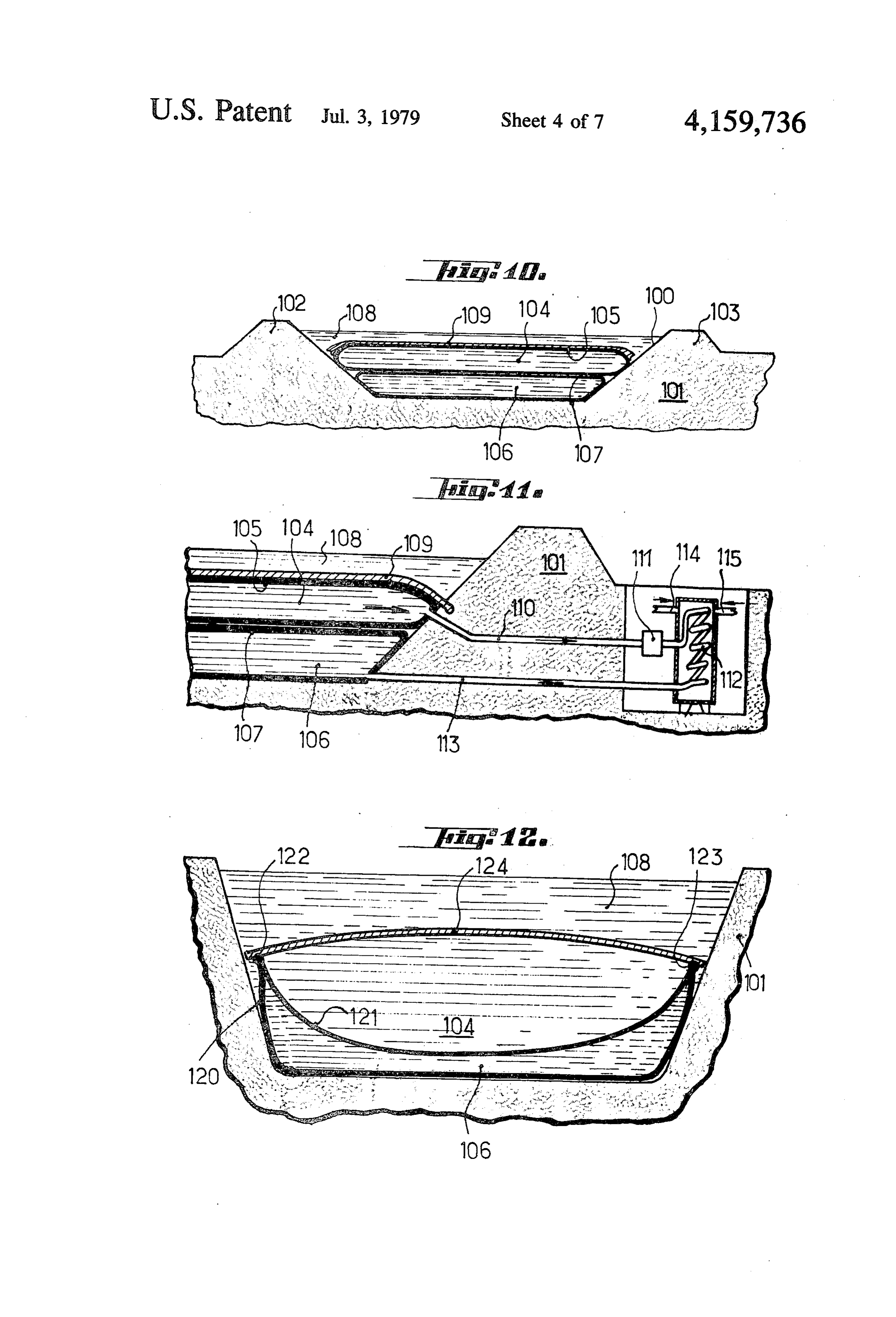
respect to the upper outside environment. Various FIG. 10 is a diagrammatic view in cross-section forms of such roofs will be described. With the word through a tank according to an alternative embodiment; "roof' is meant any covering or disposed above the hot FIG. 11 shows on a larger scale a detail construction water storage body, it being understood that other ele of the connections at one for instance longitudinal end ments according to the embodiments used may be pro of the tank basin and of the heat distributing system vided above this covering. leading from the tank;
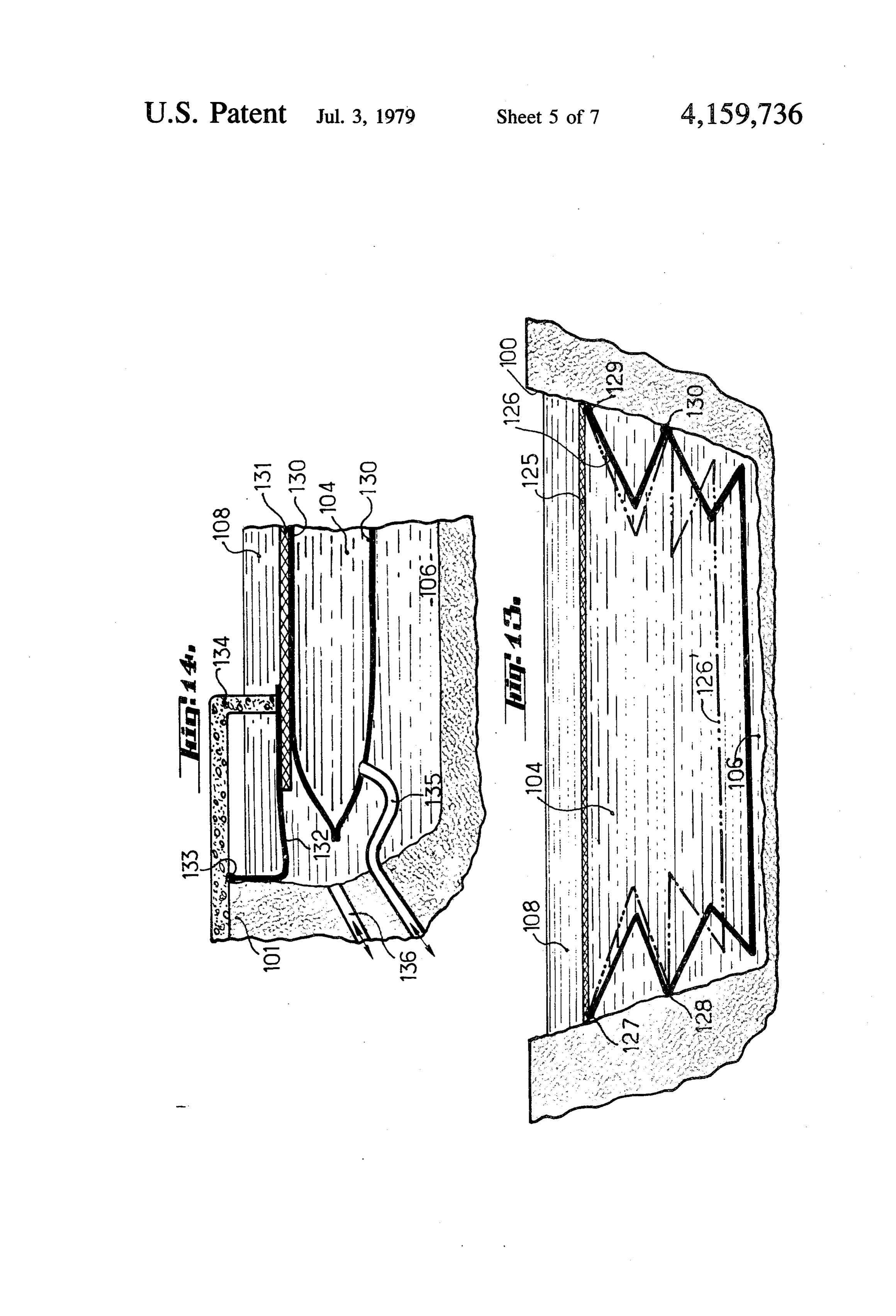
According to an embodiment of the invention the FIGS. 12 and 13 are diagrammatic cross-sectional structure of the insulating "roof” is designed so as to views showing tanks designed according to two other enable not only to compensate for the heat losses of the alternative embodiments, respectively; tank towards the outside environment but also in addi O FIG. 14 illustrates on a larger scale a detail of the tion to supply the hot water storage with additional connection of the hot water and cold water storage thermal energy which is taken from the outer light tanks with the outside as well as a detail of the fastening radiation-that is, from solar energy locally available. means for the insulating roof of the storage means; Thus, according to an embodiment the upper part of FIG. 15 is a cross-sectional view of a storage tank the tank comprises a roof underneath which is stored 15 designed according to another embodiment of the in the hot water, which roof will promote the inward flow vention;
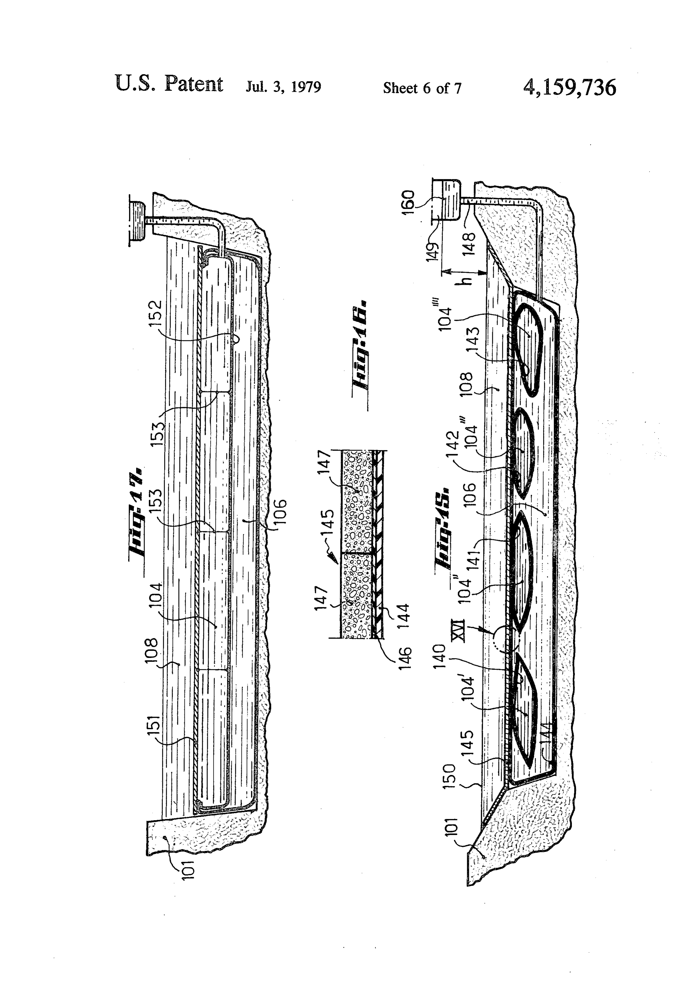
of outside heat due to solar radiation towards the hot FIG. 16 shows on a larger scale the encircled detail water storage and reduce the outward directed flow of part XVI in FIG. 15;
heat from the storage towards the outside. FIG. 17 is a cross-sectional view illustrating another The roof advantageously comprises for this purpose 20 modification;
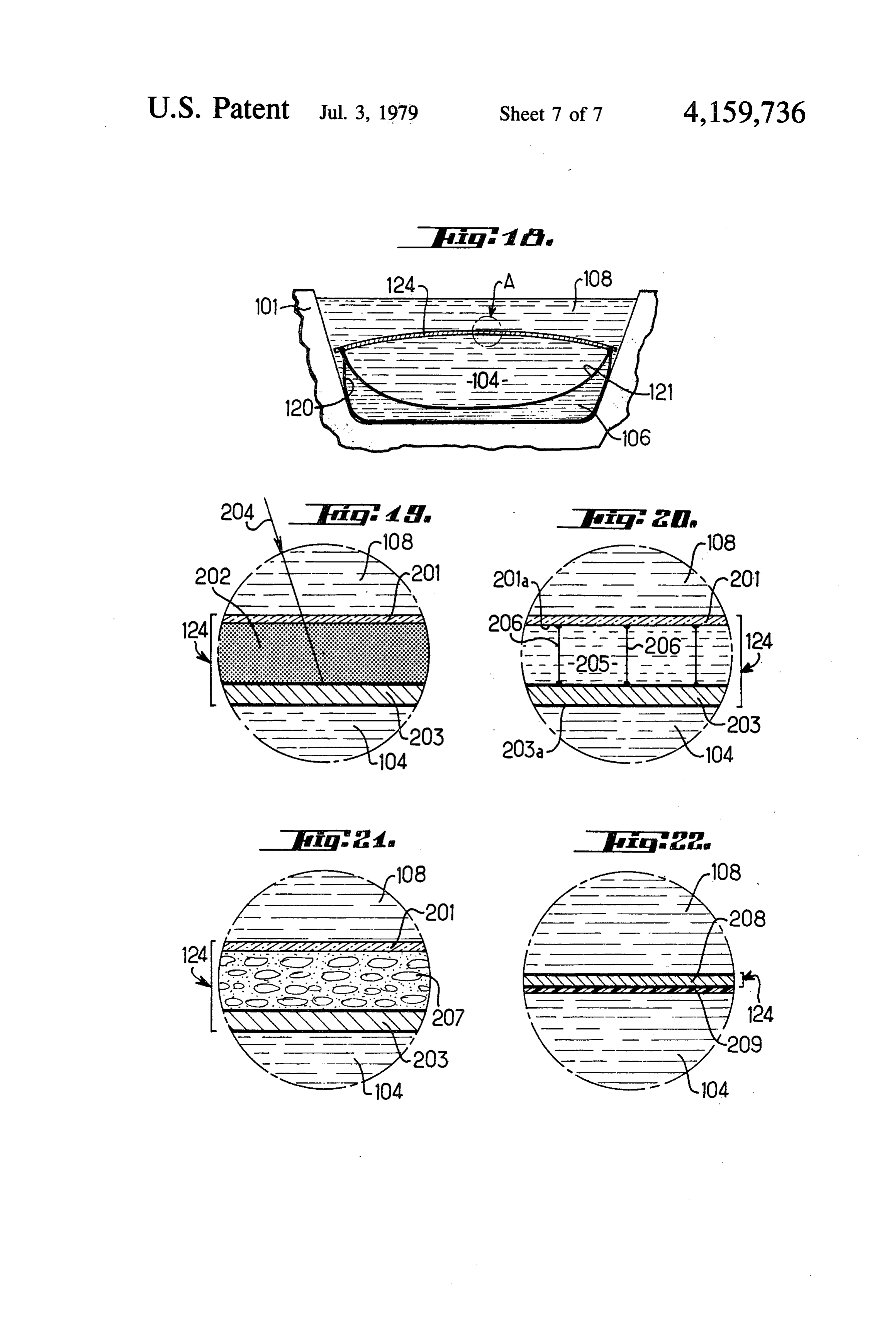
at least one light radiation absorbing layer contacting FIG. 18 is a diagrammatic cross-sectional view show the hot water storage and at least one top layer allowing ing a tank of the kind described in said U.S. Pat. No. the major part of the light flux to travel therethrough 3,996,749; and and reflecting the major part of the infra-red radiation FIGS. 19 to 22 are sectional views of the encircled re-emitted by said absorbing layer. Thus is achieved a 25 part Ain FIG. 18, drawn on a larger scale and diagram hay box-type absorption and confinment effect which matically showing various tank roof constructions for generally enables to compensate for the heat losses from practicing the improvements forming the subject matter the storage towards the outer environmental medium of the invention.
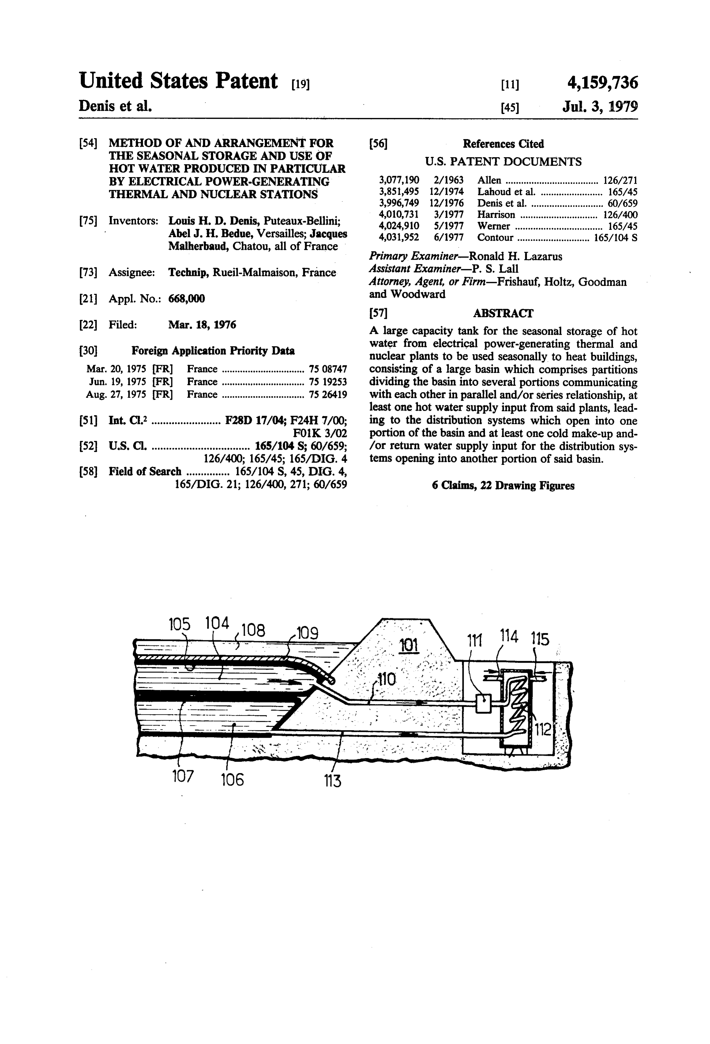
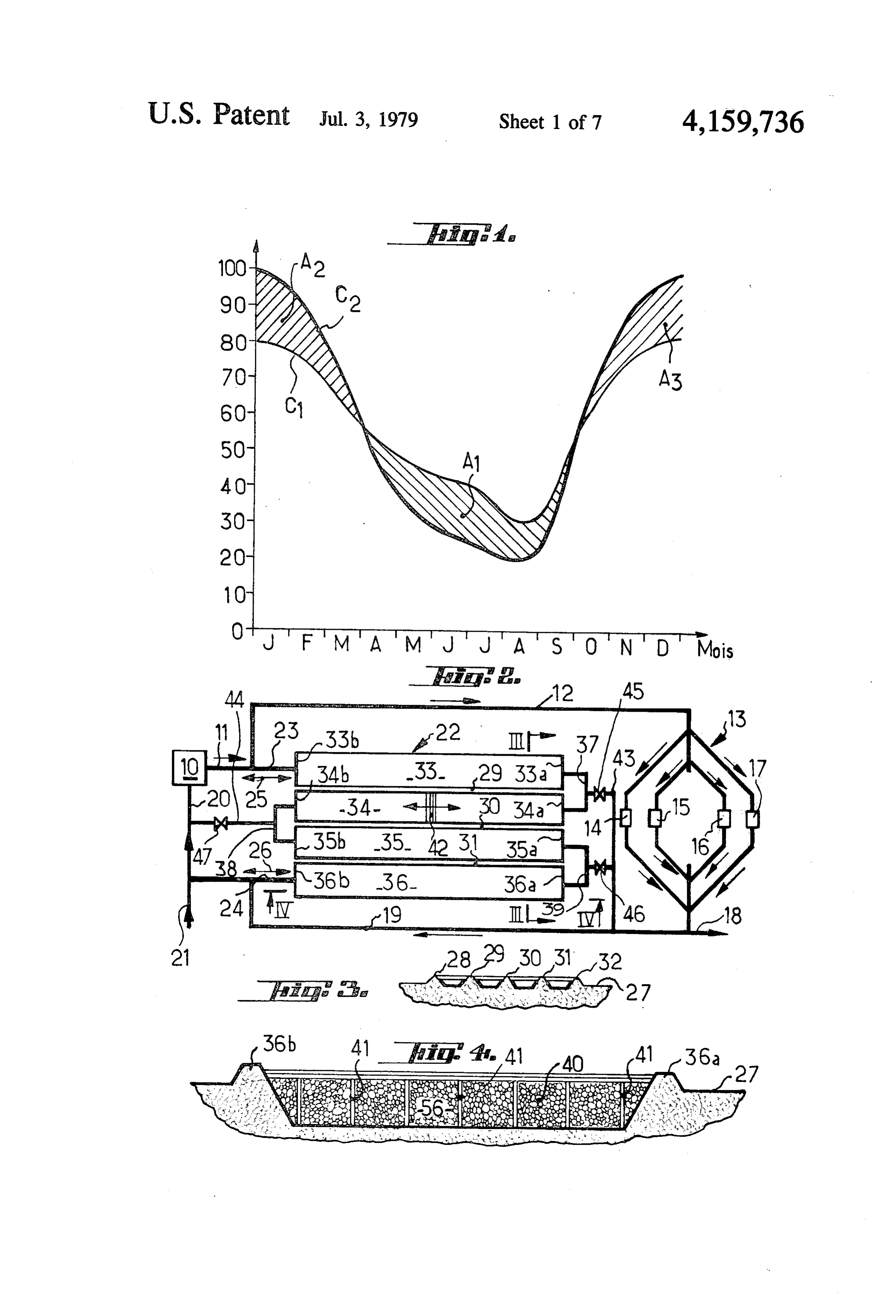
and even usually to supply additional heat energy, DETALED DESCRIPTION thereby adding to the seasonal storage of heat from the 30 hot waters produced by the power stations a seasonal FIG. 1 which illustrates the economically interesting storage of heat generated by the radiation from the sun. character of the invention will be referred to first. In BRIEF DESCRIPTION OF THE DRAWINGS this Figure the curve C1 gives the amount of heat weighted over several years, discharged as waste in
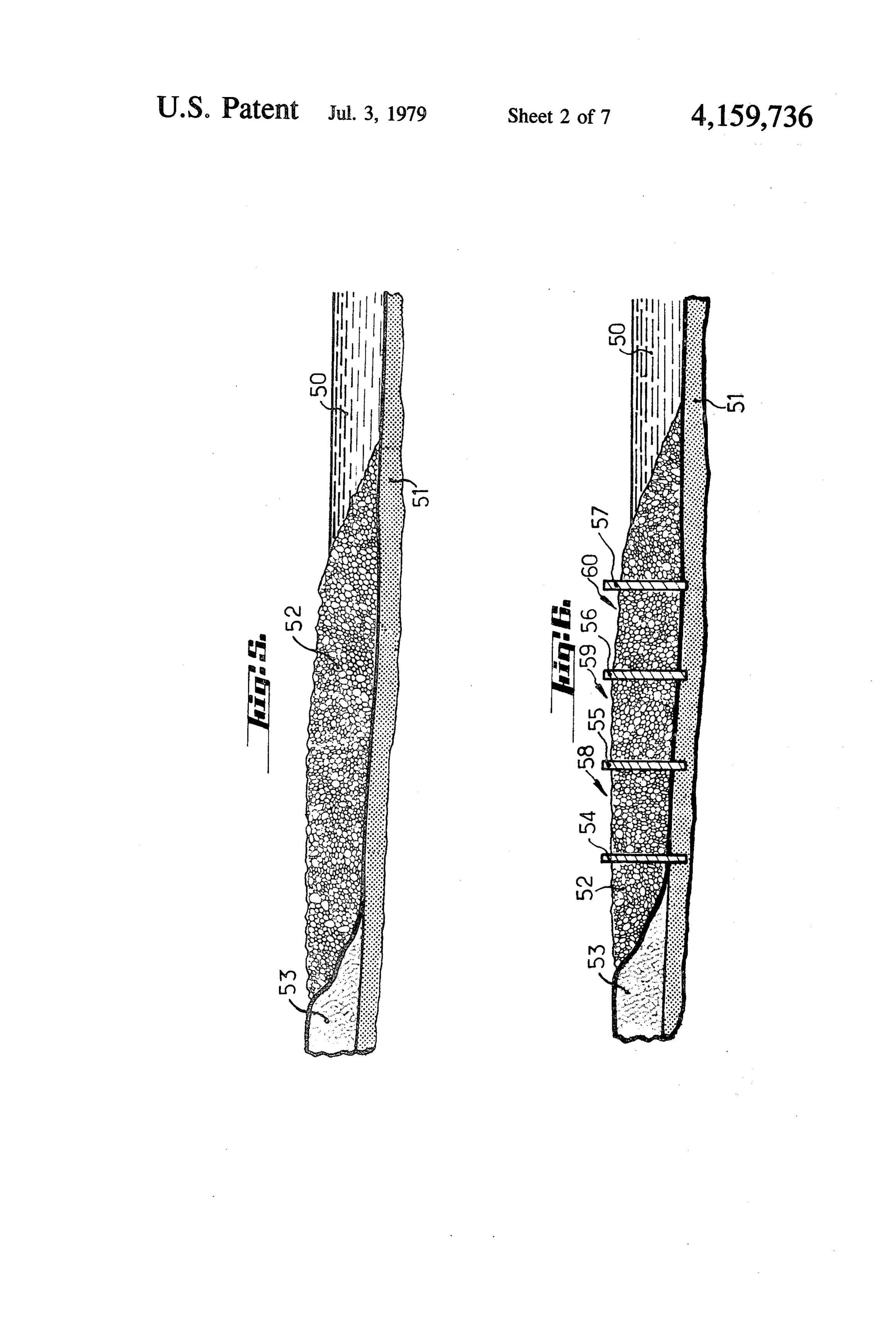
Other characterizing features, objects and advantages 35 France by the thermal and nuclear power stations into of the invention will appear more clearly as the follow the rivers or into the atmosphere (while taking into ing detailed explanatory description proceeds with ref. account the overall efficiency of electricity production erence to the accompanying diagrammatic drawings which is of about 30% to 35%), this amount of heat given by way of examples only and wherein: being plotted as the ordinate as a function of the time FIG. 1 is a graphical chart showing the seasonal period of the year plotted as the months in abscissa. correlation between the production of heat rejected by Likewise in this Figure the curve C2 gives the sea the thermal and nuclear power stations in France and sonal needs in heat more particularly for district heating the seasonal needs in heat in particular for district heat purposes.
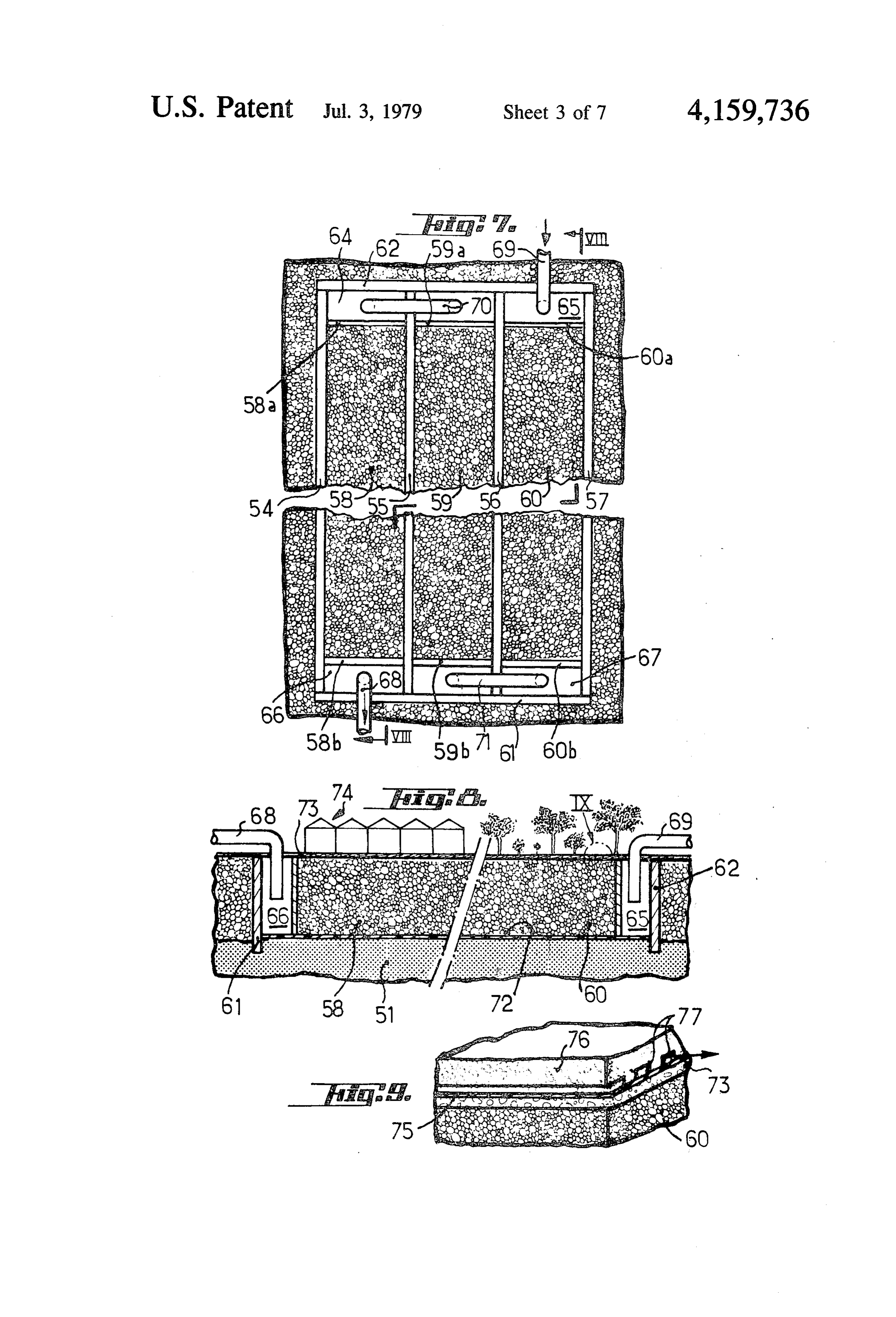
ing purposes; From a comparison of both curves it appears that the FIG. 2 is a diagrammatic view of the layout of a plant 45 production of waste heat by the power stations is higher designed according to the invention and enabling the than the heat required for the warm season (in particu seasonal storage and use of the excess heat produced by lar from April to August) and that it is lower than the a power-generating station; heat required for the cold season (in particular from FIG. 3 is a view in cross-section taken substantially November to February).
upon the plane III-III in FIG. 2 through the tank 50 Therefore when using the "total energy” process structure shown in FIG. 2 and designed according to advocated in the aforesaid U.S. patent application ac the invention; cording to which the heat generated by the power sta FIG. 4 is a longitudinal sectional view drawn on a tions and not converted into electrical power is used for larger scale through a tank structure of the kind illus heating dwelling premises and for various other indus trated in FIGS. 2 and 3; 55 trial applications (chemical industry, soap works or like FIG. 5 is a cross-sectional view diagrammatically factories, wash-houses, laundry-rooms and so on) it has showing a structure of grounds commonly encountered been found that during warm time periods the power along a river; stations supply an excess of energy which may not be FIG. 6 shows the structure of grounds as illustrated in used at that time whereas during the cold season they FIG. 5 which has been used to provide a storage tank do not generate enough power.
according to the invention; When comparing both curves C1, C2 it appears that FIG. 7 diagrammatically shows a top view of the the hatched or shadowed area A1 between the curves tank made as shown in FIG. 6; C1 and C2 which corresonds to the amount of excess FIG. 8 is a view in longitudinal section taken substan energy supplied by the power stations during the warm tially upon the plane VIII-VIII of FIG. 7; 65 seasons has a surface area substantially equivalent to the FIG. 9 is a view drawn on a larger scale of the encir added hatched or shadowed surface areas designated at cled detail IX of FIG. 8, showing the composition of the A2, A3 which show the additional energy requirements ground above the tank; in the form of heat during the cold seasons which may
Page 11
not be met by the power stations. It is moreover seen dams or weirs for the so-called "earth' dam type such that the surface area A1=A2+A3 is about 10% of the as in Serre-Poncon.
surface area defined between the curve C1 and the axis In this instance it is only necessary to dig trenches of abscissa, i.e. corresponds to 10% of the total energy into the ground which will form the portions 33, 34, 35, released as heat by the power stations. 5 36the waste or excavated material forming the raised or Thus by storing a part of the excess power released elevated walls of the channels 28, 29, etc.. The walls by the power stations during the warm seasons it is will be compacted, covered with fine inert material possible to decrease by more than 20% the maximum such as sand and sealed or made impervious in fluid power output of said power stations which would oth tight or leak-proof relationship with sheets or foils of erwise have been required to meet the demand (by 10 absorbing the power requirements corresponding to the plastic material welded or bonded to one another. The channels may be several hundreds of meters long and a areas A2, A3 and by decreasing the requirements from few tens of meters wide and deep. 100 points to less than 80 points). .. Upon performing the computations it appears that a The invention advocates a specific tank and plant few hundreds of hectares of tank surface area thus construction which enables such seasonal storage of 15 formed will be enough to allow the seasonal storage in large amounts of heat and a practical later re-use or France of any amounts of hot water released in excess recovery thereof while providing for a valorization of by the thermal and nuclear power stations during the the sites. warm seasons and the re-use of such a stored heat dur The form of embodiment shown in FIGS. 2 to 4 will now be referred to. ing the cold seasons.
Referring at first to FIG. 2 the reference numeral 10 outThe working of the plant shown in FIG. 2 is carried as follows.
designates a for instance thermal power station which serves the purpose of generating electricity and which hotThe thermal power station 10 discharges its excess rejects hot water at a temperature of for instance 70° C. 12 and thethrough water the pipe-line 11 towards the pipe-line utilization system 13. When the amounts of to 90° C. as a waste by-product. The hot water rejected 25 by the power station is discharged by a pipe-line 11. The hot water supplied by the power station are higher than the requirement of the users or consumers, the excess pipe-line 11 is feeding a pipe-line 12 leading to a utiliza tion system 13 diagrammatically shown at 14, 15, 16 and hot water is fed by the pipe-line 23 into the tank 22 at 17. At the outlets of the utilization appliances 14-17 the the inlet 33b of the channel 33. The hot water is flowing slowly and regularly forward within the channel 33 cooled water may be drained off in part at 18 for in 30 stance towards rivers and recycled at 19 towards the while driving back gradually ahead of it the interface or pipe-line 20 feeding cold water into the power station separation front with the cold water which has been 10. At 21 is shown a source of cold make-up water assumed to be located at 42. The hot water taken into required to compensate for the losses and wastes. the tank will heat up the pebbles and accordingly cool In order to enable a feedback control of the circuit 35 down while flowing forward, thereby considerably there is provided at 22 a large-capacity tank for the decreasing the actual speed of travel of the interface or seasonal storage of hot water in particular during sum separation front 42 between the cold water and the hot mer time and from which water may be drawn to meet water with respect to the speed of flow of the water the peak requirements in particular during winter time. within the tank. At the same time the hot water is fed At 23 is shown the connection between the pipe-line 11 into the tank through the pipe-line 23, the cold water is for the hot water issuing from the power station and the drawn from the tank through the pipe-line 24. tank 22 and at 24 is shown the junction of the tank 22 With a view to restrict the head or pressure losses with the cold water circuit 19, 21. The double arrows there may possibly be provided shorter return circuits 25, 26 show that there may be an addition or input of or paths for the cold water such as diagrammatically hot water into the tank 22 and a correlative drawing-off 45 shown at 43, 44 provided with valves 45,46, 47. Thus in or output of cold water or reversely a drawing-off or the embodiment shown in FIG. 2 when the interface or output of hot water and a correlative addition or input separation front between the hot water and the cold of cold water. water is located at 42, the valves 45, 46 may be closed As clearly apparent from FIGS. 2, 3 and 4, the tank and the valve 47 may be opened for allowing the return 22 is a tank with a large surface area provided substan 50 of cold water to take place directly between the end 34b tially on ground level 27 and comprising partition walls of the channel 34 and the return pipe-line 20 by-passing 28, 29, 30, 31, 32 which divide the basin into several the channels 35, 36.
water retaining portions 33, 34,35, 36 which communi When the requirements of the demand are higher cate with one another. In the example shown, the por than the flow rate supplied by the power station 10, hot tions 33-36 communicate with each other in series rela 55 water will be taken from or drawn off the tank 22 tionship through connections diagrammatically shown through the pipe-line 23, a corresponding cold water at 37, 38, 39 at their adjacent ends 33a, 34a; 34b, 35b; flow rate being injected at the other end of the tank or 35a, 36a, respectively. also for instance through the pipe-line 44 in the example According to a preferred embodiment of the inven shown. In a manner reverse to the heating up process of tion the hollow space of the basin is essentially filled as 60 the tank described hereinabove the cold water front 42 shown in FIG. 4 with a porous structure consisting of will advance much more slowly than the cold water gravel or pebbles 40. Moreover, porous or perforated flow rate injected into the tank while taking into ac partitions 41 are advantageously provided within each count the gradual cooling down of the pebbles. channel such as 33, 34, 35, 36 at intervals along the Thus with a relatively small bulk of stored water separating portions of the basin (FIG. 4). 65 which may be or not recycled wholly or in part, there The basin may be made according to any known is provided a seasonal storage of huge amounts of en suitable process and for instance according to a process ergy within the bodies or masses of the pebbles of the similar to the one which is used for providing hydraulic basin.
Page 12
According to another advantageous characterizing If desired and as illustrated in FIG. 8 the bottom of feature of the invention and as will become apparent the tank may be provided with an insulating layer 72 more clearly in the following description of another consisting for instance of injected plastic foam which embodiment shown in FIGS. 5 to 9, the porous struc will limit the heat losses towards the adjacent grounds. ture is covered or lined over the surface thereof with an The surface of the basin should advantageously be impervious or sealing layer such as a concrete or asphalt covered with a fluid-tight layer for instance of concrete layer possibly covered with a heat-insulating material. or asphalt 73 which will limit the evaporation and heat This surface which remains tempered in any season is losses and onto which may be arranged glasshouses 74 suitable to receive playgrounds or like playing areas, for the forcing of plants such as fresh or early vegeta concert halls, glasshouse cultivations, etc. O bles, exotic trees (oranges, etc.). Cultivation in the open Although in FIGS. 2 to 4 there has been depicted a air or out of doors may also be contemplated. rectangular basin structure divided into several longitu On ground level there should advantageously be dinal juxtaposed channels it is obvious that other shapes arranged as shown on a larger scale in FIG. 9 over the of basins in particular adapted to local conditions may pebbles 60 a concrete or asphalt layer 73 and then a be selected such as for instance circular, elliptic, spiral 15 layer of a suitable heat-insulating material 75 (glass and other shapes. In any case one should advanta wool, plastic foam, etc.). If cultivations are contem geously contrive to divide the basin into several elon plated, a layer of tillable soil or tilth 76 should be ar gated separation zones which may communicate with ranged above the layers 73, 75 and should advanta each other in parallel and/or in series connected rela geously be formed with ventilation ducts 77 in particu tionship to enable a good programmed working of the 20 lar for the hot summer-time periods. whole surface of the basin. Many modifications may of course be brought about Reference is now made FIGS. 5 to 9 wherein a partic to the forms of embodiment and working examples ularly advantageous process of the making a tank ac described which have been given by way of illustration cording to the invention has been illustrated. only.
In FIG. 5 is diagrammatically shown a sectional view 25 Thus in particular in the case where the surfaces of of a rather conventional formation which may be en the grounds occupied by the hot water storage is cov countered at different geographical places and in which ered with cultivations, in particular in glasshouses, the there may be found along a river 50 a bed of gravel 52 basin will advantageously be divided into several zones resting on an impervious layer of marl or clay 51 and in which the hot water and cold water will be cyclicly which often is several meters thick, a few hundreds of 30 drawn therefrom and fed thereto according to the re meters wide and several kilometers long. At 53 may be quirements or needs of the demand while however seen one edge, brink or verge of the valley consisting of taking into account the cyclic cultivations carried out at any kinds of grounds. the surface within said zones. In such a formation there are provided according to Moreover in a manner reverse to what has been de the invention as seen in FIG. 6 fluid-tight walls 54, 55, 35 scribed it is possible to store in the tank during winter 56, 57 made for instance from concrete and which ex time cold water, i.e. that which is injected at the same tend through the thickness of the porous structures of time the hot water is drawn off and to use the cold the pebbles 52, said walls defining between one another water during summer time as a coolant for condensers, channels or separation zones 58, 59, 60. The concrete refrigerating machinery, heat engines, air-conditioning partition walls 54, 55, 56, 57 may be built according to of rooms and premises, etc. Storages at temperatures any suitable process for instance through continuous lower than 0° C. may possibly be carried out by using casting with a travelling shuttering or formwork mov instead of water other suitable solutions such as brines, ing behind a ripper blade or the like which opens the etc.
bed of pebbles down to the marl layer 51. In such a According to the embodiment diagrammatically manner as diagrammatically shown in top view in FIG. 45 shown in FIG. 10 there is seen a cross-sectional view of 7, there is provided a tank of a general type similar to a basin 100 which is dug out or excavated like a trench that illustrated in FIGS. 2 to 4, comprising channels 58, within grounds 101, the waste or excavated materials 59, 60 limited by channels 54 to 57 and closed at their serving the purpose of forming retaining side dikes or ends by walls 61, 62. embankments 102, 103. Such a basin may of course be Towards each end of the channels there are advanta 50 given any desired length so as to match the amounts of geously provided porous partitions 58a, 59a, 60a; 58b, water which are desired to be stored and several basins 59b, 60b which will retain the pebbles and leave at each of this kind may be connected in parallel and/or in end of the channels spaces 64, 65, 66, 67 in which are series relationship while being laid out according to arranged ducts for interconnecting the channels and/or favorable local conditions.
drawing off and adding hot water and cold water. 55 In this basin has been enclosed the bulk of hot water In the tank shown in FIG. 7 the pipe-lines 68, 69 storage 104 inside of a pocket the membrane 105 of respectively perform the function for instance of the which is displaceable and deformable and for instance pipe-lines 23, 26, the inputs and outputs of hot water made from a sheet of plastic material such as polyvinyl, taking place at 68 and the inputs and outputs of cold polyethylene, etc.
water taking place at 69. Likewise the bulk of cold water storage 106 has been The junctions 70, 71 correspond to the junctions 37, enclosed within a pocket the membrane 107 of which 38, 39 in FIG. 2. may be made in a way similar to that of membrane 105. It is obvious that more than three channels may and It is advantageous as shown that the bulk of hot water will usually been used and various junctions (not storage 104 be positioned above the bulk of cold water shown) will enable the working or operation in parallel 65 storage 106 so that the lighter hot water will naturally and/or in series connected relationship according to the top or overlie the heavier cold water. requirements and to the local layouts of the various According to a particularly advantageous character separation zones of the tank. izing feature of the invention both bulks or bodies of
Page 13
storage water 104, 106 are topped by a body of water 130 to the brinks or edges of the basin 100. The anchor 108 which will usually be open to the atmosphere and ing may be made at discrete spots or along edge lines. which thus forms a water surface or artificial lake. In The cold storage water 106 is stored below the roof order to limit the heat exchanges between the hot 125 and outside of the body 104. Thereabove is pro pocket 104 and the body of water 108 there should vided the water surface 108. According to the operating advantageously be provided above the bodies of storage requirements the pocket 104 will become deformed. water an insulating roof 109 made for instance of a There has thus been shown at 126 another position of plastic foam. the membrane 126 in which the tank contains less hot According to an original and interesting characteriz storage water and more cold storage water. ing feature of the invention, in order to provide for a 10 In FIG. 14 there has been shown another alternative normal stratification or arrangement into overlying embodiment wherein the body of hot storage water 104 layers of the stored waters, waters with specific gravi is enclosed within a pocket defined by a membrane 130 ties or densities and/or saltnesses higher than those of which is protected at the upper part by an insulating the water 108 should be used as storage waters 104,106. roof 131 which is resting thereon. The body 106 of cold For instance soft water may be used to provide the 15 storage water surrounds the pocket 104 which will water surface 108 and salt water for instance sea water automatically float at the top portion owing to the spe or a water loaded with potassium salts, baryum oxide, cific gravity of the hot storage water which is lighter etc. may be used as the storage water 104, 106. For than the cold storage water. Above the roof 131 is pro instance it will thus be found above at 108 soft water at vided again the water surface 108. In order to provide about 10 C. to 30' C. with a specific gravity of from 1 20 for a good separation between the bodies 106, 108 and to 0.996 and for the body 104 hot saltwater for instance allow the motions of expansion of the roof 131 the fluid sea water having at 90° C. a specific gravity of about tightness of the roof 131 and of its connection with the 1.010 and underneath the same salt water having at edges or brinks of the basin is achieved by means of a about 30° C. to 50° C. a specific gravity of 1.013. flexible membrane or diaphragm 132 properly anchored As shown in FIG. 11 such a basin is operated as foll 25 at 133 above the level of the water surface 108, which lows. membrane-like sheet 132 is connected to the roof 131. A When an outside heat requirement occurs, for in springing or overhanging portion 134 made for instance stance to heat buildings, hot water from the storage from concrete protects the relatively fragile flexible body 104 is pumped through a pipe-line 110 and a pump sheet 132 against external actions which are likely to 111 through a heat exchanger 112, the back flow or 30 tear or rip it open.
return of cold storage water being effected through the At 135,136 are seen the storage working ducts which return duct 113 into the body of cold storage water 106. perform functions similar to those of the ducts 110, 113 At 114, 115 has been diagrammatically shown the input in FIG. 11.
or return 114 of the cold water of the system and at 115 According to th alternative embodiment shown in is shown the output of the hot water towards the distri 35 FIG. 15 the body of hot storage water 104 is divided bution and utilization system (central heating of build into several adjacent bodies 104", 104", 104", 104" ings in particular). which are each one enclosed within a hose-like mem It is thus found that as the bulk of the body of stored brane 140, 141, 142, 143 which may extend the whole hot water 104 decreases, the bulk of the body of stored length of the basin. The pockets 104", 104", etc. are cold water 106 will increase accordingly, the storage surrounded by the lower body portion 106 of the basin tank operating at a substantially constant capacity or reserved for cold water storage purposes and are float volume except for losses and variations in expansion. ing at the surface of said body. In the example shown An exchanger of the same kind as the exchanger 112 the space 106 is made fluid-tight by means of a flexible may of course be used by reversing the direction of flow membrane 144. Above the storage waters is advanta through the pump 111 so that when the heat production 45 geously provided a protecting insulating roof 145 which of the power stations is higher than the requirements or forms the bottom of the artificial lake filled with the needs the heat of the waste hot waters discharged by the upper body of water 108.
power stations may be used for heating the cold storage In the case where the lake is adapted to serve for waters 106 and convey or feed them in the re-heated instance for aquatic sports it will be advantageous to condition into the storage body 104. 50 provide a protecting roof 145 strong enough to remove According to the alternative embodiment shown in any danger of damaging the lower portion of the basin FIG. 12 the body of cold storage water 106 is enclosed holding the storage waters. For this purpose and as between two yielding or flexible, deformable and mov shown in FIG. 16 the roof 145 may be made from a able membranes or diaphragms 120, 121 which are con sealing sheet 146 which may be fitted to cover the sheet nected as by bonding or welding and anchored with 55 144 of the body 106 and on which sheet 146 will be their edges 122, 123 to a flexible insulating roof 124. The arranged blocks of protecting material for instance cel body of hot storage water 104 is enclosed between the lular concrete blocks 147. In order to bear the weight of membrane 121 and the roof 124. Above the roof 124 the roof the lower storage space of the basin may be there is again the body of water 108 forming the water subjected as shown in FIG. 15 to a slight water over surface. Except for a difference in construction, the pressure by connecting for instance the space 106 arrangement shown in FIG. 12 may operate like that through a duct 148 to a small supply container 149 in shown in FIGS. 10 and 11. which will be kept a given water level 160 located at the According to the alternative embodiment shown in desired heighth above the water surface 150 of the lake. FIG. 13, the body 104 of hot water storage is this time This slight overpressure will enable to very readily enclosed between an insulating roof 125 comprising for 65 sustain the weight of the roof whatever its nature might instance an impervious layer of plastic foam and a flexi be.
ble deformable membrane 126 forming bellows on the According to the alternative embodiment shown in sides and properly anchored as shown at 127, 128, 129, FIG. 17 there are again three overlying bodies of water
Page 14
namely of cold storage water 106, of hot storage water water 104. However with such a construction of the 104 and of the water of the lake 108 together with a tank roof and without any additional expense the over protecting roof 151 which may for instance be of a all efficiency of the plant is improved. By way of exam construction similar to that of the roof 145. In this in ple the sheet 201 may have a thickness of about one stance as in FIG. 15 a slight overpressure h should be millimeter whereas the layer 202 may have a thickness provided in order to bear the weight of the protecting of about 25 mm and the sheet 203 may have a thickness roof 151. of about 2 mm.
The body 104 of hot water and the body 106 of cold According to the alternative embodiment shown in water may be separated from each other by a flexible FIG. 20 for constituting the roof 124 use is made of a deformable and/or movable membrane 152 which may O composite membrane comprised of a sandwich con be connected from place to place by means of rigging struction composed of the films 201 and 203 for example lines or ropes 153 to the roof 151. The operation of the identical with those shown in FIG. 19 which enclose tanks may of course be performed in the same manner in therebetween a gas or fluid 205 which plays the part of the forms of embodiment which have just been de the layer 202. Spacers or like bracing members such as scribed and in the one which has been discussed when 15 rods or threads 206 properly secured to the sheets 201, depicting FIGS. 10 and 11 for instance. 203 provide for the proper spacing left between these According to the embodiment shown in FIG. 18 two sheets.
there is shown again a structure which has already been The nature of the gas or fluid 205 used is selected so described with reference to FIG. 12. There is thus seen as to be consistent with a good preservation of the a membrane 124 which forms the roof covering the sheets 201 and 203 and also so as to promote the trans body 104 of hot storage water enclosed between the mission of heat power in the form of light from the membrane 121 and the roof 124. Underneath the body outside towards the tank and to reduce the flow in the of hot storage water 104 there is provided the cold reverse direction or outwards from the tank towards storage water 106 enclosed between the membrane 121 the outside of the heat through radiation and conduc and a membrane 120, the storage comprising more or 25 tion.
less bulky relative bodies of hot water 104 and of cold Alternatively there may be used as a fluid 205 for water 106 according to the season. Above the roof 124 instance water which may form a buffer layers at an is formed a water surface 108 enclosed in a sink or intermediate temperature between that of the hot water trough of ground 101. layer 104 and that of the upper cold water layer 108 The improvements relating to the construction of the 30 reducing the outward directed heat emissions from the "roof which will now be described are very well appli tank towards the outside. This hot water layer 205 may cable to this kind of tank but also to other embodiments possibly be introduced into the storage space or mixed of the tank described with reference to the other Fig with the storage water while adjusting the supply and CS. mixing flow rates according to the temperature reached Reference will now be had to FIG, 19 illustrating the 35 by the layer 205 in accordance with the actual outside manner of making the roof in accordance with these conditions prevailing at that time. The pressure of the improvements. fluid or gas 205 will of course be kept at the desired According to the embodiment shown herein the value to provide the proper spacing between the sheets membrane of the roof 124 is of a sandwich construction 201 and 203. The gas may for instance be air or nitrogen of three layers, namely a top layer 201 which lets the introduced under a suitable pressure for instance lower major part of the light flux pass therethrough, a trans than atmospheric pressure so as to improve the insula parent layer 202 with a low coefficient of heat conduc tion of the composite membrane. In such a case in par tivity and a layer 203 which absorbs the major part of ticular the lower layer 203 and/or the upper layer 201 the light radiation received. may be made so as to be formed with a bright bottom For instance the layer 201 may consist of a transpar 45 surface 203a, 201a in order to take advantage of the ent sheet of plastic material such as transparent butyl DEWAR effect.
rubber or any suitable synthetic material such as for According to the alternative embodiment shown in instance a polyester film, a polyethylene terephthalate FIG. 21 the sheets 201 and 203 enclose therebetween a resin such as known under the registered trademark layer 207 comprised of a cellular plastic foam with “MYLAR R' or the like. The layer 202 may consist of SO oriented cells having their major size surfaces extending a transparent synthetic foam having a low thermal con substantially horizontally. This foam should be selected ductivity. The layer 203 may consist for instance of a so as preferably to be transparent or in particular trans butyl rubber with a carbon black filler. lucent so that the outer light radiation may travel easily The light flux, such as for instance solar radiation therethrough whereas the orientation of the cells will diagrammatically designated by the arrow 204, after 55 reduce the outward directed heat emission through having passed through the top water layer 108 travels radiation and conduction from the storage space through the transparent film 201 and then through the towards the outside.
transparent layer 202 and is eventually absorbed by the According to the embodiment shown in FIG. 22 the absorbing layer 203. The infra-red radiation re-emitted roof 124 separating the cold water 108 from the hot by the layer 203 is reflected by the layers 202 and 201 water 104 essentially comprises a layer 208 absorbing back towards the hot storage water 104 so that the heat the outer light radiation, made of for instance a layer of supply from solar radiation generally enables to com heavy hydrocarbon. This hydrocarbon layer may be pensate to a large extent for the heat losses of the hot arranged upon a fluid-tight film 209 for instance in a storage water towards the outside. The efficiency is of manner similar to that which has been described previ course not perfect since some part of the sun radiation 65 ously in particular with reference to the description of 204 is reflected back by the water layer 108 and also by FIGS. 15 and 16.
the layers 201 and 202. Moreover all the heat absorbed By selecting the layer 208 to be thick enough it will at the layer 203 is not used for heating the hot storage both perform a function of mechanical protection of the
Page 15
tank roof and a function of storing solar heat capable of means coupled to said first and second means for compensating for at least a major part the outward controlling the flows of water such that an instanta directed heat losses from the storage space towards the neous supply of hot water into said upper storage outside. Moreover the layer 208 will promote a certain pocket is balanced by a corresponding drawing off temperature increase of the cold water 108 which may of cold water into said bottom storage pocket, and be favorable for fish-breeding or for building swimming such that an instantaneous drawing off of hot water pools. into said upper storage pocket is balanced by a The application procedures which have been de corresponding supply of cold water into said bot scribed of the improvements to the construction of the tom storage pocket, said bottom and upper storage roof may of course be applied to most of the described 10 pockets providing together a substantially constant embodiments of the invention. The essential idea resides volume body of storage water. in providing the roof of the storage space so as to pro 2. A tank according to claim 1 further comprising mote the conveyance of outer heat due to solar radia duct means coupled to said upper hot water storage tion towards the hot water storage and to reduce the pocket and to said bottom cold water storage pocket; conveyance of heat from the storage space towards the 15 and a heat exchanger coupled to said duct means for outside. supplying heat to the water flowing in said duct means What is claimed is: when circulation of water occurs from the bottom cold 1. A large-capacity tank for seasonal storage of hot water storage pocket to the upper hot water storage water, produced for example by electric power pocket, and for taking off heat from the water flowing generating thermal and nuclear stations, and for their 20 in said duct means when circulation of water occurs seasonal use, for example for the heating of buildings, from the upper hot water storage pocket to the bottom comprising: cold water storage pocket.
a water containing basin of large surface area; 3. A tank according to claim 1 wherein at least one of two superposed individual inflatable pockets con said pockets comprises a bladder anchored to the walls tained in said basin, the bottom pocket being for 25 of said basin.
storage of cold water, and the upper pocket being 4. A tank according to claim 1 wherein each one of for storage of hot water at a temperature near 90 the pockets comprises a sealed closed volume the wall C., both of said pockets lying under water con of which is made of an impervious deformable plastic
at least one of said pockets having an impervious 30 5. A tank according to claim 1, wherein the upper plastic sheet deformable wall located between the storage pocket is provided with an insulating roof contents of said upper and bottom storage pockets; above which is formed a water surface or lake, the first means coupled to said bottom storage pocket for bottom of which is constituted by said roof. supplying and recovering cold water stored in said 6. A tank according to claim 5, wherein the volume of bottom storage pocket; 35 said lake or water surface comprises a water having a second means coupled to said upper storage pocket specific gravity and/or saltness lower than those of said for supplying and recovering hot water stored in stored hot waters and cold waters.
said upper storage pocket; and s
Provenance
- Collection
- Cited prior art
- Original PDF
- patentimages.storage.googleapis.com →
- Filed
- 1976-03-18
- Pages
- 15
- Method
- pdftotext (the PDF's own text layer) + pdftoppm 300dpi page scans
- Source
- Google Patents bibliographic record
- Granted
- 1979-07-03
- Inventors
- Louis H. D. Denis; Abel J. H. Bedue; Jacques Malherbaud; Technip SA
- Transcribed from
- patentimages.storage.googleapis.com →