patent · US3851495
Method and apparatus for preventing thermal pollution
3 December 1974
Page 1 — bibliographic record
United States Patent (19)
Lahoud et al.
(54) METHOD AND APPARATUSFOR OTHER PUBLICATIONS
PREVENTING THERMAL POLLUTION
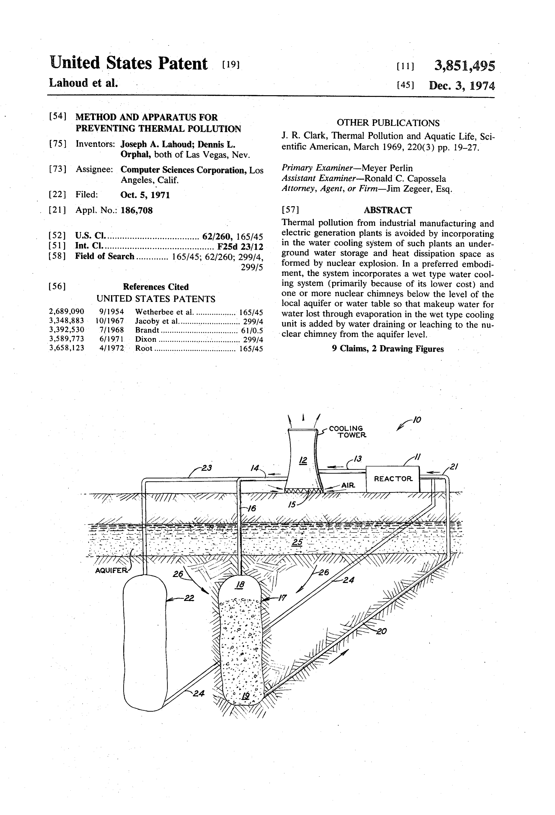
75) Inventors: Joseph A. Lahoud; Dennis L. J. R. Clark, Thermal Pollution and Aquatic Life, Sci Orphal, both of Las Vegas, Nev. entific American, March 1969, 220(3) pp. 19-27. 73) Assignee: Computer Sciences Corporation, Los Primary Examiner-Meyer Perlin Angeles, Calif. Assistant Examiner-Ronald C. Capossela 22 Filed: Oct. 5, 1971 Attorney, Agent, or Firm-Jim Zegeer, Esq. (21) Appl. No.: 186,708 (57) ABSTRACT Thermal pollution from industrial manufacturing and 52) U.S. Cl...................................... 62/260, 165/45 electric generation plants is avoided by incorporating 51) int. Cl............................................. F25d 23/12 in the water cooling system of such plants an under 58) Field of Search............. 165/45; 62/260; 299/4, ground water storage and heat dissipation space as 299/5 formed by nuclear explosion. In a preferred embodi ment, the system incorporates a wet type water cool 56) References Cited ing system (primarily because of its lower cost) and UNITED STATES PATENTS One or more nuclear chimneys below the level of the local aquifer or water table so that makeup water for 2,689,090 9/1954 Wetherbee et al............ 165/45 water lost through evaporation in the wet type cooling 3,348,883 - 10/1967 Jacoby et al........... ...... 299/4 unit is added by water draining or leaching to the nu. 3,392,530 7/1968 Brandt................................... 6110.5 clear chimney from the aquifer level. 3,589,773 6/971. Dixon..................................... 299/4 3,658,123 4/1972. Root "VV www a a do see s A a . . . . . . . . . . . . . 165/45 9 Claims, 2 Drawing Figures
TOWER
Page 2
Drawing sheet — no readable text.
Page 3
Drawing sheet — no readable text.
Page 4
METHOD AND APPARATUS FOR PREVENTING bodiment of the present invention, waste heat from a THERMAL POLLUTION nuclear electric power plant or other industrial facility is, at least, partially dissipated in the earth by using the
The present invention is directed to the use of an un chimney formed by an underground nuclear explosion derground water storage reservoir as a part of a water as a large discharge water well and storage reservoir for circulation system for industrial facilities such as to dissipating heat into the earth interior and as a part of prevent thermal pollution of natural water. a substantially closed circuit cooling water system. In The subject of thermal pollution of natural waters has the accompanying drawings, such a system is disclosed been receiving increasing attention as evidenced by the as applied to a nuclear electric power generating sta establishment of provisional thermal pollution guide 10 tion or facility.
lines by the Federal Water Pollution Control Adminis One or more underground nuclear explosions can be tration of the Department of the Interior and hearings detonated before plant construction (so that seismic conducted by the U.S. Senate Air and Water Pollution data can be developed for and in design of the facility). sub-committee. The extent of the problem as well as a Such devices can be detonated in such a way that the number of prior art solution is shown in the following 15 chimney would be formed below the local water table articles: or aquifer. Water used to cool the nuclear reactor is 1. "Thermal Pollution and Aquatic Life" by John R. passed through a cooling unit and then discharged into Clark appearing in Scientific American magazine the chimney region at the top portion thereof, and the March 1969, Volume 220, No. 3, pp. 19-27; cooler water removed from the bottom portion for 2. "Power Plants and Heat Pollution" by Richard H. 20 reuse as described in detail hereinafter. Thus, using Gulley, Science News magazine, Aug. 1, 1970, Vol. 98, such a technique, a portion of the waste heat from the No. 5, pp. 89-104; reactor would be slowly dissipated at a great depth in 3. "Burgeoning Atomic Plants Run Into Pollution the earth and substantially all the water is reused and Awareness" by Thomas O'Toole appearing in the not discharged into the natural waters thus, the inven Washington Post newspaper, Tuesday, Aug. 25, 1970. 25 tion, in its preferred form, uses a nuclear explosion technology to aid in control of thermal pollution.
As shown in these articles, the concern for thermal Thus this invention permits relatively extensive flexi pollution arises from the estimate by the year 2,000 bility in the location of excess heat generating facilities. electric power production in the United States will Siting is not dependent on streamflow or on proximity reach about 2 million megawatts; about 1.2 million of 30 of large bodies of water. Underground sources or sur which will be produced by nuclear power. This esti face runoff in many geographical settings will be ade mated electrical power production will require the dis quate for initial charging and periodic recharging of the sipation of about 20 million BTU's of waste heat per nuclear explosion created underground reservoir. day. To dissipate this waste heat through the flow of The above and other objects, advantages and fea natural waters would require approximately one-third 35 tures of the invention will become apparent from the of the average daily freshwater runoff in the United following description taken with the accompanying States. The potential ecological hazard to aquatic life drawings wherein:
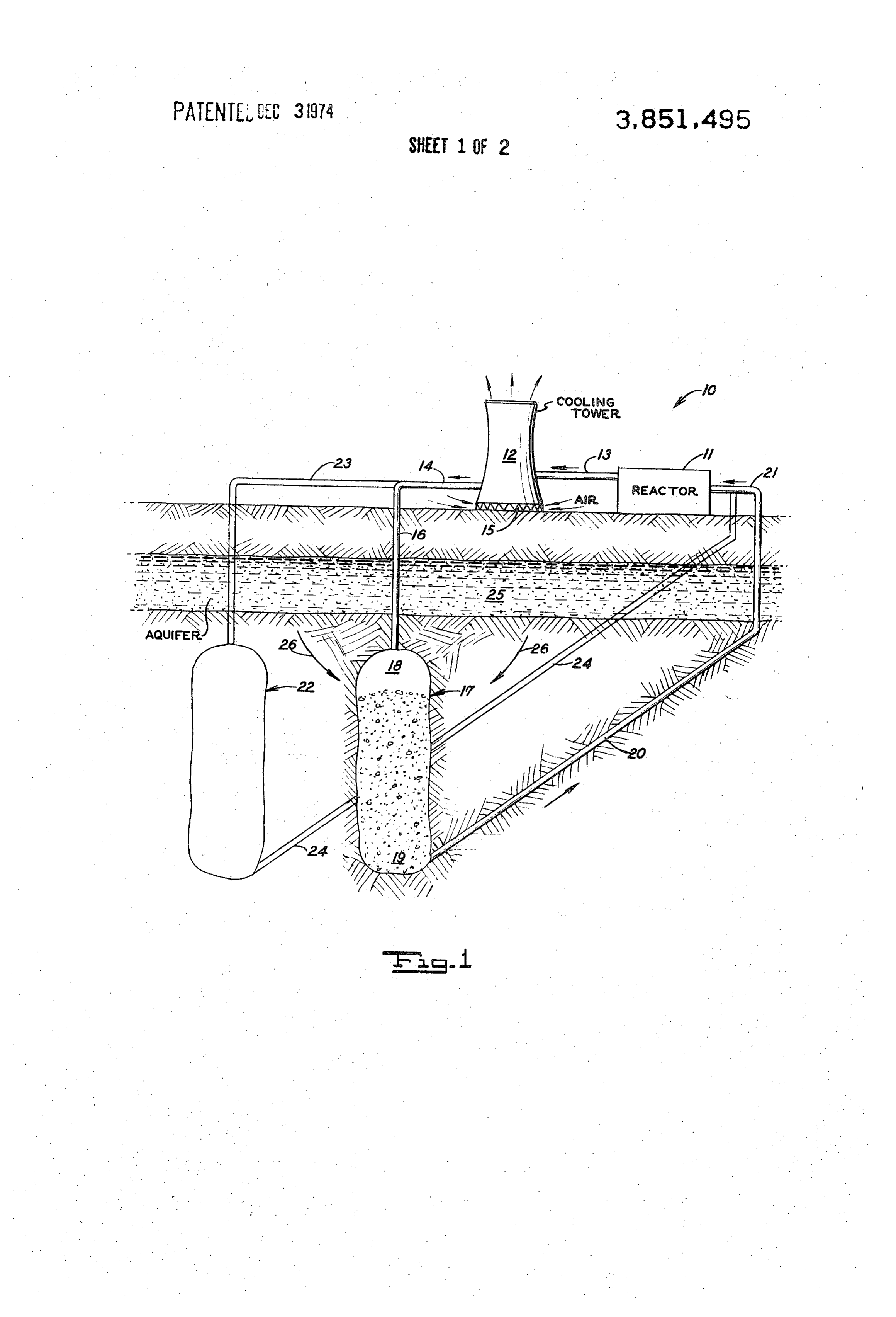
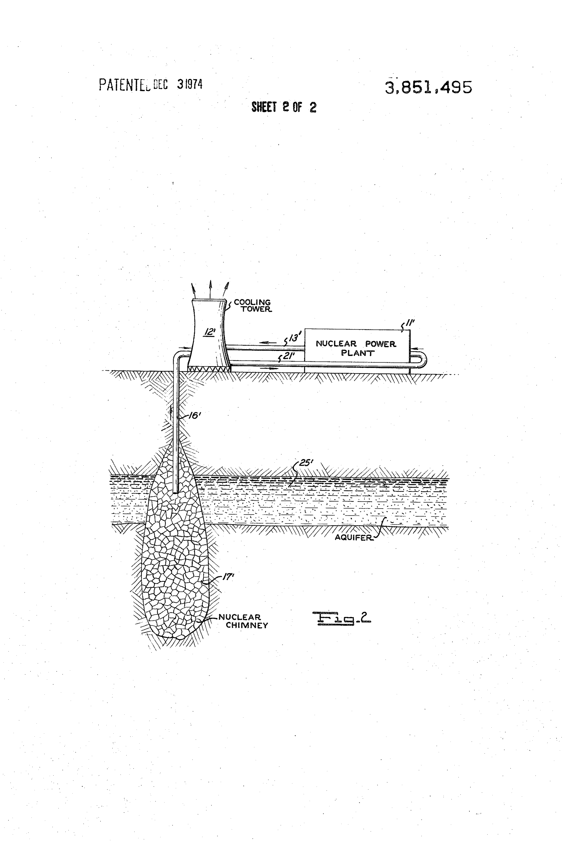
from dissipation of this waste heat through natural FIG. 1 is an embodiment of the invention as applied water fow is described in detail in the article from to a closed or substantially closed circuit cooling sys "Scientic American' (i) above. 40 tem and,
Recognizing the present and potential ecological FIG. 2 illustrates a modification of the invention. problems of thermal pollution, Federal legislation in Referring now to FIG. 1 of the drawing, the system the United States has been proposed which would re is shown as applied to a nuclear electric power generat quire thermal pollution control features to be incorpo 45 ing station 10 having a reactor 11 through which cool rated into the design of any proposed nuclear power ing water is caused to flow. Cooling water from reactor plant before licensing for construction could be ob 11 is conveyed in a conventional manner to cooling tained. tower 12 by way of a pipe system 13. Cool water from The above referenced articles disclose many tech cooling tower 12 is discharged through pipe 14 to the niques have been proposed for safely dissipating the 50 underground storage reservoir system. Cooling air for waste heat from a nuclear power plant or other indus the cooling tower enters the lower end of the cooling trial facility. Some of these techniques are discussed in tower at 15 in a conventional manner and exits through detail in the above articles, particularly the articles the top, such cooling towers are typically of two broad from "Scientific American,' and "Science News' in categories namely the wet type and the dry type. A de cluding regulating the discharges into the natural wa 55 tailed disclosure of these types of cooling towers is ters, use of artificial lakes and use of cooling towers. All found in the above-identified Scientific American arti of these techniques have serious economical and/or en cle. Water discharged from the cooling tower 12 may vironmental drawbacks. For instance, to dissipate the be several degrees above the natural temperature of the waste heat from a 1,000 megawatt nuclear power plant natural water. Such an elevated temperature of water by use of an artificial lake would require a lake with a cannot be discharged directly into the local natural wa surface area of 1,000 2,000 acres with a depth up to 50 60 ters because of the problem of thermally polluting such feet. In many areas, such a tract of land would be pro waters and changing the ecological condition thereof. hibitively expensive. Accordingly, such water is caused to flow into a nu Underground reservoirs (natural and man-made in clear chimney or storage reservoir 17 by means of a cluding nuclear) have, obviously, been used in the past pipe system 16. It will be noted that the water is intro for gas as well as water storage. (For example, water 65 duced at the upper level 18 of nuclear chimney 17. storage purposes and/or management purposes, see Cooler water as it gravitates through the rubble, and U.S. Pat. No. 3,589,773.) In accordance with one em rocks and fissures in nuclear well or chimney 17 is
Page 5
tapped or removed from the lower level 19 thereof by the chimneys are located to receive and dissipate heat means of a pipe system 20 which leads to the surface from the water.
of the earth. Such cooled water is therefore recircu The concept of a contained underground nuclear lated through reactor 11 by means of pipe system 21. detonation to create a reservoir for the purpose of uti Thus, a substantially closed cycle system for cooling lizing groundwater as a nuclear power plant coolant is water is shown in this embodiment. also disclosed in the embodiment shown in FIG. 2. In As described above, cooling tower 12 is typically of this case the detonation creates a large, highly permea two types (see the Scientific American article). The ble chimney 17' intersecting an aquifer 25". The chim first designated generally as a dry type provides for ney functions as a large-diameter groundwater well and miles and miles of copper tubing through which the 10 water is delivered therefrom by pipe means 16'. The heated water is caused to flow. Cooling air enters groundwater replaces the water lost through evapora (forced or by convection currents) at 15 in the bottom tion in a cooling tower 12" which dissipates the plant's of such tower and exits from the top as shown. Cooled waste heat. Heated water is delivered to cooling unit water from tower 12 is delivered to pipe 14 and enters 12' by pipe means 13' and cooled water including the storage and cooling system constituted by nuclear 15 makeup water from chimney 17' is delivered to the re chimney 17. Since dry type cooling towers do not use actor by pipe 21.
or lose much water such dry types can be used where Appropriate explosive design and shielding would en there is no immediately available underground water sure a minimum initial level of radioactivity in the table or use for one. In other words, where the water chimney. Any radioactivity entering the aquifer would table or aquifer is not available or is of very low water 20 be quickly diluted.
yield and insufficient to supply the needed makeup A specific example of a 200 kiloton nuclear detona water the dry type tower is preferred. However, in a tion in tuff at a depth of 2,000 feet will now be de most preferred form of the invention, the cooling tower scribed. Such a detonation creates a chimney with a ra 12 is of the "wet" type which means that it is signifi dius of about 290 feet and a height of about 1,500 feet. cantly less expensive than the 'dry' type. Moreover, in 25 Assuming a typical aquifer for the Western United order to make up for lost water due to evaporation of States with a coefficient of permeability of 10 gal/day water in cooling tower 12, the storage and cooling nu ft, a saturated thickness of 100 feet and an effective clear chimney 17 is located below the aquifer 25 so that hydrostatic head of 100 feet, the rate of water flow into water flows from the aquifer to chimney 17. This avoids 30 the chimney is calculated to be 1.5 x 10 gal/min. As heated water being carried to a possibly nearby stream suming a 1,000 MWe reactor with a cooling water cir by the flowing water in the aquifer. culation rate of 7 x 10 gal/min and 3 percent evapora Typically, the diameter of the chimney 17 may be tion loss in the cooling tower, the calculated rate of 250 to 500 feet and 1,500 to 2,500 feet in height. water flow into the chimney is sufficient to ensure a Moreover, when a nuclear explosion is used to form 35 steady-state condition.
the chimney 17, observance of Nuclear Test Ban The cost of a commercial nuclear detonation is antic Treaty Safety Rules, of course, is mandatory so the det ipated to be about $1 million. The corresponding cost onation is set off at approximately 3,500 feet below the of the water storage capacity created by a 200 kiloton earth surface and such charge is typically less than a detonation is about $500 per acre-foot, comparable to megaton charge. Details of the manner of forming such the cost of a cooling pond.
subterranean reservoirs of various sizes and configura 40 The principal benefit of the concept is the elimina tions are well known in the art and by way of example tion of the need to locate nuclear power plants near attention is invited to U.S. Pat. No. 3,589,773. large bodies of surface water thereby increasing the As shown in FIG, 1, makeup water generally flows number of potential sites. Eastern Nevada, for exam from the aquifer 25 down to the lower level of the ple, is a potential prime location for plants serving the chimney 17 as indicated by dotted arrows 26, it being 45 Pacific Coast. Increased transmission costs from Ne understood that aquifer 25 may be connected or vada to the Pacific Coast could be offset by lower land tapped by pipe or other means (not shown) for supply acquisition costs. As a consequence of reduction in the ing makeup water to chimney 17, to provide the potential earthquake hazard, design and construction makeup water in case the cooling tower 12 is of the wet 50 costs for an Eastern Nevada plant should also be re type. duced. In addition, remote locations with low popula As indicated earlier herein, there may be one or more tion densities would provide the opportunity to use nuclear chimneys, one additional chimney being shown much larger plants than are currently in use at a single and designated as 22 in the drawings. This second nu site.
clear chimney 22 may be connected by pipe 23 to re Another major benefit is the elimination of adverse ceive water from cooling unit 12 at the top of said 55 surface water ecological effects such as thermal pollu chimney and a second pipe 24 connected to the bottom tion and undesirable discharge and intake currents. for delivering cooling water to reactor 11 in such a way It may be desirable in the formation of the chimneys that chimney 22 is connected in parallel with chimney to flush same with water so as to remove some of the 17. However, it will also be appreciated that this is not finer debris as well as nuclear or radiation contami necessary and the chimneys may be connected in series 60 nants. Obviously filter units, not shown, may be used or others may be connected in various series and paral where desired to remove physical pollutants or materi lel arrangements including chimneys which are coaxial als from the water path.
in a vertical direction, e.g., one below the other. More The invention is not to be limited to the exact form over, various valving arrangements (not shown) may be 65 shown in the drawing for obviously many changes may used to connect one or more of the nuclear chimneys be made, some of which are suggested herein, all within into the water flow path or out of the flow path accord the scope of the following claims. ing to the ability of the geological formation in which What is claimed is:
Page 6
1. In a method of preventing thermal pollution of stantially greater depth than width, and constituted water resources from industrial facilities which require by at least one nuclear chimney located at least in substantial cooling and wherein cooling water is circu part below the aquifer level thereat, lated from said industrial facility to a cooling unit for means connecting the upper level of said reservoir to removing substantial heat energy therefrom and back 5 receive warm water from said cooling unit, to said industrial facility for reuse, the improvement means connected to the lower end of said reservoir comprising, for delivering cooler water therefrom to said gener 1. forming a large underground water reservoir by a ator unit.
nuclear explosion such that said reservoir has a 5. The invention defined in claim 4 wherein said greater vertical dimension than horizontal dimen 10 cooling unit is of the wet type and wherein said cooling sion, 2. connecting the upper level of said underground storage reservoir is located below the level of a local reservoir to said cooling unit to receive water aquifer from which water flows to said reservoir to therefrom, make up for water lost in said wet type cooling unit. 6. The invention defined in claim 5 wherein said un 3. connecting the lower end of said reservoir to said 15 derground industrial facility to deliver cooled water there chimney and reservoir includes at least a further nuclear from, passage means connecting said further nuclear chimney 4. whereby excess heat energy remaining in the water and said generator. in a water flow circuit with each other issuing from said cooling unit is dissipated in the - earth. 20 7. The invention defined in claim 4 wherein said 2. The invention claimed in claim 1 wherein said cooling unit is of the dry type and said water cooling cooling unit is of the wet type, system is of the closed-loop isolated type. and the further step of deriving makeup water for 8. In a large volume cooling water system for electric water evaporation losses in said cooling unit by lo power generation, said system including a water flow cating said reservoir below the level of a local aqui 25 path from the generator to a wet type cooling unit and fer. then back to said generator, the improvement compris 3. The invention defined in claim 1 wherein said ing an underground, nuclear chimney water reservoir cooling unit is of the dry type. at least partly located below an aquifer and constituting 4. In a large volume cooling water system for electric a large diameter groundwater well, and pipe means for power generation, said system including a water flow 30 delivering water from said chimney to said cooling path from the generator to a cooling unit and then a rel water system.
atively large volume cooling-reservoir storage means, 9. The invention defined in claim 8 wherein said the improvement in said cooling-reservoir storage chimney has a vertical length which is substantially means comprising, greater than its diameter and is located to intersect said said reservoir storage means being located com 35 aquifer.
pletely below the earth surface and being of sub xk x 2k xk sk
Provenance
- Collection
- Cited prior art
- Original PDF
- patentimages.storage.googleapis.com →
- Filed
- 1971-10-05
- Pages
- 6
- Method
- pdftotext (the PDF's own text layer) + pdftoppm 300dpi page scans
- Source
- Google Patents bibliographic record
- Granted
- 1974-12-03
- Inventors
- J Lahoud; D Orphal; Computer Sciences Corp
- Transcribed from
- patentimages.storage.googleapis.com →