patent · US4143620
Fuel reforming system
13 March 1979
Page 1 — bibliographic record
United States Patent (19) 11 4,143,620 Noguchi et al. 45 Mar. 13, 1979 54 FUEL REFORMING SYSTEM 4,002,151 1/1977 Toyoda et al...................... 123/1 A 75) Inventors: Masaaki Noguchi, Nagoya; Tsuchio Primary Examiner-Charles J. Myhre Bunda, Okazaki; Taro Tanaka, Assistant Examiner-Craig R. Feinberg
Chiryu, all of Japan Attorney, Agent, or Firm-Cushman, Darby & Cushman 73 Assignee: Nippon Soken, Inc., Nishio, Japan (57) ABSTRACT (21) Appl. No.: 723,907 A fuel reforming system for an internal combustion 22 Filed: Sep. 16, 1976 engine comprises a fuel circuit connected at its down stream end to the engine and including a carburetor for 30 Foreign Application Priority Data producing a rich air-fuel mixture and a fuel reforming Sep. 22, 1975 (JP) Japan. SO-153 reactor vessel containing a catalyst for facilitating a catalytic reformation of the mixture into a reformed 51) Int. C.’....................... FO2B 43/08; FO2M 13/06 gaseous mixture rich with free hydrogen. The carbure 52 U.S. C. ....................................... 123/3; 123/1 A; tor is provided with a primary air intake passage with a 123/127; 123/119 EC venturi into which air and fuel are fed to produce a rich 58 Field of Search .................... 123/1 A, 3, 119 EC, air-fuel mixture. The carburetor is also provided with a 123/127, 122 AB, 122 G, 122 H; 60/288; secondary air intake passage bypassing the venturi and 23/288 F, 288 FA, 288 FB, 288 FC connected to the fuel circuit downstream of the venturi. (56) References Cited A valve is provided on the carburetor to control the
in accordance with the temperature in the engine or the 3,955,538 5/1976 Noguchi et al. ......................... 123/3 reactor vessel, whereby the air-fuel ratio of the air-fuel 3,963,447 6/1976 Hayashi....... ... 23/288 FA mixture produced by the carburetor is adjusted accord 3,974,813 8/1976 Knapp et al. ... 123/19 EC ing to the engine or reactor vessel temperature. 3,976,034 8/1976 Shinohara et al 123/. A 3,986,350 10/1976 Schmidt ................................... 123/3 11 Claims, 5 Drawing Figures
Page 2
Drawing sheet — no readable text.
Page 3
Drawing sheet — no readable text.
Page 4
Drawing sheet — no readable text.
Page 5
Drawing sheet — no readable text.
Page 6
passes the venturi and is connected to the fuel circuit
FUEL REFORMING SYSTEM downstream of the venturi. Advantageously, means are BACKGROUND OF THE INVENTION provided on the carburetor and operative in response to the increase in the temperature in the engine or the 1. Field of the Invention 5 reactor vessel to decrease the cross-sectional area of the The present invention relates to a system for convert secondary air intake passage to vary the air-fuel ratio of ing a mixture of air and a fuel into a reformed gaseous the mixture produced by the carburetor. Preferred ar mixture rich with free hydrogen and feeding the re rangement is such that, when the temperature is in formed gaseous mixture into an internal combustion creased, the air-fuel ratio is decreased (i.e., the air-fuel engine. O mixture is enriched).
2. Description of the Prior Art The fuel to be reformed may preferably be methanol, In an attempt to reduce the emission of harmful com but another kind of fuel, such as a hydrocarbon fuel, ponents of engine exhaust gases or improve the fuel may also be used with the system of the present inven consumption of internal combustion engines, there has tion.
been proposed an internal combustion engine equipped 15 The above and other objects, features and advantages with a fuel reforming system designed to convert a of the present invention will be made apparent by the mixture of air and a fuel, such as hydrocarbon fuels, following description with reference to the accompany alcohols, aldehydes, ethers or a mixture of them, into a ing drawings.
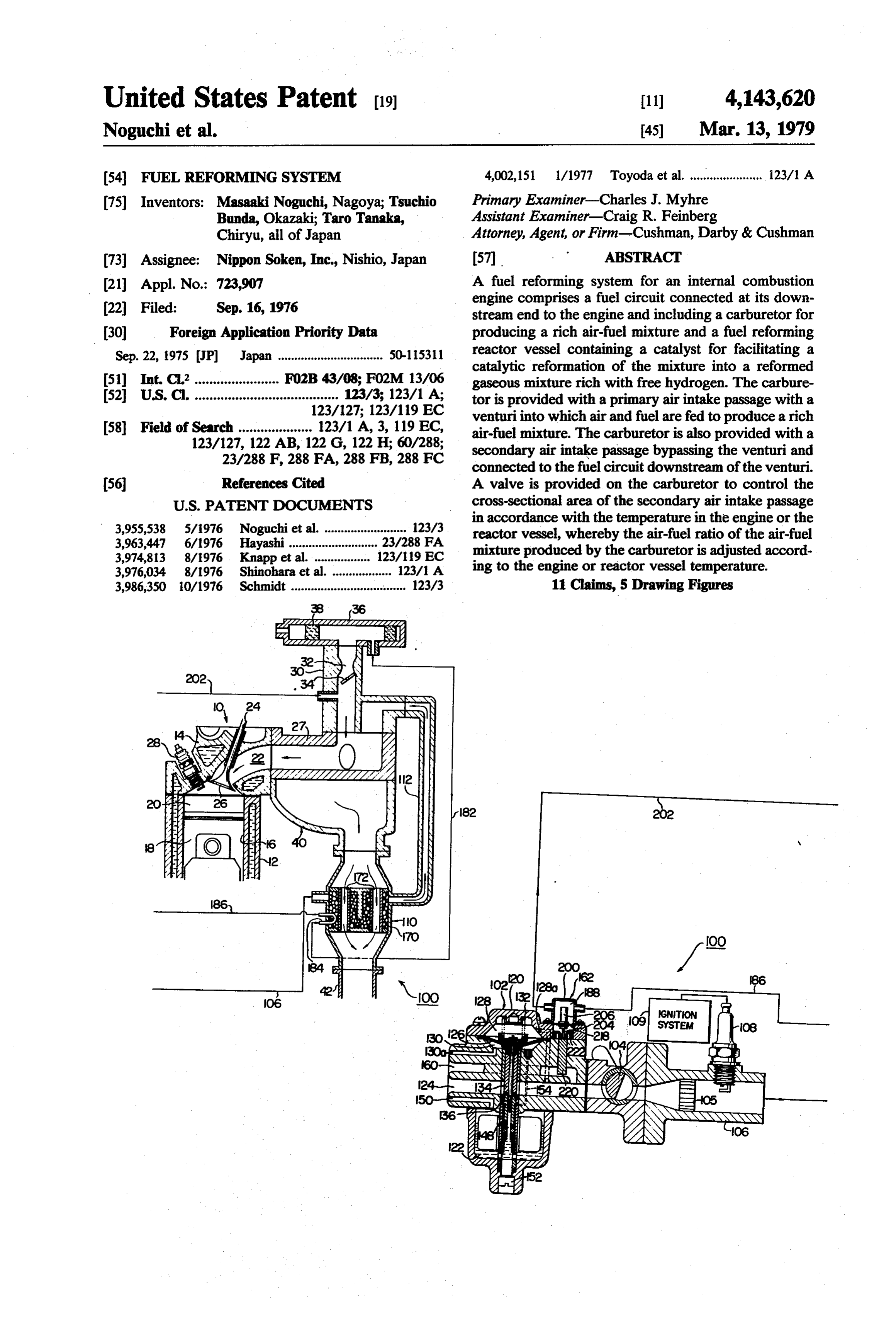
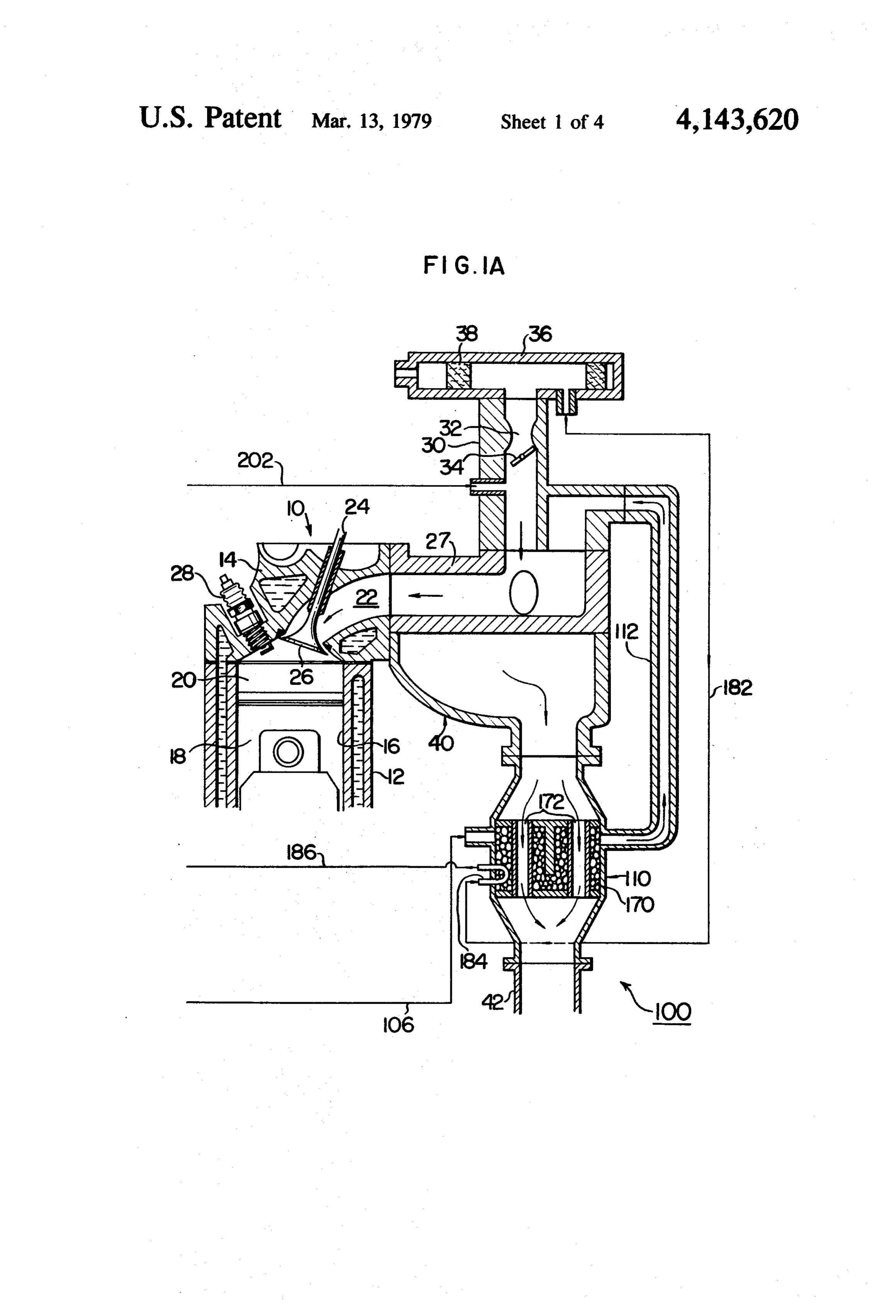
reformed gaseous mixture rich with free hydrogen and BRIEF DESCRIPTION OF DRAWINGS feed the reformed gaseous mixture into the engine, as 20 disclosed in U.S. Pat. No. 3,908,606 issued Sept. 30, FIG. 1A is a diagrammatic, sectional side elevational 1975 to Eiji Toyoda et al. There has also been proposed view of a part of an embodiment of a fuel reforming a fuel reforming system for an internal combustion en system according to the present invention; gine which is operative to convert a mixture of air, a FIG. 1B is an enlarged diagrammatic, sectional side fuel, such as ones referred to above, and steam (or wa 25 elevational view of the rest of the embodiment shown in ter) into a reformed gaseous mixture rich with free FIG. 1A;
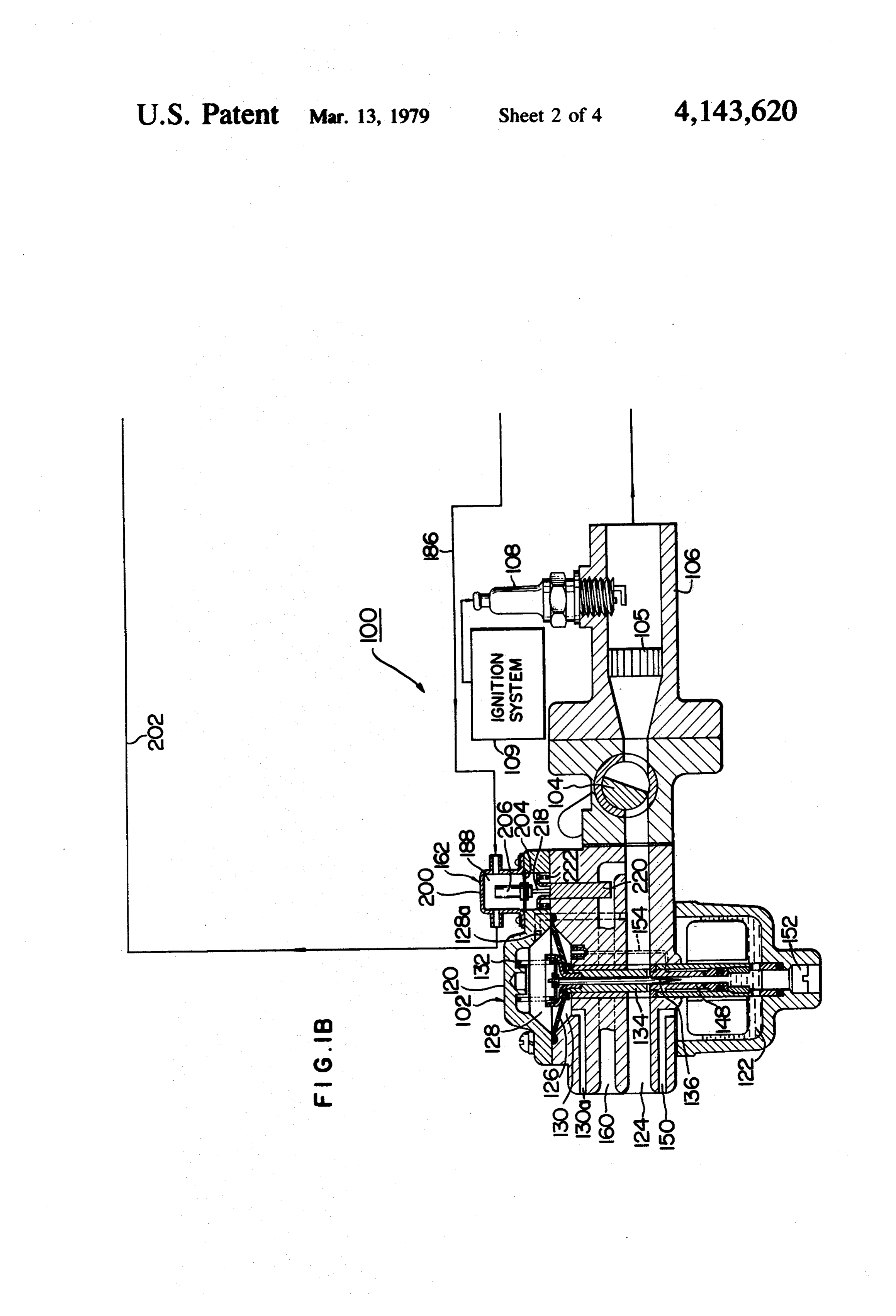
hydrogen and then introduce the reformed mixture into FIG. 2 is an enlarged, sectional side elevational view the engine. The prior art systems include reactor vessels of a heat expansible means employed in the embodiment each containing a catalyst for facilitating a fuel reform shown in FIGS. 1A and 1B:
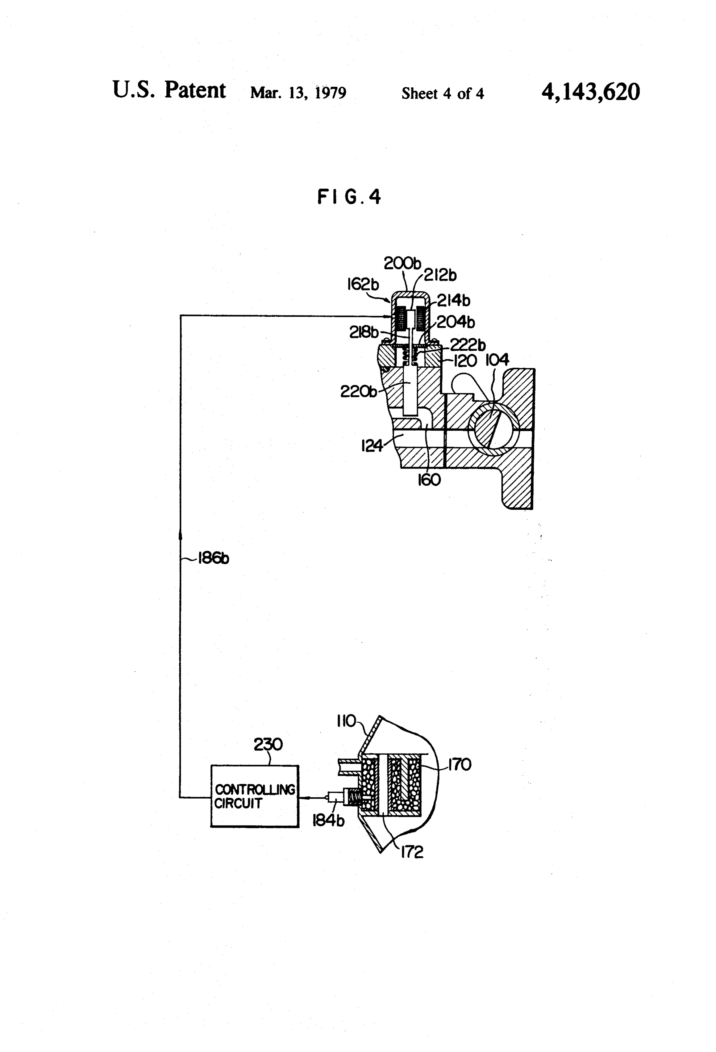
ing catalytic reaction. When or just after the engine is 30 FIG. 3 is an enlarged, sectional side elevation of a cold-started, the catalyst is at a low temperature and modified heat expansible means; and thus incapable of sufficiently facilitate the fuel reform FIG. 4 is a diagrammatic, fragmentary side eleva ing reaction. tional view of another embodiment of the invention. The applicants' co-pending earlier application Ser. DESCRIPTION OF PREFERRED No. 641,603 filed Dec. 17, 1975 discloses a fuel reform 35 EMBOOMENTS ing system for an internal combustion engine, in which a mixture of air and methanol is subjected to a catalytic Referring to FIGS. 1A, 1B and 2, a first embodiment reformation and converted into a reformed gaseous of a fuel reforming system according to the present mixture rich with free hydrogen. The reformed mixture invention is generally designated by 100 and adapted to is then fed into the engine together with another mix be used with an internal combustion engine which is ture of air and a hydrocarbon fuel. The disclosure in the generally indicated by 10 and shown as being a conven co-pending earlier application referred to is incorpo tional four cycle reciprocated piston engine which com rated herein by reference. prises a cylinder block 12 and a cylinder head 14 SUMMARY OF THE INVENTION mounted on the top of the cylinder block 12. The cylin 45 der block 12 defines therein cylinders 16 only one of
It is an object of the present invention to provide an which is shown. A piston 18 is reciprocally received in improved fuel reforming system for converting a mix the cylinder 16 to cooperate with the cylinder 16 and ture of air and a fuel into a reformed gaseous mixture the bottom surface of the cylinder head 14 to define a rich with free hydrogen and feeding the thus reformed combustion chamber 20. The cylinder head 14 is formed gaseous mixture into an internal combustion engine. 50 therein with an intake port 22 and an exhaust port (not The fuel reforming system according to the present shown). An intake valve 24 is reciprocally mounted on invention includes a fuel circuit which includes a carbu the cylinder head 14 so that a valve head 26 of the retor for producing a mixture of air and a fuel, such as intake valve is operative to open and close the intake methanol, and a fuel reforming reactor vessel contain port 22 in conventional manner. A spark plug 28 is ing therein a catalyst for facilitating a catalytic fuel 55 mounted on the cylinder head 14 so that electrodes of reforming reaction therein. The fuel circuit has its the spark plug are exposed to the combustion chamber downstream end connected to an associated internal 20.
combustion engine so that a reformed gaseous mixture The intake port 22 is connected at its upstream end produced in the fuel reforming reactor vessel is intro with an intake pipe 27 which in turn is connected at its duced into the engine. An ignition means is provided in upstream end with a primary fuel circuit comprising a the fuel circuit between the carburetor and the reactor primary carburetor 30 having a venturi 32 for produc vessel and may be operated, when required, to ignite the ing a lean mixture of air and a hydrocarbon fuel, such as air-fuel mixture produced by the carburetor. The carbu gasoline. A throttle valve 34 is provided in the primary retor is provided with a primary air intake passage with fuel circuit downstream of the venturi32 for controlling a venturi therein. The fuel is fed into the venturi so that 65 the primary fuel supply into the respective combustion the fuel is mixed with air passing through the venturi to chambers 20 in known manner. An air cleaner 36 having form the air-fuel mixture. The carburetor is also pro an air filter 38 therein is mounted on the top of the vided with a secondary air intake passage which by primary carburetor 30. Exhaust gases from respective
Page 7
exhaust ports (not shown) are gathered into an exhaust 110. Details of the air-methanol ratio adjusting means gas gathering portion 40. 162 will be described later. The fuel reforming system 100 provides a secondary The spark plug 108 is operated by a conventional fuel circuit for the engine 10 and designed to be opera ignition system 109 when required, i.e., for example tive to convert or reform a mixture of air and methanol when the reactor vessel 110 is at a low temperature, to into a reformed gaseous mixture rich with free hydro ignite and burn a part of air-methanol mixture produced gen and feed the reformed gaseous mixture into the by the secondary carburetor 102. engine 10. For this purpose, the fuel reforming system A flame arrester 105 is provided in the pipe 106 be 100 includes a secondary carburetor 102 for producing tween the rotary throttle valve 104 and the spark plug a mixture of air and methanol, a rotary throttle valve 10 108 to guard the secondary carburetor 102 against flame 104 operatively connected to the primary throttle valve or flames produced by the combustion of the air 34 by a conventional link mechanism (not shown), a methanol mixture caused by the ignition thereof by the pipe 106 connected at its upstream end to the down spark plug 108. The flame arrester 105 may be a honey stream side of the throttle valve 104, a spark plug 108 comb structure of ceramic material or made of a stack mounted on the upper side of the pipe 106, a fuel re 15 of several sheets of metal screens. forming, catalytic reactor vessel 110 connected to the The fuel reforming, catalytic reactor vessel 110 is downstream end of the pipe 106, and a second pipe 112 connected to the exhaust gas gathering portion 40 of the extending between the reactor vessel 110 and the pri exhaust manifold and contains a layer 170 of catalyst mary fuel circuit at a point between the primary throttle particles. The layer 170 extends substantially across the valve 34 and the intake pipe 28. 20 entire cross-sectional area of the vessel 110. The air The secondary carburetor 102 is of constant vacuum, methanol mixture produced by the secondary carbure horizontal draft type and comprises a carburetor hous tor 102 flows through the pipe 106 into the layer 70 of ing 120 which defines therein a float chamber 122 on the the catalyst particles. A plurality of axial passages 172 under side of a primary air intake passage 124 and a extend through the catalyst particle layer 170 so that space on the upper side of the air intake passage 124. A 25 exhaust gases from the engine 10 flow from the exhaust diaphragm 126 extends substantially horizontally across gas gathering portion 40 into and through the axial the space to divide the same into a first or upper pres passages 172 in heat exchanging relationship with the sure chamber 128 and a second or lower pressure cham catalyst particle layer 170 and the air-methanol mixture ber 130. A compression coil spring 132 is disposed in the flowing therethrough. Thus, the catalyst particles are first pressure chamber 128 to downwardly bias the dia 30 heated to a temperature sufficient for the catalytic ref phragm 126. A suction piston 134 is mounted on the ormation or conversion of the air-methanol mixture into under surface of the diaphragm 126 and slidably extends a reformed gaseous mixture rich with free hydrogen, through the carburetor 102 and across the air intake which is then supplied through the pipe 112 into the passage 124 toward the float chamber 122. A needle 136 primary fuel circuit and introduced into the engine 10 is also mounted on the diaphragm 126 coaxially with the 35 together with a lean air-gasoline mixture from the pri suction piston 134 and reciprocally extends into an mary carburetor 30. The engine exhaust gases flow opening of a nozzle 148 extending from the air intake from the vessel 110 into and through an exhaust pipe 42 passage 124 into the float chamber 122 and terminating and are then exhausted into the atmosphere. in an open bottomed end positioned adjacent to the The construction and operation of the fuel reforming, bottom of the float chamber 122. The first chamber 128 catalytic reactor vessel 110 may be similar to those is communicated by a passage 128a with the air intake disclosed in U.S. patent application Ser. No. 641,603 passage 124 downstream of the suction piston 134, referred to above. Preferred examples of the catalyst while the second chamber 130 is communicated with particles which form the layer 170 are pellets of alumina the atmosphere by a passage 130a. The suction piston coated with a metal such as nickel or copper. 134 is arranged such that the differential pressure in the 45 The air-methanol ratio adjusting means 162 men air intake passage 124 across the suction piston 134 is tioned above include an air conduit 182 interconnecting kept at a constant value which is determined by the load the interior of the air cleaner 36 and one end of a ten on the diaphragm 126 exerted by the spring 132 thereto. perature detector in the form of a U-shaped tube 184 of In other words, the suction piston 134 cooperates with a metal mounted on the reactor vessel 110 with the the air intake passage 124 to define a variable venturi 50 looped end of the tube extending into the layer 170 of the opening of which is determined by the air flow the catalyst particles in the vessel 110 so that the air through the passage 124. The fuel is fed from the float from the air cleaner 36 flows through the temperature chamber 122 through the nozzle 148 into the venturi so detector 184 in heat-exchange relationship with the that a mixture of air and the fuel is produced. The float catalyst particles. The air from the air cleaner 36 is chamber 122 is vented by an air vent 150 and can be 55 heated when the air flows through the temperature drained by removing a blind plug 152 from the bottom detector 184. The heated air then flows through a sec of the float chamber. The interior of the nozzle 148 is ond air conduit 186 into a temperature measuring cham communicated with the second pressure chamber 130 ber 188 defined by a housing 200, from which chamber by an air bleeder 154. A secondary air intake passage the air is returned through a third air conduit 202 into 160 extends through the secondary carburetor 102 and the primary fuel circuit of the engine 10 downstream of bypasses the venturi and is opened to the air intake the primary throttle valve 34. The housing 200 is passage 124 downstream of the venturi, i.e., at a point mounted on the carburetor housing 120. The tempera between the suction piston 134 and the rotary throttle ture measuring chamber 188 is defined between the valve 104. housing 200 and a support plate 204 extending across The secondary carburetor 102 is provided with an 65 the interior of the housing 200. The support plate 204 air-methanol ratio adjusting means 162 operative to supports an expansible means 206 which comprises a control the air flow through the bypass passage 160 in cylinder member 208 rigidly mounted on the support accordance with the temperature in the reactor vessel plate 204 by means of a stay 210, a piston reciprocally
Page 8
received within the cylinder member 208, a mass of heat expanded with resultant increase in the load on the expansible material 214 filled in the space defined be compression spring 222, which causes downward dis tween the cylinder member 208 and the piston 212, and placement of the piston-type valve 200 into the bypass a coil spring 216 urging the piston against the heat ex passage 160, whereby the cross-sectional area of the pansible material 214, as shown in FIG. 2. The heat bypass passage 160 and thus the air flow therethrough expansible material may be an inorganic compound are decreased. For the reason, the air-methanol ratio of such as MgO, a metal such as Pb or an alloyed metal the air-methanol mixture produced by the secondary such as solder (Pb-Sn). In the case where the second air carburetor 102 is gradually decreased. The secondary conduit 186 is so long that the air heated during its carburetor 102 is arranged such that, when the layer 170 passage through the temperature detector 184 is sub O of the catalyst particles in the reactor vessel 110 is stantially cooled before the air reaches the temperature heated to a temperature high enough to induce a fuel measuring chamber 188, the heat expansible material reforming reaction (i.e., a temperature of about 350 C. may preferably be paraffin or a wax. in the case of Ni or Cu catalyst particles), the air Thus, the piston 212 will be moved downwardly methanol ratio of the air-methanol mixture produced when the heat expansible material 214 is expanded by 15 falls within a range of from 0.3 to 1.5. An air-methanol the heated air supplied to the temperature measuring mixture of as small air-methanol ratio as possible is chamber 188. The piston 212 has a piston rod 218 which preferred in the view point of avoiding loss of chemical is in engagement with the upper surface of a piston-type energy but should fall within a range of air-methanol valve 220 which is slidably received in a bore formed in ratio where the mixture does not produce a large the secondary carburetor 102 and has a lower valve part 20 amount of soot when the mixture is subjected to the extending into the secondary air intake or bypass pas catalytic reforming reaction.
sage 160 in the carburetor 102. It will be appreciated As such, the air-methanol mixture is converted by the that, when the heat expansible material 214 is expanded, catalytic action of the catalyst particles into a reformed the valve part of the piston-type valve 220 is moved gaseous mixture rich with free hydrogen. downwardly to decrease the sectional area of the bypass 25 The reformed gaseous mixture flows through the passage 160 to thereby decrease the air flow there pipe 112 into the intake pipe 28 of the engine 10, in through. A compression coil spring 222 is provided to which the mixture is mixed with a lean air-hydrocarbon always bias the piston-type valve 220 upwardly. fuel mixture from the primary carburetor 30 to form a The operation of the described embodiment will be composite mixture which is supplied into the combus described. At the time of, or just after the cold-starting 30 tion chamber 20. The existence of free hydrogen in the of the engine 10, the catalyst particle layer 170 in the composite mixture assures a reliable combustion of a reactor vessel 110 is at a low temperature, so that the air very lean air-fuel mixture in the combustion chamber flowing through the temperature detector 184 enters and a reduction in the emission of harmful components the temperature measuring chamber 188 at a low tem of the engine exhaust gases. It will be also apparent perature. Thus, the heat expansible material 214 in the 35 from the above description that the air-methanol mix expansible means 206 is in almost non-expanded state, so ture is converted into the reformed gaseous mixture that the lower valve part of the piston-type valve 220 is even at the time the engine is operating at a low temper in a position to substantially fully open the bypass pas ature, whereby the engine can be smoothly operated sage 160. For this reason, a relatively large amount of even from the time the engine is at a low temperature. secondary air is supplied through the bypass passage 40 The air-methanol ratio adjusting means 162 may also 160 to a rich air-methanol mixture produced by the air be operable by another high temperature fluid, such as passing through the primary air intake passage 124 and engine exhaust gas, reformed gaseous mixture or engine methanol jetted from the nozzle 148 into the air. Thus, cooling water. FIG. 3 illustrates a modified heat expan the air-methanol mixture is diluted by the secondary air sible means 206a which is particularly designed to be to an air-methanol ratio which is larger than normal 45 operable by engine exhaust gas and comprises a rod air-methanol ratio obtained during normal operation of member 214a of a heat resistant metal extending the engine, i.e., after the engine is appropriately through a temperature measuring chamber 188a defined warmed. The larger air-methanol ratio, however, is in a housing 208a which is rigidly secured or connected much smaller than the stoichiometric air-methanol ratio to a support plate 204a secured to the carburetor hous of 6.5. The arrangement is such that the air-methanol 50 ing 120. The rod member 124a is secured at its top end ratio after the rich air-methanol mixture is diluted by to the housing 208a and has a lower end portion 218a the secondary air from the bypass passage 160 ranges which is freely movable through an opening in the from 1.6 to 3.0 when the reactor vessel 110 is at a low support plate 204a. The lower end extremity of the rod temperature. Because the air-methanol ratio is relatively member 214a may be in abutment contact with the top large at the point of the spark plug 108, at least a part of 55 of the piston-type valve 220 so that the temperature the air-methanol mixture can be stably ignited by the variation in the engine exhaust gas can be directly con spark plug 108 and burnt to produce heat of reaction, verted into displacement of the valve 220 for the con whereby a fuel reforming reaction can surely be in trol of the cross-sectional area of the bypass passage duced in the reactor vessel 110 to reliably produce a 160, as in the embodiment described with reference to reformed gaseous mixture rich with free hydrogen even FIGS. 1A, 1B and 2.
when the reactor vessel 110 is at the low temperature. FIG. 4 illustrates a further modification of the air By a continued operation of the engine, the layer 170 methanol ratio adjusting means generally designated by of the catalyst particles in the reactor vessel 110 is 162b, in which the temperature in the fuel reforming heated to an elevated temperature with the result that reactor vessel 110 is electrically detected to control the the air passing through the temperature detector 184 is 65 cross-sectional area of the bypass passage 160. For this also heated. The heated air is introduced into the tem purpose, the modified air-methanol ratio adjusting perature measuring chamber 188, so that the heat expan means 162b includes an electric temperature detector sible material 214 of the heat expansible means 216 is 184b in the form of a conventional thermistor or a ther
Page 9
mocouple which is mounted on the reactor vessel 110 to mixture into an internal combustion engine, said system detect the temperature therein and emit an electrical comprising:
signal representing the detected temperature. The elec a fuel circuit having a downstream end adapted to be trical temperature signal is supplied to a controlling connected to an internal combustion engine; circuit 230 which is operative to compare the signal s a carburetor disposed in said fuel circuit for produc with a reference signal and decide as to whether or not ing a rich mixture of air and the fuel at an air-fuel the temperature in the reactor vessel 110 is high enough ratio smaller than the stoichiometric air-fuel ratio to achieve the catalytic reformation of the air-methanol of the mixture;
mixture into the required reformed gaseous mixture. said carburetor including a primary air intake pas The controlling circuit 230 is electrically connected by O sage, means providing a venturi in said air intake a line 186b to an electromagnetic coil 214b mounted in passage, means for feeding the fuel into said venturi a housing 200b which is secured to the carburetor hous substantially in proportion to the flow of air ing 120. A core 212b is movably disposed within the coil through said venturi to cooperate therewith to 214b and connected by a rod 218b to a piston-type valve 15 produce the rich air-fuel mixture, and a secondary 220b which is adapted to be moved into and out of the air intake passage bypassing said venturi and con bypass passage 160 in the secondary carburetor 102. A nected to said fuel circuit downstream of said ven compression coil spring 222b extends around the rod turi for supplying a secondary air to the rich air 218b between the valve 220b and a support plate or fuel mixture produced in said venturi; spring retainer plate 204b secured to the carburetor 20 ignition means disposed in said fuel circuit down stream of said carburetor and being adapted to be housing 120, the rod 218b slidably extending through operated, when required, to ignite and burn the the spring retainer plate 204b. The arrangement is such air-fuel mixture in said fuel circuit; that the electromagnetic coil 214b is energized by an a reactor vessel disposed in said fuel circuit and con electric current from the controlling circuit 230 during taining therein a catalyst for facilitating a catalytic normal operation of the engine and deemergized when 25 reformation of said rich air-fuel mixture into said the temperature signal received by the controlling cir reformed gaseous mixture, said catalyst being dis cuit 230 indicates that the temperature in the reactor posed in heat exchange relationship with engine vessel 110 is not high enough for the intended catalytic exhaust gases; and reformation of the air-methanol mixture in the vessel.
The air-methanol ratio adjusting means 162b discussed 30 air-fuel ratio adjusting means mounted on said carbu retor and being operative in response to the varia above will be operative in a manner substantially simi tion in the temperature of said reactor vessel to lar, but not exactly similar, to that of the preceding vary the cross-sectional area of said secondary air embodiments. In the embodiment discussed with refer intake passage for thereby controlling the air-fuel ence to FIG. 4, the electromagnetic coil 214b is ener ratio of said rich air-fuel mixture so that when said gized and deenergized according to whether the tem 35 temperature is not high enough to activate said perature in the layer 170 of the catalyst particles in the catalyst, the air-fuel ratio of the rich mixture con reactor vessel 110 exceeds the predetermined tempera trolled by said air-fuel ratio adjusting means is ture or not. However, the controlling circuit 230 may controlled to allow a part of the mixture to be be modified such that its output gradually and continu ignited by said ignition means to produce heat ously varies in proportion to the variation in the temper which raises the temperature of said reactor vessel, ature within the reactor vessel 110 so that the air and when said temperature in the reactor vessel is methanol ratio adjusting means 162b is operative in an high enough to activate said catalyst, the mixture is exactly similar manner to that of the preceding embodi further enriched to the extent that the temperature nets. is not further increased above a point where the Embodiments of the invention have been described 45 reformation is substantially at a maximum. and illustrated as being used with a conventional, spark 2. A fuel reforming system according to claim 1, ignition internal combustion engine. However, it will be wherein said ignition means comprise a spark plug dis apparent to those skilled in the art that the fuel reform posed on the upper side of a passage defined in said fuel ing system according to the present invention can also circuit.
be used with a torch-ignition internal combustion en 50 3. A fuel reforming system according to claim 1, gine having an auxiliary combustion chamber. In this wherein said fuel is methanol.
instance, the reformed gaseous mixture may effectively 4. A fuel reforming system according to claim 1, be fed into the auxiliary combustion chamber for igni wherein said air-fuel ratio adjusting means is operative tion and combustion by a spark plug, while a lean mix in response to the increase in the temperature of engine ture of air and a hydrocarbon fuel may be supplied to a 55 exhaust gases.
main combustion chamber of the engine for the ignition 5. A fuel reforming system according to claim 1, and combustion by a torch jet or jets produced by the wherein said catalyst contains at least one of nickel and combustion of the reformed gaseous mixture. copper.
It will also be apparent to those in the art that the 6. A fuel reforming system according to claim 1, constant vacuum, horizontal draft type secondary car 60 wherein said air-fuel ratio adjusting means includes buretor 102 employed in the described embodiments of valve means for controlling the cross-sectional area of the present invention may be replaced by a conven said secondary intake passage, means for actuating said tional down-draft type carburetor, which provides sub valve means, a temperature detector mounted on said stantially similar results. reactor vessel to detect the temperature in said reactor What is claimed is: 65 vessel for thereby emitting an electrical output signal 1. A fuel reforming system for converting a mixture representing the detected temperature, and means re of air and a fuel into a reformed gaseous mixture rich sponsive to the electrical output signal to control said with free hydrogen and feeding the reformed gaseous valve means actuating means; said valve means being
Page 10
controlled to decrease the cross-sectional area of said take passage downstream of said venturi to supply secondary air intake passage to decrease the air-fuel a secondary air to the rich air-fuel mixture pro ratio of the mixture produced in said venturi as the duced in said venturi, a temperature measuring temperature in said reactor vessel rises. chamber adjacent said secondary air intake pas 7. A fuel reforming system according to claim 1, 5 sage, means disposed in said temperature measur wherein said carburetor is disposed such that said pri ing chamber and being expansible and contractible mary air intake passage extends substantially horizon in response to the variation in the temperature in tally. said temperature measuring chamber, and a valve 8. A fuel reforming system according to claim 2, member operatively associated with said expansi wherein said venturi providing means comprise a suc 10 ble and contractible means to control the cross-sec tion piston disposed in said primary air intake passage tional area of said secondary air intake passage for for movement in a direction transverse of the axis thereby controlling the air-fuel ratio of the air-fuel thereof. mixture produced in said venturi; 9. A fuel reforming system for converting a mixture a throttle valve disposed in said fuel circuit down of air and a fuel into a reformed gaseous mixture rich 15 stream of said carburetor; with free hydrogen and feeding the reformed gaseous a spark plug disposed in said fuel circuit downstream mixture into an internal combustion engine, said system of said throttle valve and being adapted to be oper comprising: ated, when required, to ignite and burn the rich a fuel circuit having a downstream end adapted to be air-fuel mixture;
connected to an internal combustion engine; 20 a reactor vessel disposed in said fuel circuit down a carburetor disposed in said fuel circuit for produc stream of said spark plug and containing a catalyst ing a rich mixture of air and the fuel at an air-fuel for facilitating a catalytic reformation of the air ratio smaller than the stoichiometric air-fuel ratio fuel mixture into the reformed gaseous mixture; of the mixture; and said carburetor comprising a substantially horizontal 25 means for causing atmospheric air to flow through primary air intake passage, a substantially closed said reactor vessel in heat exchange relationship space, a diaphragm extending across said space to with said catalyst and then through said tempera divide the same into upper and lower chambers, a ture measuring chamber; said carburetor being suction piston connected at one end to said dia arranged such that, when said catalyst is at a first phragm and extending into said primary air intake 30 temperature high enough to activate said catalyst, passage for movement transversely of the axis the air-fuel ratio of the mixture controlled by said thereof to provide a variable venturi in said pri valve member is much smaller than the stoichio mary air intake passage, a second passage intercon metric air-fuel ratio of the mixture and such that, necting said upper chamber and said primary air when said catalyst is at a second temperature lower intake passage downstream of said venturi, a third 35 than said first temperature, the air-fuel ratio of the passage communicating said lower chamber and mixture controlled by said valve member is still the atmosphere, spring member disposed in said smaller than the stoichiometric air-fuel ratio but so upper chamber for downwardly urging said dia large as to allow a part of the mixture to be ignited phragm, a float chamber for said fuel, a nozzle by said spark plug to produce heat in said fuel extending from said float chamber to said venturi 40 circuit.
and open to said venturi to cooperate therewith to 10. A fuel reforming system according to claim 9, produce the rich air-fuel mixture, a needle movable wherein said fuel is methanol.
with said suction piston to control the cross-sec 11. A fuel reforming system according to claim 9, tional area of the opening of said nozzle in said wherein said catalyst contains at least one of nickel and venturi, a secondary air intake passage bypassing 45 copper.
said venturi and connected to said primary air in
Provenance
- Collection
- Cited prior art
- Original PDF
- patentimages.storage.googleapis.com →
- Filed
- 1976-09-16
- Pages
- 10
- Method
- pdftotext (the PDF's own text layer) + pdftoppm 300dpi page scans
- Source
- Google Patents bibliographic record
- Granted
- 1979-03-13
- Inventors
- Masaaki Noguchi; Tsuchio Bunda; Taro Tanaka; Nippon Soken Inc
- Transcribed from
- patentimages.storage.googleapis.com →