patent · US3792688
Anti-pollution gasified liquid fuel system
19 February 1974
Page 1 — bibliographic record
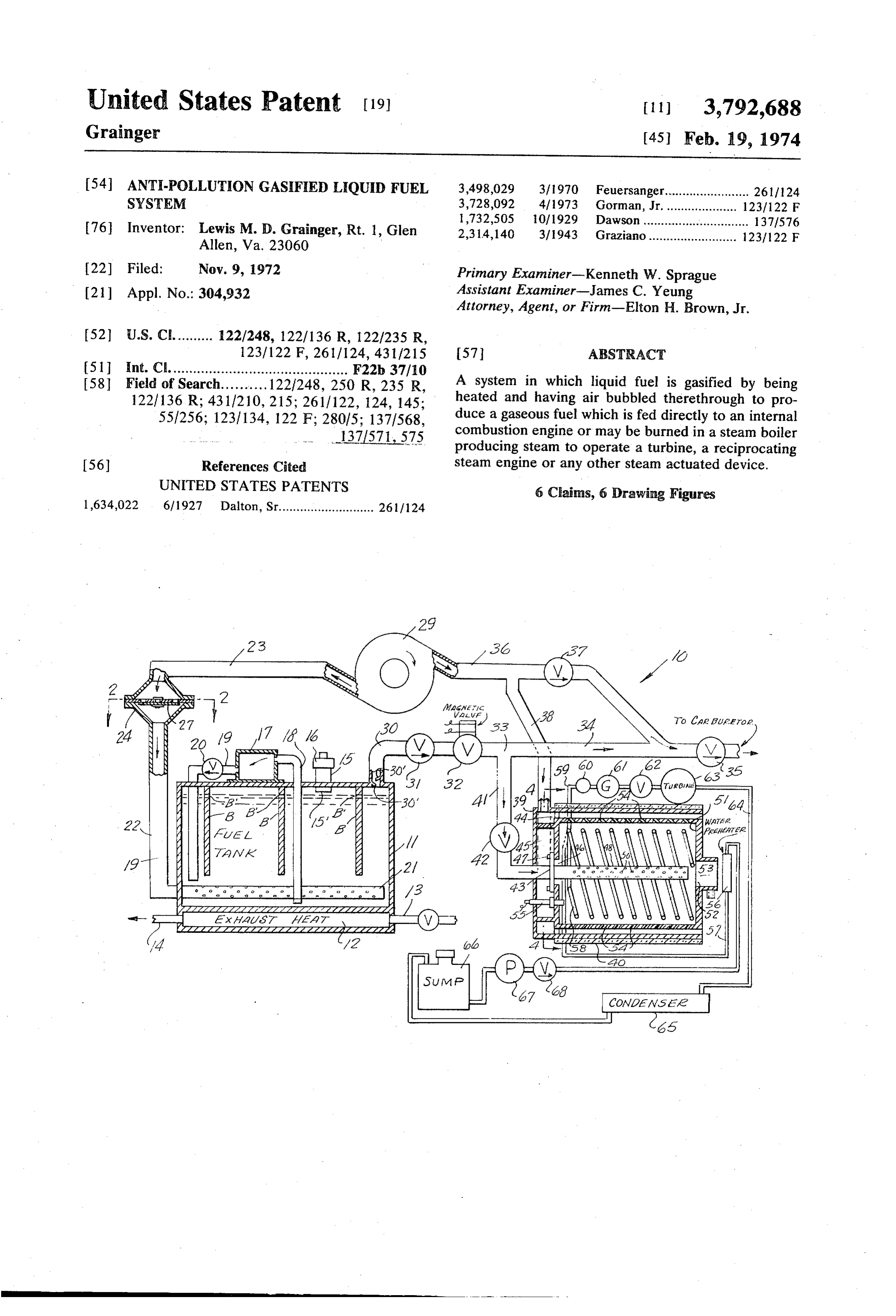
United States Patent (19) [11] 3,792,688 Grainger
54 ANTI-POLLUTION GASIFIED LEQUID FUEL 3,498,029 3, 1970 Feuersanger........................ 2611124 SYSTEM 3,728,092 4, 1973 Gorman, Jr. .................... 123/122 F 1,732,505 10, 1929 Dawson .............................. 137.1576 76 Inventor: Lewis M. D. Grainger, Rt. 1, Glen 2,314,140 3/1943 Graziano......................... 123/122 F
22 Filed Nov. 9, 1972 Primary Examiner-Kenneth W. Sprague 21 Appl. No.: 304,932 Assistant Examiner-James C. Yeung Attorney, Agent, or Firm-Elton H. Brown, Jr.
123/122 F, 261/124, 431/215 57 ABSTRACT (51 int. Cl. ............................................ F22b 37/10 58 Field of Search.......... 1221248, 250 R, 235 R, A system in which liquid fuel is gasified by being 1221 136 R; 4311210, 215; 2611122, 124, 14.5; heated and having air bubbled therethrough to pro 551256; 1231134, 122 F; 280/5; 1371568, duce a gaseous fuel which is fed directly to an internal 1371571, 575 combustion engine or may be burned in a steam boiler producing steam to operate a turbine, a reciprocating 56) References Cited steam engine or any other steam actuated device. UNITED STATES PATENTS 6 Chains, 6 Drawing Figures 1,634,022 6, 1927 Dalton, Sr........................... 2611124
- zzaszkazaszyzazatzac, RA7A/2
Page 2
Drawing sheet — no readable text.
Page 3
Drawing sheet — no readable text.
Page 4
ANTI-POLLUTION GASIFIED LIQUID FUEL bottom of the tank 11 into the top of the expansion
SYSTEM
tank 17. The drain pipe 19 extends from the bottom of the expansion tank 17 through a one way check valve
BACKGROUND OF THE INVENTION 20 discharging adjacent the bottom of the tank 11. A 1. Field of the Invention perforated bubble pipe 21 extends longitudinally across the bottom of the tank 11 and is connected to an air
The present invention relates to anti-pollution fuel supply pipe 22 at one end thereof. The air supply pipe systems utilizing gasified liquid fuel. 22 is connected to an air conduit 23 through a one way 2. Summary of the Invention valve 24 interposed therebetween. The one way valve The fuel tank of the system is heated first by an elec- 10 24 includes a transverse plate 25 having a plurality of tric heater to begin the gasification followed by exhaust gas heat or in a modified form completely by an electric apertures stream 26 formed therein and covered on the down side with a flexible diaphragm 27 secured heater and simultaneously air is bubbled through the thereto by a bolt 28. Air flowing from the air conduit liquid fuel to produce a gaseous fuel which is fed di 23 to the air supply pipe 22 forces the diaphragm 27 rectly to the carburetor of an internal combustion en- 15 downwardly away from the apertures 26 but reversed gine or to the burner of a steam generator with the steam being used to drive a reciprocating steam engine flow is prevented since movement of air in a reversed direction would immediately cause the diaphragm 27 or a turbine.
The primary object of the invention is to provide an isto seal against the aperture 26. A rotary air blower 29 anti-pollution power system utilizing gasified liquid 20 thereto under to connected the air conduit 23 and supplies air pressure.
fuel.
Other objects and advantages will become apparent A fuel line 30 extends from the top of the fuel tank in the following specification when considered in the to11 prevent and has a one way check valve 31 mounted therein back flow or back fire from reaching the fuel light of the attached drawings. tank 11. Baffles 30' in the fuel line 30 prevent liquid
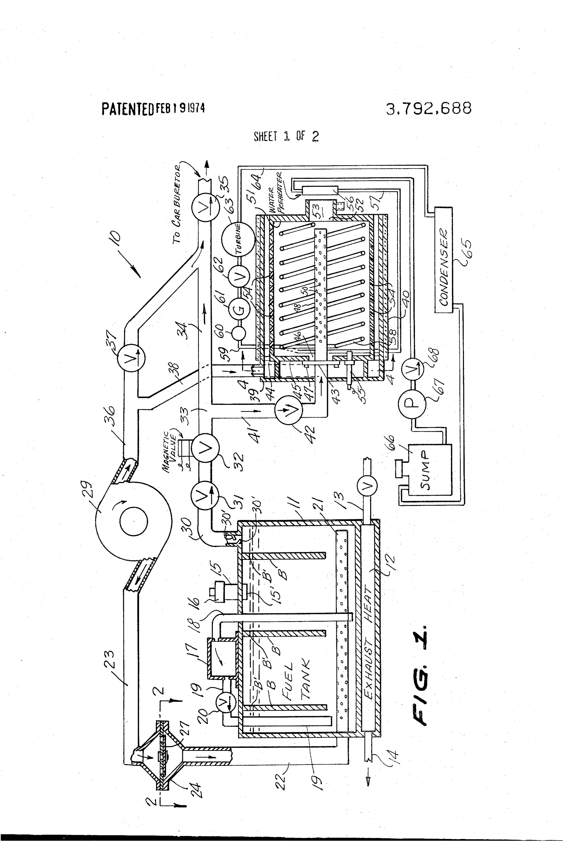
BRIEF DESCRIPTION OF THE DRAWINGS fuel from being splashed into the fuel line 30 to elimi nate the possibility of the liquid fuel from becoming en
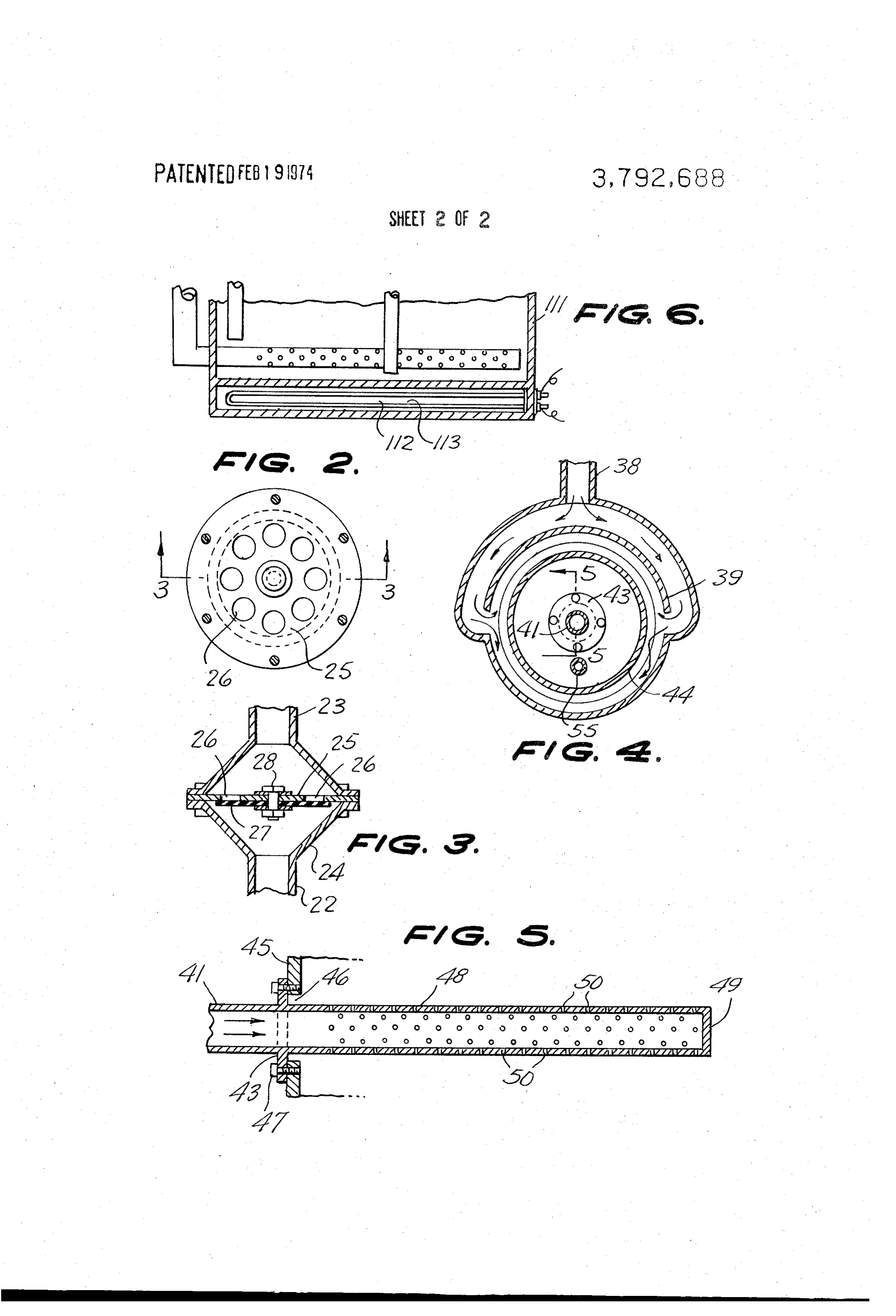
FIG. 1 is a side elevation of the invention shown par trained in the gaseous fuel moving through the fuel line tially broken away and in section for convenience of 30. A magnetic valve 32 is also interposed in the fuel illustration; line 30 to be opened only when the electric circuits in FIG. 2 is a horizontal sectional view, taken along the 30 volved line 2-2 of FIG. 1, looking in the direction of the ar The fuelarelineenergized and is closed at all other times. 30 has a tee 33 formed therein and a fuel rows;
FIG. 3 is a vertical sectional view, taken along the line branch 34 extends to a one way valve 35 to the line 3-3 of FIG. 2, looking in the direction of the ar conduit 36 of carburetor an internal combustion engine. An air extends from the air blower 29 through a rows; 35 valve 37 and is coupled to the branch fuel line 34 to
FIG. 4 is a transverse sectional view, taken along the mix additional air therewith for combustion in the en line 4-4 of FIG. 1, looking in the direction of the ar gine. A branch air conduit 38 extends from the air con rows;
FIG. 5 is a longitudinal sectional view, taken through duit ing 36 to a generally cylindrical housing 39. The hous 39 has an insulating cover 40 extending thereabout.
the gas burner; and 40
FIG. 6 is a fragmentary view similar to FIG. 1 illus A branch fuel line 41 extends from the tee 33 trating a modified form of the invention. through a one way valve 42 and then through the axial DESCRIPTION OF THE PREFERRED center of the housing 39 and carries a flange 43 rigidly EMBODIMENT 45 secured thereto. A combustion chamber 44 is mounted Referring now to the drawings in detail, wherein like within the housing 39 and spaced inwardly therefrom reference characters indicate like parts throughout the therein.anThe having end wall 45 with an axial opening 46 formed several figures, the reference numeral 10 indicates gen a plurality offlange bolts 43 is secured to the end wall 45 by 47 and a tubular gas burner 48 ex erally an anti-pollution power system constructed in ac 50 tends into the combustion chamber 44 axially thereof. cordance with the invention.
The anti-pollution power system 10 includes a com 5 is closed at 49 at its inner can
The tubular gas burner 48 as be clearly seen in FIG.
pletely sealed fuel tank 11 having a sealed compart gas outlets 50 formed throughoutand end has a plurality of ment 12 forming a part thereof to receive exhaust gases bustion chamber 44 has a second end wall 51Thewith its length. com
from an internal combustion engine through an exhaust 55 outlet opening 52 formed therein carrying an outlet pipe 13 with the exhaust gases being discharged nozzle 53. The combustion chamber 44 has a plurality through a tail pipe 14 extending from the compartment of tangentially and inwardly sloping air inlet bores 54 12. A fuel filler neck 15 is connected to the tank 11 and extending therethrough to permit a flow of air from the is closed by a seal filler cap 16 provided with an excess housing 39 to flow therein to mix with the gas flowing pressure relief valve to serve as a safety should the pres out of the apertures 50 to provide complete combus sure in the tank 11 exceed safety limits. The fuel filler 60 tion neck 15 has an extension 15 which projects below the tiallythereof. The bores 54 sloping inwardly and tangen cause a tremendous turbulence within the com top of the tank 11 to prevent the tank 11 from becom bustion chamber 44 to assist in the combustion. An ing completely filled with liquid fuel. Thus space for the electric ignitor 55 extends through the end wall 45 and formation of gaseous fuel is always available at the top is the housing 39 to ignite the gas within the combustion of the tank 11.
chamber 44 at the beginning of a heating cycle.
An expansion tank 17 is secured to the top of the A water pre-heater 56 is positioned in the stream of tank 11 and a pipe 18 extends from a point adjacent the the exhaust gases flowing out the exhaust nozzle 53 to
Page 5
pre-heat water flowing through a pipe 57 to a pair of structural modifications and adaptations may be re stream coils 58 extending spirally in the combustion sorted to without departing from the spirit of the inven chamber 44. Steam from the coils 58 flows through a tion.
steam pipe 59 to a buffer 60, pressure gauge 61, control What is claimed is:
valve 62, to a turbine 63 or in the alternative a recipro- 5 1. A power system utilizing gasified liquid fuel com cating steam engine. Exhaust steam flows through an prising a fuel tank, means for heating the fuel tank, exhaust steam pipe 64 to a condensor 65 and from means bubbling air through the fuel in the fuel tank, a there to a sump 66. A pump 67 is supplied from the fuel line extending from the top of the fuel tank for sump 66 and forces the water through a one way valve conducting gasified-liquid fuel mixed with air, means 68 to the water pre-heater 56. The steam system of the 10 for supplying air under pressure to the means for bub present invention is closed and occasional additions of bling air through the fuel in the fuel tank, a steam gen water to the sump 66 is all that is required. erator including a combustion chamber, an outer hous While I have disclosed the use of water in the steam ing surrounding said combustion chamber in spaced re system it should be understood that any combination of lation thereto, means for supplying air under pressure water and emulsifiers may be used as desired. 15 to said outer housing, a plurality of inwardly and tan In FIG. 6 a modified form of the invention is illus gentially sloping apertures in said combustion chamber trated wherein the fuel tank 11 has a compartment for conducting air from said outer housing into the 112 at the base thereof with an electric heating element inner portion of said combustion chamber, a gas burner 113 mounted in the compartment 112 to heat the fuel in said combustion chamber connected to the fuel line in the tank 111. The compartment 112 and heating ele 20 extending from said fuel tank, and means in said com ment 113 replace the exhaust heat system of the form bustion chamber for generating steam therein. of the invention illustrated in FIG. 1 with no other 2. A device as claimed in claim 1 wherein the means changes of any kind occurring. for heating air in the fuel tank comprises an exhaust gas In the use and operation of the invention the fuel in heat exchanger connected to said fuel tank. the fuel tank 11 is first heated by an electric heater (not 25 3. A device as claimed in claim wherein the means shown) to begin gasification followed by the exhaust for heating the fuel tank comprises an electric heater gase heat in the compartment 12. Air is bubbled in secured to said fuel tank.
through the bubble pipe 21 to provide a gaseous fuel 4. A device as claimed in claim 1 including an expan mixture flowing through the fuel line 30 to supply heat sion tank secured to said fuel tank, means extending to the steam generator or fuel to the carburator. An air 30 from the bottom portion of said fuel tank to said expan blower 29 provides air under pressure to the bubble sion tank for conducting liquid fuel under pressure pipe 21 and also to the fuel line 34 as well as to the from said fuel tank to said expansion tank, and means outer housing in the steam generator to provide the re extending from said expansion tank to the lower por quired air for the system. tion of said fuel tank for conducting liquid fuel from No evaporation of fuel reaches the atmosphere and 35 said expansion tank back to said fuel tank when the over expansion of fuel in the tank 11 moves into the ex pressure in said fuel tank is lowered. pansion tank 17 rather than being wasted. After the pressure falls in the fuel tank 11 gas in the expansion in 5.saidA device as claimed in claim 1 wherein the means combustion chamber for generating steam com tank 17 can flow through the pipe 19 and valve 20 back prises a sloping spiral steam coil extending longitudi to the fuel tank 11. Conventional anti-splash baffles B 40 nally therein.
having circulation bores B' in their upper ends are posi 6. A device as claimed in claim 5 including a water tioned in the tank 11. pre-heater for pre-heating water prior to entry into said Having thus described the preferred embodiment of steam coil.
the invention it should be understood that numerous : ; ; ; ;
Provenance
- Collection
- Cited prior art
- Original PDF
- patentimages.storage.googleapis.com →
- Filed
- 1972-11-09
- Pages
- 5
- Method
- pdftotext (the PDF's own text layer) + pdftoppm 300dpi page scans
- Source
- Google Patents bibliographic record
- Granted
- 1974-02-19
- Inventors
- L Grainger
- Transcribed from
- patentimages.storage.googleapis.com →