patent · US4890599
Solar panel mounting assembly
2 January 1990
Page 1 — bibliographic record
United States Patent (19) 11 Patent Number: 4,890,599 Eiden 45 Date of Patent: Jan. 2, 1990 54 SOLARPANEL MOUNTING ASSEMBLY 325983 9/1930 United Kingdom ................ 248/185 76 Inventor: Glenn E. Eiden, 302 U.S. 30 East, Primary Examiner-Noah P. Kamen New Haven, Ind. 46774 Attorney, Agent, or Firm--George Pappas (21) Appl. No.: 193,292 57 ABSTRACT (22 Filed: May 11, 1988 A solar tracking control system selectively energizes and deenergizes a motor. The motor causes a rotatable
Related U.S. Application Data shaft supported on a base and situated parallel to the earth's axis of rotation to be rotated. A U-member is 63 Continuation-in-part of Ser. No. 40,368, Apr. 16, 1987, connected to the rotatable shaft and to a frame upon
which there is mounted a solar panel or collector. A 51 Int. Cl."................................................. F24J 2/38 bracket is connected to each of the two U-member legs 52 U.S. Cl. .................................... 126/424; 126/425; and to the frame. Two reinforcing walls are connected
58 Field of Search .................... 126/424, 425; 74/89; to the U-member, legs and the U-member middle por 248/122, 183, 186, 278, 184, 185; 250/203 R; tion so as to reinforce and retain the U-member shape. 343/878,912, 757, 763, 766, 882; 350/637; By selectively rotating the rotatable shaft, the solar 353/3 panel or collector is pivoted in a substantially perpen dicular position to the sun throughout the day. In an (56) References Cited other mounting assembly, the frame is connected to a
3,889,531 6/1975 Suga ...................................... 73/150 tant angle displacement holes. A second plate is con 4,090,498 5/1978 Benson ... 126/271 nected to the base and has a pivot hole and an angle 4,202,321 5/1980 Volna .................................. 26/425 displacement hole. A pivot shaft is received through the 4,276,872 7/1981 Blake et al. ......................... 26/425 pivot holes thereby allowing the frame to pivot. An 4,295,621 10/1981 Siryj.................................... 248/183 angle displacement shaft is selectively received through 4,300,537 11/1981 Davis .................................. 126/437 the second plate angle displacement hole and any one of 4,383,520 5/1983 Huebl et al. ........................ 126/424 the first plate angle displacement holes so as to selec 4,402,582 9/1983 Rhodes ................................ 126/424 4,586,488 5/1986 Noto .................................... 126/425 tively angularly fix the frame and solar panel or collec 4,626,864 12/1986 Micklethwaite .................... 248/183 tors to more substantially be perpendicular to the sun
FOREIGN PATENT DOCUMENTS
during the various seasons of the year.
59-15306 1/1984 Japan ................................... 343/882 19 Claims, 6 Drawing Sheets
Page 2
Drawing sheet — no readable text.
Page 3
Drawing sheet — no readable text.
Page 4
Drawing sheet — no readable text.
Page 5
EEEEE E E& E E EEE EEE EEEEE EE E
di di di di di c. c. d. c. d. c. c. a. d. c. c. c. d d di di di o o d O. O. O. O. O. O. O. O. O. O. o O O. O. O. O. O. O. O. O. O. O. O. O. O
N. cood go Q - cu no sit to to N. oo odd as Q - en rott to to N
Hill
SIGNAL
AHITI
MOTOR ENERGIZE
rintin
EXNOR 54
OUTPUT
MOTOR ENERGIZE
SGNAL
Page 6
Drawing sheet — no readable text.

Page 7
Drawing sheet — no readable text.
Page 8
provide an inexpensive and yet accurate solar tracking
SOLARPANEL MOUNTING ASSEMBLY control system minimizing mechanical parts so as to decrease the probability of breakdown.
This application is a continuation-in-part of applica It is also the object of this invention to provide a solar tion Ser. No. 040,368 filed Apr. 16, 1987, now U.S. Pat. 5 panel mounting assembly whereby a solar panel can be No. 4,794,909. pivotally mounted to a support and be rigid and struc turally sound so as to be capable of withstanding forces
BACKGROUND OF THE INVENTION to which the solar panel is subjected and caused The present invention relates to a solar tracking con through wind, snow, storms, etc. Further, it is the ob trol system for controlling the position of a solar panel O ject of the present invention to provide a mounting so that the solar panel is generally situated substantially assembly which is not only structurally sound but is also perpendicular to the sun. The present invention also substantially inexpensive to manufacture, both in terms relates to a solar panel mounting assembly for rigidly of material and time needed to assemble. mounting a solar panel to a motor shaft whereby, by SUMMARY OF THE INVENTION controlling the motor shaft rotation, the solar panel 15 connected to the mounting assembly is pivoted with the The solar tracking control system and mounting as motor shaft and situated substantially perpendicular to sembly, according to the present invention, is designed the sun. to overcome the above-discussed disadvantages associ In recent times, due to energy shortages, it has be ated with prior art solar tracking systems and assem come increasingly common to seek alternative energy 20 blies.
sources. One such energy source is the sun. Solar pan The solar tracking control system generally controls els, or collectors, have become commercially available the position of a pivotable solar panel by selectively for the purpose of drawing energy from the sun and energizing and de-energizing a motor which is con using that energy to heat water, air, or other mediums. nected to the solar panel. The pivot axis of the solar Other types of solar panels include photovoltaic devices 25 panel is situated substantially parallel to the earth's axis which directly create electrical energy from the sun's of rotation. A time controlled signal programmer is rays. Naturally, the collected energy is thereafter often provided for generating a plurality of time dependent stored in some sort of energy bank and used for heating signals which are, thereafter, utilized in generating the homes, water supplies, and powering various electrical various control signals. The signal programmer is time devices, etc. 30 dependent via a 60 Hz input from a regular house outlet. It is known that solar panels are most efficient in A means for generating periodic motor energizing sig collecting the sun's energy when they are situated sub mals generally including various gates is provided and stantially perpendicular to the sun. Further, it is known causes a cross coupled NAND gate cell to latch and, that the overall efficiency of the solar panels can be thereby, retain the motor energized and the solar panel increased by pivoting the panels throughout the day so 35 pivoting in the westerly direction. A means for detect that they are generally continually situated substantially ing the degree of pivot of the solar panel generally perpendicular to the sun. In this fashion, efficiency is including a hall effect generator and sensor and a increased and the number of solar panels for any partic counter is provided so as to detect a preselected degree ular purposes is decreased thereby also decreasing the of pivot and reset the cross coupled NAND gate cell overall cost of the system. thereby de-energizing the motor and stopping the west Various mechanisms and methods have been devel erly pivoting of the solar panel. The counter resets itself oped for controlling the pivoting of solar panels so as to when resetting the NAND gate cell thereby preparing generally continually situate the solar panels perpendic itself for the next count. This process of generating a ular to the sun. The prior art solar tracking systems motor energizing signal, causing the solar panel to pivot mostly depend on an optical system which will degrade 45 and stopping the pivoting of the solar panel in response with time due to the sun's rays, and they require adjust to the counter providing a de-energizing signal is re ment periodically. They tend to be inefficient and prone peated throughout a period during which a fixed auto to break down because very often, common motor matic signal is at zero or low thereby causing the solar clocks, mechanical parts and contacts are utilized for panel to pivot westerly generally following the sun positioning the solar panels. Further, other systems are 50 during the period of which the fixed automatic signal is set up to continuously run or operate and, therefore, ZO.
consume energy needlessly and are also more likely to The solar tracking control system is energized and break down over a period of time. deenergized in response to a power signal which is Problems also exist in the pivotal mounting of solar generated by a power signal generating means which panels so that they may effectively withstand forces 55 operates in response to a plurality of time dependent created by wind, snow, storms, etc. The prior art solar signals received from the signal programmer. In es panel mounting assemblies tend to also be bulky and sence, a power switch means which includes a coil and substantially expensive thereby generally preventing contacts are utilized for selectively providing electrical the use thereof by common households. power to the solar tracking control system in response It is, therefore, the object of this invention to provide to the power signal.
a solar tracking control system wherein the solar posi The solar panel is connected to an energy bank such tion is tracked in an efficient minimum energy consum as a water storage tank for holding the energy collected ing manner under any cloud condition. Further, it is the by the solar panels and a means for transferring the object of this invention to track the solar position in a energy from the solar panels to the energy bank, such as time dependent fashion only in a westerly direction 65 a water pump, is provided. An east/west signal generat during the day so as to eliminate backtracking which ing means is connected to the signal programmer and has often occurred with systems utilizing photosensors. generates an east/west signal in response to a plurality Further yet, it is the object of the present invention to of time dependent signals received from the signal pro
Page 9
grammer. An overload determining means such as a received through the first plate pivot hole and the sec temperature sensitive switch is connected to the storage ond plate pivot hole so that the frame can pivot with tank or the energy bank such as a water storage tank so respect to the base. An angle displacement shaft or bolt as to determine an overload, such as the occurrence of is selectively received through the second plate angle exceeding a preselected temperature or the occurrence 5 displacement hole and any one of the first plate angle of an overvoltage condition of an electrical storage displacement holes thereby selectively angularly fixing bank. A switch means is provided and is connected to the solar panel or collector to be more substantially the east/west signal generating means capable of over riding the latch means and pivoting the solar panel perpendicular the year.
to the sun during the various seasons of away from direct sunlight in response to an overload 10 In one form thereof, the present invention relates to a determination and in response to the east/west signal. A mounting assembly for pivotally connecting a solar water pump may be fluidly connected between a water panel or collector to a selectively rotatable shaft. The storage tank and the solar panel and can be selectively mounting assembly includes a frame whereupon the energized so as to transfer heat collected by the solar panel to the water storage tank upon the occurrence of 5 solar panel or collector can be mounted and a U-mem a preselected temperature difference between the solar ber having two legs connected to the frame. The two panel and the water storage tank. legs are connected to the selectively rotatable shaft and The present invention overcomes the prior art disad the solar panel or collector is pivoted by rotating the vantages by substantially eliminating mechanical parts. shaft.
Thus, the overall solar tracking system is less prone to 20 In one form thereof, the present invention relates to a breakdown. Further, the solar tracking control system mounting assembly for pivotally connecting a solar is more efficient to operate in that it is energized only panel or collector to a selectively rotatable shaft. The when needed during daylight. Further, by utilizing low mounting assembly includes a frame whereupon the energy consumption electrical parts, overall efficiency solar panel or collector is mounted. A U-member is is also increased in that when the solar tracking control 25 provided having two substantially flat legs each of system is energized, a minimal amount of energy is which have an inner face and an outer face and are consumed. In general, the solar tracking control system connected to a middle flat portion also having an inner is efficient because during the day, solar tracking occurs face and an outer face. The middle portion of the U in a time dependent fashion only in the westerly direc member tion and the solar panel is not permitted to back track legs. Twois substantially
substantially perpendicular to both of the unless an overtemperature or overload condition occurs an inner face and an outerflatfacemounting brackets having such that direct sunlight must be avoided. Further yet, mounting brackets is connected to one of theOne are provided. of the the solar tracking control system of the present inven the mounting bracket inner face opposing the onewith legs leg tion, by utilizing electrical integrated circuitry and by utilizing a signal programmer dependent on a common 35 outer face and is also connected to the frame. The other 60 Hz outlet, is generally inexpensive and yet substan mounting bracket is connected to the other of the legs tially accurate. with the mounting bracket inner face opposing the A mounting assembly is provided for more rigidly other leg outer face and is also connected to the frame. connecting the solar panel or collector to the base so as Two substantially flat reinforcing walls are also pro to withstand winds, snow, storms, etc. The mounting vided. The reinforcing walls are connected to the mid assembly includes a frame whereupon a solar panel or dle portion and both of the legs of the U-member and, collector can be mounted. A U-member having two thus, keep the legs perpendicular to the middle portion. legs interconnected by a middle portion is connected to The two legs are connected to the selectively rotatable the frame through the use of two brackets. The legs are shaft and the solar panel or collector is pivoted by rotat substantially parallel to one another and perpendicular 45 ing the shaft.
to the middle portion and, are also connected to a selec In one form thereof, the present invention relates to a tively rotatable shaft which is supported on the base. By mounting assembly for pivotally connecting a solar rotating the shaft through the use of a motor which is panel or collector to a base. The mounting assembly controlled by the solar tracking control system, the includes a frame whereupon the solar panel or collector U-member along with the frame and solar panel or 50 collector is pivoted so as to substantially follow the sun. canThe be mounted and a first plate connected to the frame.
first plate has a pivot hole and a plurality of angle
Two reinforcing walls are also provided and connected displacement holes thereon. Each of the displacement to the middle portion and both of the legs of the U holes are equidistant from the pivot hole. A second member so as to support the U-member and retain the plate is connected to the base and is situated substan legs substantially perpendicular to the middle portion. 55 tially parallel to the first plate. The second plate has a Another mounting assembly is provided for pivotally pivot hole and an angle displacement hole which are connecting a solar panel or collector to a base so as to situated substantially the same distance apart from each pivot the panel or collector throughout the various seasons. In this mounting assembly, a first plate is con other as the distance between the pivot hole and dis nected to the frame and the plate has a pivot hole and a 60 placement holes of the first plate. A pivot shaft is re plurality of angular displacement holes situated equidis ceived through the first plate pivot hole and the second tant from the pivot hole. A second plate is connected to plate pivot hole so that the frame and first plate can the base and is situated substantially parallel to the first pivot with respect to the second plate and the base. An plate and has a pivot hole and an angle displacement angle displacement shaft is selectively received through hole. The pivot hole and angle displacement hole of the 65 the second plate angle displacement hole and any one of second plate are situated substantially the same distance the first plate angle displacement holes so that the first apart as the distance between the pivot and displace plate can be selectively angularly fixed with respect to ment holes of the first plate. A pivot shaft or bolt is the second plate and the base.
Page 10
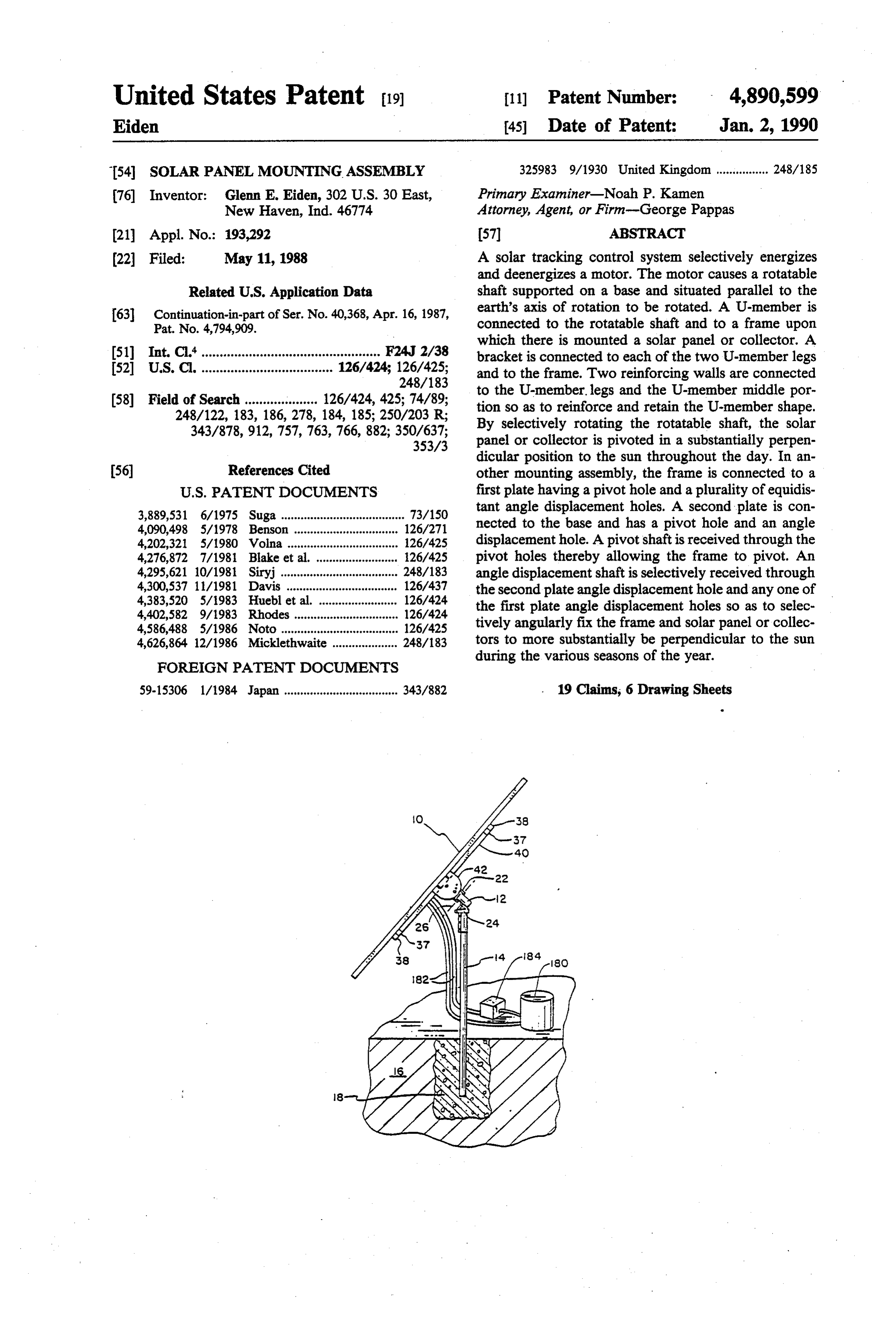
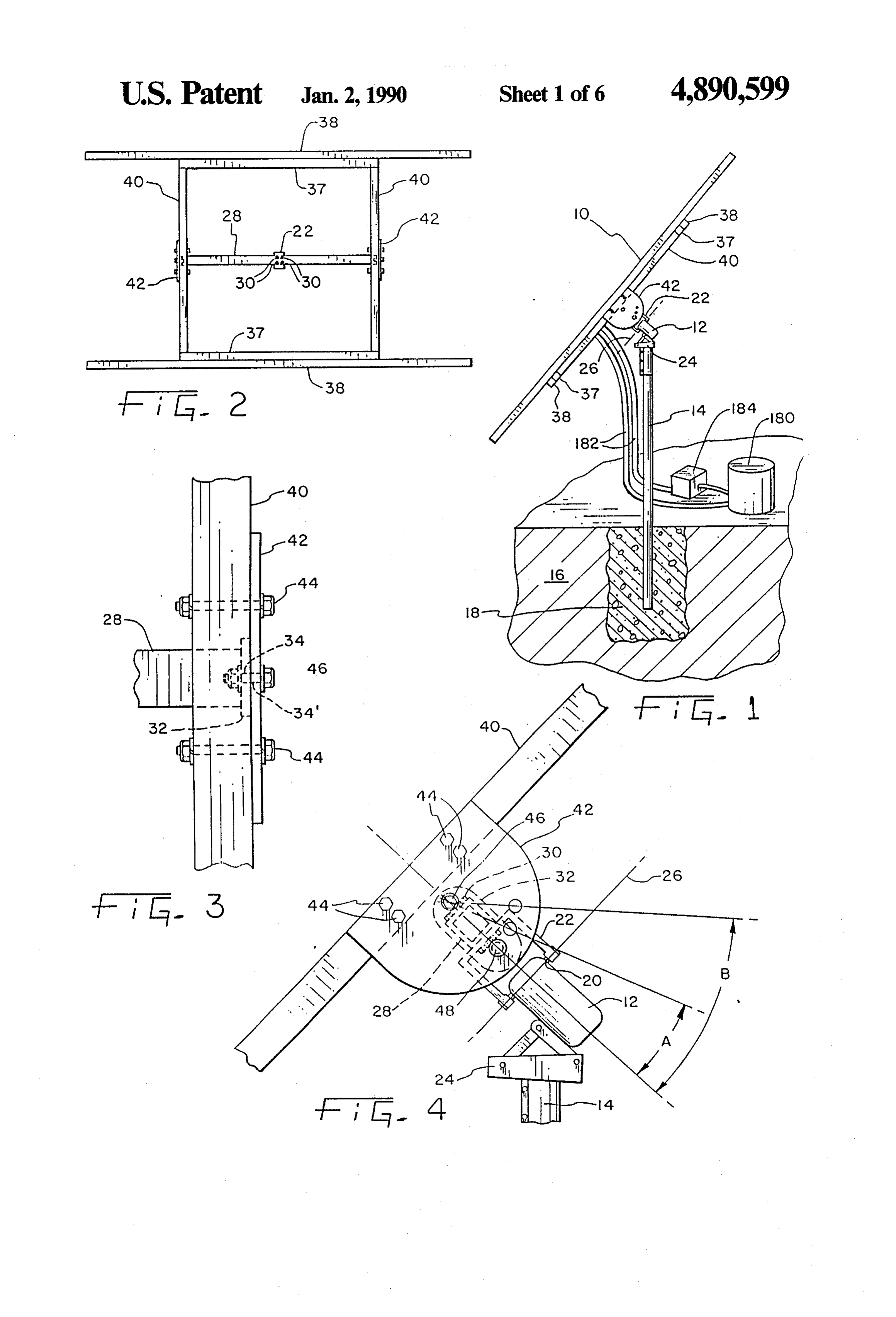
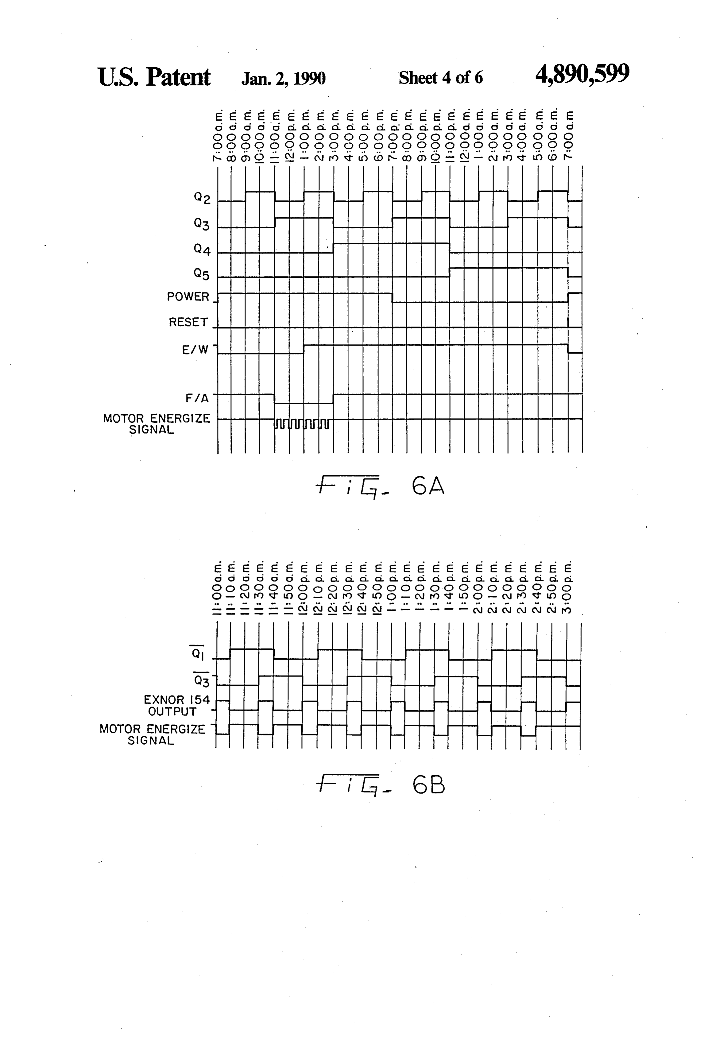
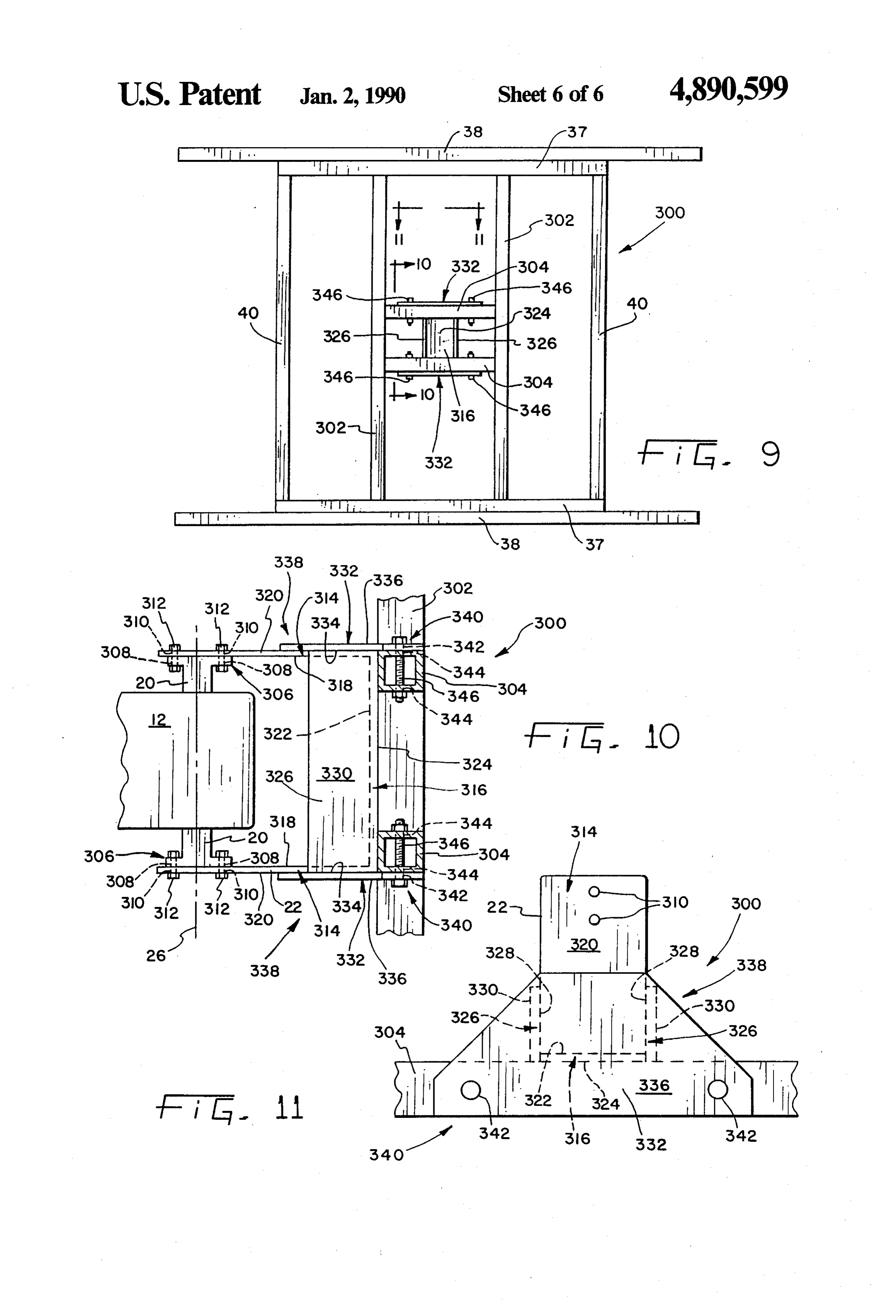
BRIEF DESCRIPTION OF THE DRAWINGS mounting base 24 and so that the axis 26 of motor shaft 20 is situated directionally north/south or, substantially
The above-mentioned and other features and objects parallel to the earth's axis of rotation. Accordingly, of this invention and the manner of attaining them will U-member 22 and solar panel 10, connected to shaft 20, become more apparent and the invention itself will be 5 rotate substantially parallel to the earth's axis of rota better understood by reference to the following descrip tion.
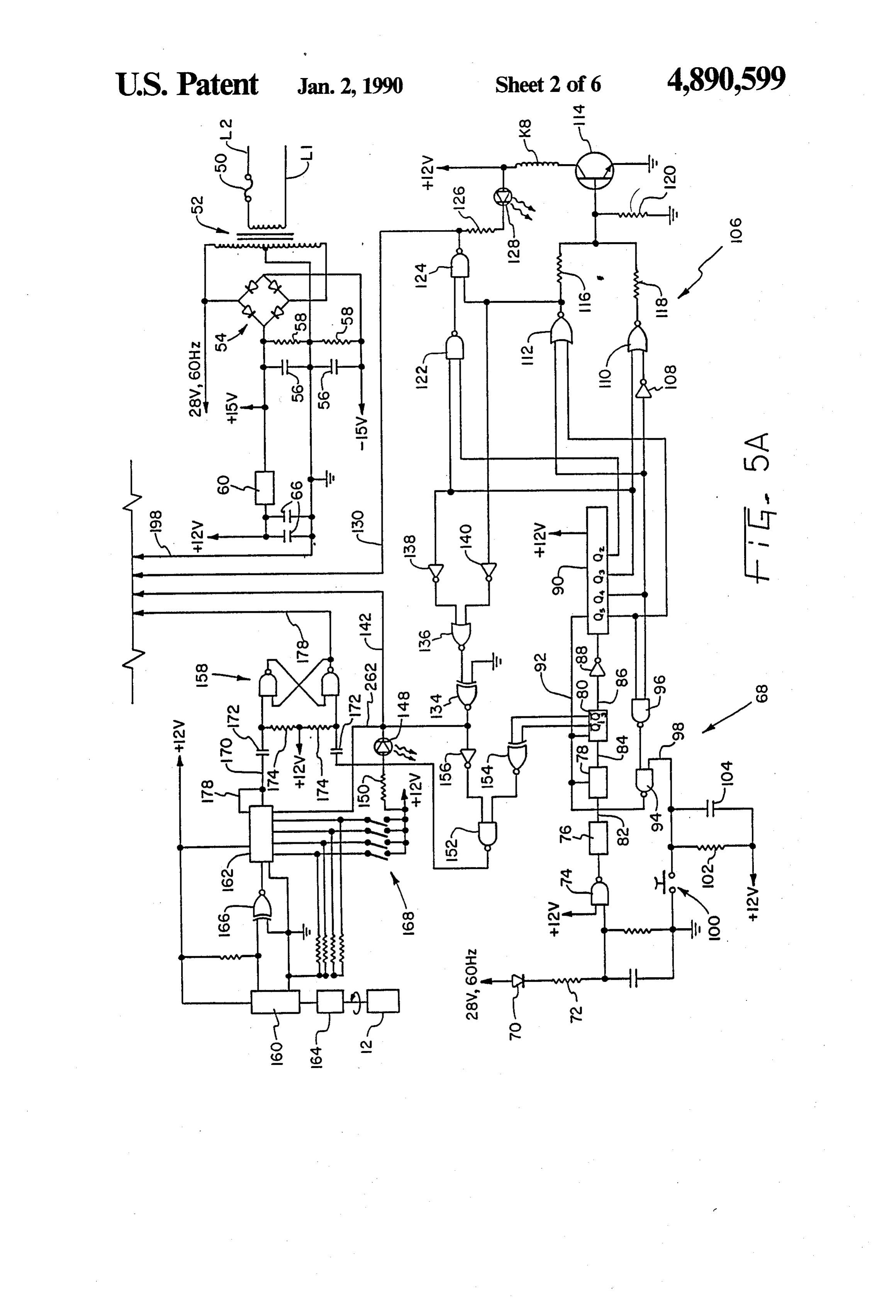
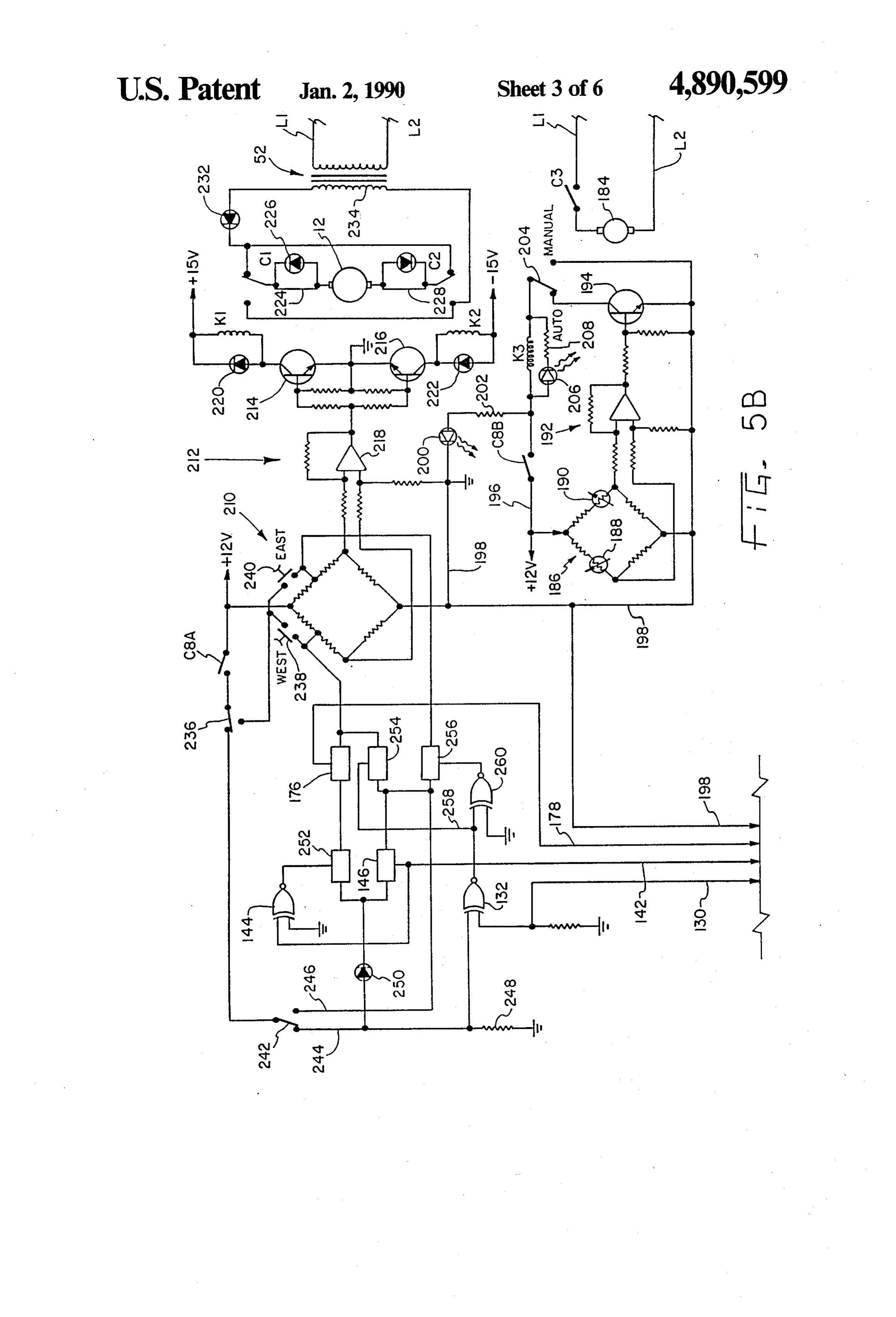
tion of an embodiment of the invention, taken in con As more clearly shown in FIG. 2, square bar member junction with the accompanying drawings wherein: 28 is connected to U-member 22 through the use of FIG. 1 is a side elevational view of a solar energy bolts 30. On each end of square bar member 28, there is collector system utilizing a solar panel, a water pump O connected, by welding or other suitable means, an oval and a water storage tank according to the present inven or flat plate member 32. Each of the oval members 32 tion; has a first pivot hole 34 and a second angle displacement FIG. 2 is a top plan view of the frame of the solar hole 36 for the purpose of pivotally supporting solar collector mount shown in FIG. 1; panel 10 as described hereinbelow. More particularly, FIG.3 is a blown up top plan view of a portion of the 15 solar panel 10 is supported on a frame including hori frame shown in FIG. 1; Zontal beams 37 and 38 and vertical beams 40. Beams 37 FIG. 4 is a blown up side elevational view of the and 40 are connected together to substantially form a collector frame and motor shown in FIG. 1 and show square. Vertical beams 40 are connected to half circle ing more clearly the pivoting of the solar panel to ac plates 42 though the use of bolts 44. Half circle plates commodate the various seasons; 20 42, as shown in FIG. 7, each have a pivot hole 34 corre FIGS. 5a and 5b are an electrical schematic of the sponding with first holes 34 of oval members 32. Half solar tracking control system according to the present circle plates 42 also have three angle displacement holes invention for controlling the pivoting of the solar col 36 for selectively corresponding with the second holes lector shown in FIG. 1 about the pivot axis which is 36 of oval members 32. A pivot shaft or bolt 46 is re situated substantially parallel to the earth's axis of rota 25 ceived through each first hole 34 and pivot hole 34' tion: thereby pivotally holding together oval members 32 FIGS. 6a and 6b are signal diagrams generally depict and half circle plates 42 on each end of square bar mem ing some of the various signals generated by the solar ber 28. Furthermore, selectively received angle dis tracking control system according to the present inven placement shafts or bolts 48 are received through each tion; 30 of the second holes 36 of oval members 32 and one of FIG. 7 is a side elevational view of the frame portion the angle displacement holes 36 of each of the half shown in FIG. 3; circle plates 42, as more clearly shown in FIG. 4. FIG. 8 is a side elevational view of the motor and The angle displacements shafts or bolts 48 are selec oval member shown in FIG. 4; tively received through the oval member second hole FIG. 9 is a top plan view of another embodiment of a 35 36 and any of the displacement holes 36 of the half frame and mounting assembly of the solar collector circle plates 42 so that the frame and solar panel 10, mount shown in FIG. 1; along with plates 42, can be selectively angularly fixed FIG. 10 is a side elevational view of the frame and with respect to oval members 32 and mounting base 24. mounting assembly shown in FIG. 9 taken along line Accordingly, by placing the angle displacement bolts 48 10-10; and, in the various angle displacement holes 36, solar panel FIG. 11 is a top plan view of the frame and mounting 10 can be pivoted so as to more substantially be perpen assembly shown in FIG. 9 taken along line 11-11. dicular to the sun during the various seasons of the year. Corresponding reference characters indicate corre That is, in the north hemisphere, solar panel 10 may be sponding parts throughout the several views of the pivoted to angle B generally during the summer drawings. months, to angle A generally during the spring and fall The exemplifications set out herein illustrate a pre months, and in a position as shown in FIG. 4, generally ferred embodiment of the invention in one form thereof during the winter months. So as to further increase and such exemplifications are not to be construed as efficiency, solar panel 10 is pivoted daily from east to limiting the scope of the disclosure or the scope of the west so as to be substantially perpendicular to the sun invention in any manner. 50 through the use of the solar tracking control system as described hereinbelow.
DETAILED DESCRIPTION OF A SPECIFIC For more rigidly connecting the solar panel or collec
EMBODIMENT
torto withstand winds, snow, etc., a mounting assembly
As shown in the figures, a specific embodiment of the generally designated as 300 in FIGS. 9-11 is provided. present invention includes a solar tracking control sys 55 As shown in FIG. 9, a frame for supporting or mounting tem for use in controlling the position of a pivotable thereon a solar panel or collector is provided and in solar panel connected to a motor by selectively energiz cludes horizontal beams 37 and 38 and vertical outer ing and de-energizing the motor. More specifically, a beams 40 and vertical inner beams 302. All of beams 37, solar panel 10 is provided for collecting the sun's energy 38, 40 and 302 are square bars connected together by and is pivotally mounted to a motor 12, which in turn is welding or other suitable means. The frame further connected to a base or post 14. Post 14 is embedded in includes two square beams 304 connected such as by the ground 16 through the use of concrete 18 or, in welding between vertical inner beams 302. As such, the other suitable fashions. Post 14 is mounted substantially frame is substantially flat and capable of supporting perpendicular to the earth's surface. common solar panels and collectors. As more clearly shown in FIGS. 2-4 and 8, motor 12 65 As described hereinabove, motor 12 mounted on post has a rotating or selectively rotatable shaft 20 upon 14 includes a shaft 20 having an axis of rotation 26. Shaft which there is mounted U-member 22. Motor 12 is 20 is selectively rotated through the use of the solar mounted upon post 14 through the use of a motor tracking control system described hereinbelow. Shaft
Page 11
20 includes flange portions 306 which can be integrally Referring now to FIGS. 5a and 5b, the electronic connected to shaft 20 or connected thereto by other circuitry of the solar tracking control system will be suitable means. Flange portions 306 include holes 308 described. Power is supplied to the solar tracking con which are aligned with U-member holes 310. Bolts.312 trol system from a 120 volt, 60 Hz outlet through two are received through holes 308 and 310 thereby rigidly lines indicated as L1 and L2. A power supply fuse 50 is connecting shaft 20 and flange portion 308 to U-mem provided on L2. Transformer 52 reduces the voltage to ber 22 and, thus, causing U-member 22 to pivot with an appropriate working voltage such as 28 volts. Full shaft 20. wave rectifier 54 is connected to the secondary winding U-member 22 has two legs 314 which are connected 10 of transformer 52 and provides a positive 15 volt and a to one another by middle portion 316. Legs 314 are negative 15 volt output. Power supply capacitors 56 substantially flat and have an inner face 318 and an and power supply resistors 58 are connected between outer face 320. U-member middle portion 316 is also the respective positive 15 volt output and negative 15 substantially flat and has an inner face 322 and an outer volt output of full wave rectifier 54 and the center tap face 324. U-member 22 can be made of, for example, 15 line of transformer 52 acting as ground. A 12-volt regu one-quarter inch thick steel bent to form legs 314 and lator 60 is provided and is connected to the positive middle portion 316 thereby making legs 314 integral 15-volt output of full wave rectifier 54 and the center tap output of transformer 52. Capacitors 66 are con with middle portion 316. In the alternative, legs 314 and nected middle portion 316 can be separate pieces connected between the output of regulator 60 and the cen together by welding or other suitable means. Legs 314 20 ter tap output of transformer 52 and, thus, a 12-volt are situated substantially parallel to one another and regulated
output is provided as shown.
plurality of time dependent signals are created for perpendicular to middle portion 316 and shaft 20. triggering the various electrical components of the solar To reinforce and retain legs 314 substantially perpen tracking control system through the use of a time con dicular to middle portion 316, as substantially flat rein trolled signal programmer means or signal programmer forcing wall 326 is connected by welding or other suit 25 generally designated as 68. To this end, diode 70 is able means to both sides of U-member 22. Reinforcing connected to the above-described 28-volt 60 Hz supply. walls 326 are substantially rectangularly-shaped and are The half-wave rectified output of diode 70 is connected each connected to respective edges of legs 314 and the in series to resistor 72 and to one of the inputs of NAND edge of middle portion 316 on one side thereof. Rein gate forcing walls 326 are made of one-quarter inch thick 30 to the74.regulated
The other input of NAND gate 74 is connected positive 12-volt output of regulator 60.
steel or other suitable material and have an inner face The output of NAND gate 74 is connected in series 328 and an outer face 330. As shown in FIG. 11, inner with dividers 76, 78 and 80, each of which divide by 60. faces 328 of reinforcing walls 326 oppose one another. Dividers 76, 78 and 80 are commonly known as preset To further aid in rigidly connecting U-member 22 to table divide by n counters and are set at divide by 60. the frame, there are provided mounting brackets 332 35 Thus, the output 82 of divider 76 is one cycle per sec connected to U-member 22 and reinforcing walls 326 by ond, the output 84 of divider 78 is one cycle per minute, welding or other suitable means. Mounting brackets 332 and the output 86 of divider 80 is one cycle per hour. are made of one-quarter inch thick steel or other suit The output 86 of divider 80 is connected to invertor 88 able material and have an inner face 334 and an outer which, in turn, is connected to divider 90 having out face 336. Inner face 334 of mounting brackets 332 op puts of Q2 at one cycle per 4 hours, Q3 at one cycle per poses outer face 320 of U-member legs 314. Brackets 8 hours, Q4 at one cycle per 16 hours and, Qs at one 332 have a back frusto-triangular portion 338 and a cycle per 32 hours. Q2, Q3, Q4, and Q5 are shown dia forwardly extending portion 340. Forwardly extending grammatically in FIG. 6. Divider-90 is a seven stage portion 340 extends beyond U-member middle portion binary counter and is set to divide by 24. 316 substantially the same length as the width of square 45 Divider 90 operates on 12 volts and can be reset by beams 304. Mounting bracket forwardly extending por providing a signal on reset line 92. Reset line 92 is con tions 340 have holes 342 which are aligned with square nected to the output of NAND gate 94. One input of beam holes 344. Bracket bolts 346 are received through NAND gate 94 is connected to the output of NAND bracket holes 342 and square beam holes 344 and act to gate 96 which, in turn, is connected to outputs Q4 and rigidly mount square beams 304 along with the frame to 50 Qs of divider 90. The other input of NAND gate 94 is brackets 332 along with U-member 22 and shaft 20. connected to line 98, which is connected to normally Brackets 332 can be attached to square beams 304 by open reset switch 100 leading to ground. Line 98 is also welding or other suitable means, however, the pre connected to an integrator consisting of resistor 102 and ferred method is to use bolts 346 as shown in FIG. 10 so capacitor 104, which are, in turn, connected to a posi as to provide a means by which frame 300 and the solar 55 tive 12 volts. Thus, dividers 78, 80 and 90 can be reset panels or collectors attached thereto can be removed by merely depressing reset switch 100. In the alterna and serviced if necessary. tive, dividers 78, 80 and 90 are reset automatically via As can be appreciated, the above-described mounting the output of NAND gate 94, which is dependent on the assembly for pivotally connecting solar panels or col outputs Q4 and Qs of divider 90.
lectors to the selectively rotatable shaft 20 substantially The solar tracking control system is selectively auto reduces the cost of manufacturing by reducing the matically activated through the use of a power switch quantity of materials needed, utilizing substantially the means generally designated as 106. Power switch means same type of materials throughout and also by reducing 106 includes coil K8, which is connected to and is the time needed to assemble the same. In addition, the adapted to pull closed contacts C8A and C8B. Coil K8 mounting assembly provides a rigid structure capable of 65 is activated through the use of NPN transistor 114 withstanding forces to which the solar panels and col which, in turn, is activated through the use of a power lectors are subjected to, such as those created by winds, signal generating means for generating a power signal in SnOW, etc. response to time dependent signals Q3, Q4, and Qs of
Page 12
divider 90. The power signal for activating coil K8 cally, the output of NAND gate 152 provides the peri through the use of NPN transistor 114 is generated odic motor energizing signals as shown in FIG. 6. That through the use of NOR gates 110 and 112 and invertor is, exnor gate 154 has a first input of Qi and a second 108. The Boolean logic representing the system energiz input Q3 as more clearly shown in FIG. 6b. Exnor gate ing and de-energizing power signal necessary to acti- 5 154 has an output signal also shown in FIG. 6b and is vate NPN transistor 114 is Q3+Q4--Q4Q5. Resistor connected to an input of NAND gate 152. The other 116 is connected in series with the output of NOR gate input of NAND gate 152 is connected to invertor 156 112 and resistor 118 is connected in series with the which, in turn, is connected to the output of exnor gate output of NOR gate 110. Resistor 120 is connected 134 which provides the fixed automatic signal. Accord between the base of NPN transistor 114 and ground. 10 ingly, the output of NAND gate 152 is the motor ener Accordingly, through the use of the power signal gen gizing signal as shown in FIGS. 6a and 6b. It should be erating means, a power signal is produced as shown in noted that the motor energizing signal is connected to a FIG. 6 and coil K8 is energized and contacts C8A and latch means or, more particularly, to a cross coupled C8B are closed over a period of twelve hours. More NAND gate cell generally indicated as 158 for the pur specifically, as shown in FIG. 6, the power signal is 15 pose of setting the same and causing motor 12 to be high between 7:00 a.m. and 7:00 p.m., during which energized moving solar panel 10 westerly as will be time the solar tracking control system is energized. described hereinbelow.
An east/west signal generating means is provided for A means for detecting the degree of pivot of the solar generating an east/west signal in response to time de panel and for resetting cross coupled NAND cell 158 pendent signals Q2 and Q4 and the output of NOR gate 20 by providing a motor de-energizing signal in response 112. East/west signal generating means includes to detecting a preselected degree of pivot and, thereby, NAND gate 122 having a first input of Q2 and a second selectively stopping the westerly movement of solar input of Q3 from divider 90. The output of NAND gate panel 10 is provided. More specifically, motor 12 is 122 is connected to a first input of NAND gate 124. The mechanically coupled to a hall-effect generator 164 second input of NAND gate 124 is connected to the 25 whereby a preset number of electrical signals are cre output of NOR gate 112. The Boolean logic represent ated by every predetermined number of revolutions by ing the east/west signal generating is QQ3-Q495. motor 12. Hall sensor 160 senses the signals created by Accordingly, the output of NAND gate 124 generates generator 164 and is connected to exnor gate 166. The the east/west signal shown in FIG. 6. other input of exnor gate 166 is connected to ground. Resistor 126 and light-emitting diode 128 are con- 30 The output of exnor gate 166 is connected to synchro nected in series between the output of NAND gate 124 nous programmable 4-bit counter 162. It should be and a 12-volt supply. Accordingly, light-emitting diode noted that both hall sensor 160 and counter 162 are 128 lights up and indicates the time during which the connected to a 12-volt supply line and ground as shown. east/west signal is low. It should be noted that the out Synchronous programmable 4-bit counter 162 is pro put of NAND gate 124 or the east/west signal is con- 35 grammed to count down from a 4-bit binary digit nected via line 130 to one of the inputs of exnor gate through the use of switches generally indicated as 168 132. Thus, line 130 and the respective input of exnor connected to a 12-volt source. Thus, when a preselected gate 132 is low from 7:00 a.m. until 1:00 p.m. and high, number of pulses coming from hall sensor 160 and exnor thereafter, as more clearly shown in FIG. 6. gate 166 are counted by counter 162, a reset signal is A fixed automatic signal is also generated through the 40 provided to reset line 170 thereby resetting cross cou use of a fixed automatic signal generating means in pled NAND cell 158. It should be noted that counter response to time dependent signals. Q3 and the output of 162 also resets itself each time it provides a reset signal NOR gate 112. More specifically, the fixed automatic online 170 via line 178. Further, through capacitors 172 signal is provided at the output of exnor gate 134 having and resistors 174, cross coupled NAND gate cell 158 a first input from NOR gate 136 and a second input 45 sets and resets only upon the occurrence of a change of connected to ground. NOR gate 136 has a first input voltage i.e., from high to low or from low to high. More connected to invertor 138 which, in turn, is connected specifically, cross coupled NAND gate cell 158 is set to Q3 of divider 90. The second input of NOR gate 136 when the motor energizing signal goes from high to low is connected to invertor 140 which, in turn, is connected and remains set until line 170 goes from high to low. It to the output of NOR gate 112. Thus, the fixed auto- 50 should also be noted that the output of cross coupled matic signal, which is low from 11:00 a.m. until 3:00 NAND gate cell 158 is connected to solid state relay or p.m. and high at all other times as shown in FIG. 6, is contact 176 via line 178. Counter 162 is also connected applied to line 142 which is connected to one of the to line 142 carrying the fixed automatic signal and is inputs of exnor gate 144 and to solid state relay, more thereby kept in a reset position between 3:00 p.m. and commonly known as a field effect device 146. Thus, a 55 11:00 a.m. when the fixed automatic signal is high. low signal is provided via line 142 to solid state relay or So as to remove the energy collected by solar panel contact 146 and to exnor gate 144 between 11:00 a.m. 10 and store the same, an energy bank such as a water and 3:00 p.m. and a high signal is provided thereto at all storage tank 180 is connected to solar panel 10. In es other times. The Boolean logic representing the fixed sence, storage tank 180 is fluidly connected to solar automatic generator is Q3.Q4Q5. It should be further 60 panel 10 via water lines 182 and a water pump 184 is noted that light-emitting diode 148 and resistor 150 are connected to one of the water lines 182 so as to circulate connected in series between line 142 and a 12-volt sup water between solar panel 10 and water storage tank ply thereby indicating the time of which the fixed auto 180. As shown in FIG. 5b, water pump 184 is electri matic signal is low. cally powered via lines L1 and L2 which are connected A gate means is provided for generating motor ener- 65 thereto and is selectively energized and de-energized gizing signals in response to the fixed automatic signal through the use of contact C3, which is controlled with and the motor energizing signals generated via time coil K3. Coil K3 is itself energized when the tempera dependent signals Q1 and Q3 of divider 80. More specifi ture of solar panel 10 exceeds the temperature of water
Page 13
storage tank 180 by approximately 3 degrees Fahrenheit tially near the end of the desired pivot of solar panel 10 which may be preselected. This temperature difference in the respective westerly or easterly direction and open is sensed by using a bridge 186 having on one leg when solar panel 10 substantially reaches that position thereof storage tank thermistor 188 sensing the water thereby opening a respective limit switch 224 or 228 temperature within storage tank 180 and on the other and causing motor 12 and the pivoting of solar panel 10 leg solar panel thermistor 190 sensing the water temper to stop. Thereafter, due to the open limit switch, motor ature within solar panel 10. The imbalance of bridge 186 12 will operate only when the correct contact C1 or C2 is sensed and amplified through temperature control OP closes, thereby causing motor 12 to pivot solar panel 10 AMP circuit 192 which, in turn, is connected to the base in the opposite direction of that which caused the open of temperature control transistor 194. Transistor 194 10 ing of the limit switch. More specifically, during normal causes coil K3 to be energized thereby pulling contact operation, coil K1 is energized pulling closed contact C3 and, thereby, energizing water pump 184 whenever C1 and causing solar panel 10 to move westerly. When an imbalance in bridge 186 occurs. The resistors used solar panel 10 has been pivoted substantially to the end within bridge 186 and within temperature control OP of the desired angle, west limit switch 224 will open and AMP circuit 192 are size according to general elec 5 motor 12 will stop regardless of whether contact C1 is tronic standards. Further, bridge 186 is connected be closed or open. Thereafter, only the energizing of coil tween 12-volt supply line 196 and line 198 connected to K2 pulling closed contact C2 will allow motor 12 to be the center tap of transformer 52. energized with current flowing through diode 226 and, A contact C8B is connected to 12-volt supply line 196 thereby, causing solar panel 10 to move in the easterly and closes in response to coil K8 thereby providing direction. It should be noted that, in general, the same power to the water pump control circuitry in response operation occurs when the substantially furthest east to the power signal. Light-emitting diode 200 and resis erly pivot is reached, however, in that position, east tor 202 are connected in series between ground and limit switch 228 is opened.
contact C8B thereby providing a visual indication as to Connected in series with contact C8A, there is man when power is provided to the water pump control 25 ual override solar panel control switch 236 shown in its circuitry and the solar tracking control system in gen normally closed position. Switch 236, along with west eral. Coil K3 is connected between contact C8B and manual override switch 238 and east manual override pump manual/automatic switch 204 and light-emitting switch 240 are provided for imbalancing bridge 210 so diode 206 and resistor 208 are connected in parallel with as to make solar panel 10 pivot in the desired direction coil K3. Thus, light-emitting diode 206 provides a visual 30 regardless of the automatic solar tracking control sys indication whenever coil K3 or water pump 184 are tem described hereinabove. That is, west manual over energized. Switch 204 is shown in the automatic posi ride switch 238 is provided for imbalancing bridge 210 tion whereat coil K3. will automatically be energized so as to make solar panel 10 pivot westerly and east upon the occurrence of an imbalance in bridge 186. In manual override switch 240 is provided so as to imbal the alternative, switch 204 may be placed in the manual 35 ance bridge 210 and cause solar panel 10 to pivot east position whereat coil K3 and pump 184 are energized erly.
regardless of any imbalance occurrence in bridge 186. An overload determining means for determining sub The direction of motor 12, which is powered via a stantially when the energy bank or storage tank 180 is 28-volt 60 Hz supply from transformer 52, is controlled substantially full or when solar panel 10 has reached a through the use of motor control bridge 210, motor 40 critical level or temperature and switch means con control OP AMP circuit 212 and coils K1 and K2, nected to the above-described east/west signal generat which are controlled by transistors 214 and 216, respec ing means and the overload determining means for tively. More specifically, each input of OP AMP 218 is overriding the latch means and pivoting the solar panel connected to a respective leg of motor control bridge away from direct sunlight in response to an overload 210. Thus, the output of OP AMP 218 is either zero, 45 determination and in response to the east/west signal is positive or negative, depending on the imbalance of described hereinbelow. More specifically, temperature motor control bridge 210. The output of OP AMP 218 sensitive switch 242 is connected to manual override is connected to the respective bases of NPN transistor solar panel control switch 236 and is normally in the 214 and PNP transistor 216. Accordingly, either coil K1 position shown in FIG. 5b whereat 12-volts is provided or coil K2 can be energized during any particular per 50 to line 244. When the temperature of storage tank 180 is iod of time but not both. Diode 220 is connected in below substantially 140 degrees Fahrenheit or some parallel with coil K1 and diode 222 is connected in other preselected temperature, temperature sensitive parallel with coil K2. The resistors of motor control switch 242 remains in its normal operating position as bridge 210 and motor control OP AMP circuit 212 are shown. Switch 242 is substantially a bimetallic strip sized according to general electrical standards. 55 type thermostat situated so as to sense the temperature Motor 12, on one end thereof, is connected to west of the water within solar panel 10 or storage tank 180 limit switch 224, and diode 226 which are parallel with and to provide an overtemperature control signal when each other and at the other end thereof are, in turn, ever a preselected temperature such as 140 degrees connected to contact C1. At the other end thereof, Fahrenheit is exceeded. In the alternative, temperature motor 12 is connected to east limit switch 228 and diode sensitive switch 242 can be a preset thermosnap disk 230, which are connected parallel to each other and are control switch. Accordingly, whenever the preselected further connected to contact C2 at the other end temperature is exceeded, switch 242 opens and provides thereof. Diode 232 is connected in series with second 12-volts on line 246.
ary winding 234 of transformer 52 thereby providing Line 244 is connected to one of the inputs of exnor rectified current to motor 12. Both contacts C1 and C2 65 gate 132 and to ground via resistor 248. Line 244 is also are shown in their normally closed positions when coils connected to diode 250 which, in turn, is connected to K1 and K2 are not energized. West limit switch 224 and solid state relay 146 and solid state relay 252. It should east limit switch 228 are physically situated substan be noted that solid state relay 146 is controlled via line
Page 14
142 and solid state relay 252 is controlled via the output gate cell 158 and, also, resetting counter 162 via line of exnor gate 144. The output of relay 252 is connected 178. Accordingly, line 178 then goes low thereby open to the input of relay 176 which, as described hereinbe ing solid state relay 252 and closing solid state relay 146 low, is controlled via line 178. The output of relay 176 and, thereby, also de-energizing motor 12 and causing is connected to the west leg of motor control bridge solar panel 10 to stop pivoting. As can be appreciated, 210. The output of solid state relay 146 is connected to the above-described sequence of events whereby the the inputs of solid state relays 254 and 256. It should be cross coupled NAND gate cell 158 is set and reset oc noted that line 246 is also connected to the inputs of curs periodically each half hour as indicated by the solid state relays 254 and 256. Further, solid state relay motor energize signal shown in FIGS. 6a and 6b. In this 254 is controlled via line 258 which is the output of 10 fashion, because the motor energizing signal is time exnor gate 132. Line 258 is also connected to one of the dependent, solar panel 10 is caused to pivot so as to be inputs of exnor gate 260. The other input of exnor gate substantially always perpendicular to the sun. 260 is connected to ground. The output of exnor gate It should be noted that between 7:00 a.m. and 1:00 260 controls solid state relay 256 which, in turn, has an p.m., if temperature sensitive switch 242 is caused to output connected to the east leg of motor control bridge 15 open and provide current to line 246, solar panel 10 will 210. be moved in the westerly direction generally away from The operation of the solar tracking control system direct sunlight due to the low east/west signal. This is will be described hereinbelow. At substantially 7:00 because upon such an occurrence, the output of exnor a.m., the output of NAND gate 94 goes high and gate 132 will be high thereby closing solid state relay thereby resets dividers 78,80, and 90 via reset line 92. 254 and opening relay 256 and, thus, causing current to At that point, the power signal goes high, coil K8 is flow through line 246 and solid state relay 254 to the closed, and contacts C8A and C8B are closed thereby west leg of motor control bridge 210. providing power to the solar tracking control system Between 1:00 p.m. and 7:00 p.m. however, the and indicating the occurrence of this event via light east/west signal on line 130 goes high so that if the emitting diode 200. Simultaneously, the east/west signal 25 temperature sensitive switch 242 opens and makes on line 130 is low and the fixed automatic signal on line contact with line 246, the output of exnor gate 132 is 142 is high. Accordingly, if temperature sensitive low and, thus, the output of exnor gate 260 is high caus switch 242 is in its normal operating position as shown, ing solid state relay 256 to close and solid state relay 254 the output of exnor gate 132 is low and, thus the output to open. Accordingly, current flows through line 246 of exnor gate 260 is high. Further, because the fixed 30 and relay 256 to the east leg of motor control bridge 210 automatic signal is high online 142, the output of exnor and causes solar panel 10 to be pivoted in the easterly gate 144 is low and solid state relay 146 is closed direction away from direct sunlight until east limit thereby allowing current to flow through diode 250, switch 228 is opened.
relay 146 and solid state relay 256 and to the east leg of At 3:00 p.m., the fixed automatic signal goes high bridge 210. Accordingly, coil K2 is energized and 35 and, therefore, no further setting of cross coupled contact C2 is opened thereby causing solar panel 10 to NAND gate cell 158 can occur as also shown by the move easterly until east limit switch 228 is opened. motor energize signal of FIG. 6a. Further, solid state If at 7:00 a.m., after resetting, the temperature sensi relay 146 is closed and solid state relay 252 is open. tive switch is triggered and thus connected to line 246, Further yet, solid state relay 254 is closed because the the output of exnor gate 132 is high thereby closing output of exnor gate 132 is high due to the east/west solid state relay 256 and opening solid state relay 254 signal on line 130 being high and a voltage being pro thereby allowing current to flow through line 246 and vided on line 244. Accordingly, current is allowed to solid state relay 254 to the west leg of motor control travel through diode 250, relays 146 and 254 to the west bridge 210 thereby causing solar panel 10 to move west leg of motor control bridge 210, thereby causing solar erly if not already in the westerly position until west 45 panel 10 to travel the remainder of the way westerly limit switch 224 is opened. until west limit switch 224 is opened. Solar panel 10 will At substantially 11:00 a.m., the fixed automatic signal remain in this most westerly position until the next day goes low as shown in FIG. 6a, and the motor energize at 7:00 a.m. when the system is again automatically reset signal also goes low for a period of 10 minutes as shown and solar panel 10 is caused to move to its full easterly in FIGS. 6a and 6b. Accordingly, cross coupled NAND 50 position. It should be noted that counter 162 is reset via gate cell 158 is set and a high signal is provided on line line 262 upon the fixed automatic signal going high. 178 thereby closing solid state relay 176. Further, be Furthermore, if between 3:00 p.m. and 7:00 p.m., an cause the fixed automatic signal carried on line 142 is overtemperature or overload situation occurs and tem low, solid state relay 146 is open and because the output perature sensitive switch 242 is caused to provide cur of exnor gate 144 is caused to be high, solid state relay 55 rent on line 246, the output of exnor gate 132 becomes 252 is closed. Accordingly, so long as temperature sen low and the output of exnor gate 260 becomes high sitive switch 242 remains in its normal position as thereby allowing current to flow through line 246 and shown, current is allowed to travel through diode 250, relay 256 to the east leg of motor control bridge 210 and closed relays 252 and 176, and to the west leg of motor thereby causing solar panel 10 to be pivoted to its full control bridge 210 thereby energizing coil K1 and clos easterly fixed position until east limit switch 228 is ing contact C1 energizing motor 12 and causing solar opened.
panel 10 to move in the westerly direction. As soon as At 7:00 p.m. the power signal goes low and contacts motor 12 starts to rotate, however, hall sensor 160 gen C8A and C8B are caused to open thereby preventing erates pulses which travel through exnor gate 166 and power from being supplied to the solar tracking control are counted by counter 162. Thereafter, when a prese 65 system until the next day at 7:00 a.m. when the system lected number of pulses coming fromhall sensor 160 are is again reset automatically. As can be appreciated at counted by counter 162, a reset signal is provided on 7:00 a.m. of the next day, the above-described operation reset line 170 thereby resetting cross coupled NAND is repeated.
Page 15
It should further be noted that the above-described of said legs whereby said legs are further kept substan solar tracking control system is originally set by syn tially perpendicular to said middle portion. chronizing the signal programmer with the time of day 11. The mounting assembly of claim 7 further com by depressing reset switch 100 at approximately 7:00 prising a substantially flat mounting bracket having an a.m. Thereafter, as described above, the system auto 5 inner face and an outer face, said mounting bracket matically resets itself at that same time and operates connected to one of said legs with the mounting bracket without any further input from the operator. inner face opposing said one leg outer face, said bracket While the invention has been described as having being connected to said frame.
specific embodiments, it will be understood that it is 12. The mounting assembly of claim 11 wherein a capable of further modifications which are equivalent O portion of said mounting bracket extends beyond said thereto. This application is therefore intended to cover one of said legs and said U-member middle portion, said any variations, uses or adaptations of the invention extending portion of said mounting bracket being con following the general principles thereof and including nected to said frame.
such departures from the present disclosure as come 13. The mounting assembly of claim 12 further com within known or customary practice in the art to which 15 prising a second substantially flat mounting bracket this invention pertains. having an inner face and an outer face, said second What is claimed is: mounting bracket connected to the other of said legs 1. A mounting assembly for pivotally connecting a with the second mounting bracket inner face opposing solar panel or collector to a selectively rotatable shaft, the other of said legs outer face, said bracket being said mounting assembly comprising: 20 connected to said frame.
a frame whereupon the solar panel or collector can be 14. The mounting assembly of claim 13 wherein a mounted;
a U-member having two legs connected to a middle other of of portion said second bracket extends beyond said said legs and said U-member middle portion, portion, said middle portion connected to said said extending portion of said second bracket being
connected to said frame.
wherein said two legs are connected to the selectively rotatable shaft, said U-member, frame and the solar ing15.a The motor mounting assembly of claim 1 further includ connected to the rotatable shaft for selec panel or collector being pivoted about the shaft by tively rotating the same and, a base, said motor and rotating the shaft. rotatable shaft being mounted and supported on said 2. The mounting assembly of claim 1 wherein said 30 base.
U-member legs are substantially parallel to one another 16. A mounting assembly for pivotally connecting a and said middle portion is substantially perpendicular to said legs. solar panel or collector to a selectively rotatable shaft, 3. The mounting assembly of claim 2 further compris said mounting assembly comprising:
ing a substantially flat reinforcing wall connected to 35 a frame whereupon the solar panel or collector can be said middle portion and both of said legs whereby said mounted;
legs are kept substantially perpendicular to said middle a U-member having two substantially flat legs, each portion. of said legs having an inner face and an outer face 4. The mounting assembly of claim 3 further compris and being connected to a middle flat portion hav ing a second substantially flat reinforcing wall con ing an inner face and an outerface and wherein said nected to the said middle portion and both of said legs middle portion is substantially perpendicular to whereby said legs are kept substantially perpendicular both of said legs;
to said middle portion. two substantially flat mounting brackets each having 5. The mounting assembly of claim 1 further compris an inner face and an outer face, one of said mount ing a mounting bracket connected to one of said legs 45 ing brackets connected to one of said legs with the and to said frame for rigidly connecting said frame to mounting bracket inner face opposing said one leg said U-member. outer face and being connected to said frame, said 6. The mounting assembly of claim 5 further compris other mounting bracket connected to the other of ing a second mounting bracket connected to the other said legs with the mounting bracket inner face of said legs and to said frame for rigidly connecting said 50 opposing said other leg outer face and being con frame to said U-member. nected to the frame;
7. The mounting assembly of claim 1 wherein said two substantially flat reinforcing walls, each of said legs are substantially flat, each having an inner face and walls connected to said middle portion and both of an outer face, said middle portion being flat and having said legs whereby said legs are kept substantially an inner face and an outer face and wherein said middle 55 perpendicular to said middle portion; and, portion is substantially perpendicular to both of said wherein said two legs are connected to the selectively legs. rotatable shaft, said U-member, frame and the solar 8. The mounting assembly of claim 7 wherein said panel or collector being pivoted about the shaft by middle portion is integrally connected to each of said rotating the shaft.
legs. 17. The mounting assembly of claim 16 wherein said 9. The mounting assembly of claim 7 further compris mounting brackets extend beyond said legs and said ing a substantially flat reinforcing wall connected to U-member middle portion and wherein said extending said middle portion and both of said legs whereby said part of said brackets are connected to said frame. legs are kept substantially perpendicular to said middle 18. The mounting assembly of claim 17 further in portion. 65 cluding a motor connected to the rotatable shaft for 10. The mounting assembly of claim 9 further con selectively rotating the same and, a base, said motor.and prising a second substantially flat reinforcing wall con rotatable shaft being mounted and supported on said nected to the other side of said middle portion and both base.
Page 16
19. A mounting assembly for pivotally connecting a frame and first plate can pivot with respect to said solar panel or collector to a base, said mounting assem second plate and the base; bly comprising: an angle displacement shaft selectively received a frame whereupon the solar panel or collector can be through said second plate angle displacement hole mounted; and any one of said first plate angle displacement a first plate connected to said frame, said plate having holes whereby said frame and first plate can be a pivot hole and a plurality of angle displacement selectively angularly fixed with respect to said holes each being equidistant from said pivot hole; second plate and the base;
a second plate connected to the base and situated 10 a U-member having two legs, said second plate being connected to said U-member; and, substantially parallel to said first plate, said second a selectively rotatable shaft situated substantially plate having a pivot hole and an angle displacement perpendicular to the axis of rotation between said hole being situated substantially the same distance first and second plates and being pivotally mounted apart from said second plate pivot hole as said on the base, said two legs connected to the selec distance between said pivot and displacement holes 15 tively rotatable shaft whereby the frame is pivoted of said first plate; about the selectively rotatable shaft axis of rotation a pivot shaft received through said first plate pivot by pivoting saidk rotatable
shaft.
hole and said second plate pivot hole whereby said
Provenance
- Collection
- Cited prior art
- Original PDF
- patentimages.storage.googleapis.com →
- Filed
- 1988-05-11
- Pages
- 16
- Method
- pdftotext (the PDF's own text layer) + pdftoppm 300dpi page scans
- Source
- Google Patents bibliographic record
- Granted
- 1990-01-02
- Inventors
- Glenn E. Eiden
- Transcribed from
- patentimages.storage.googleapis.com →