patent · US2825260
Optical image forming devices
4 March 1958
Page 1
Drawing sheet — no readable text.
Page 2
United States Patent Office 2,825,260 Patented Mar. 4, 1958
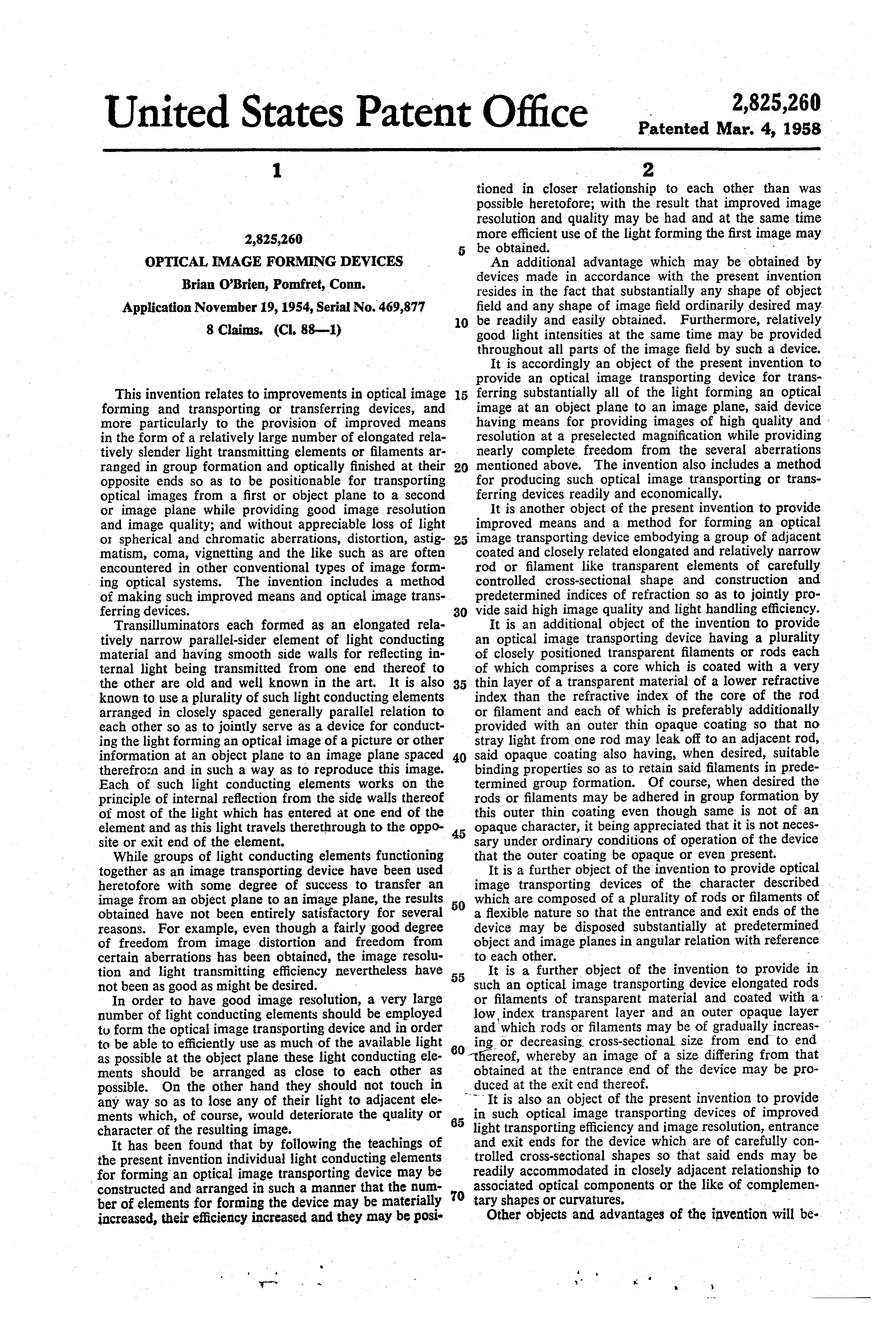
tioned in closer relationship to each other than was possible heretofore; with the result that improved image resolution and quality may be had and at the same time 2,825,260 more efficient use of the light forming the first image may be obtained.
OPTTCAL MAGE FORMING DEVICES An additional advantage which may be obtained by Brian O'Brien, Pomfret, Conn. devices made in accordance with the present invention resides in the fact that substantially any shape of object
Application November 19, 1954, Serial No. 469,877 field and any shape of image field ordinarily desired may. O be readily and easily obtained. Furthermore, relatively 8 Claims. (Cl, 88-1) good light intensities at the same time may be provided throughout all parts of the image field by such a device.
It is accordingly an object of the present invention to provide an optical image transporting device for trans
This invention relates to improvements in optical image 5 ferring substantially all of the light forming an optical forming and transporting or transferring devices, and image at an object plane to an image plane, said device more particularly to the provision of improved means having means for providing images of high quality and in the form of a relatively large number of elongated rela resolution at a preselected magnification while providing tively slenderlight transmitting elements or filaments ar nearly complete freedom from the several aberrations ranged in group formation and optically finished at their 20 mentioned above. The invention also includes a method opposite ends so as to be positionable for transporting for producing such optical image transporting or trans optical images from a first or object plane to a second ferring devices readily and economically. or image plane while providing good image resolution It is another object of the present invention to provide and image quality; and without appreciable loss of light improved means and a method for forming an optical or spherical and chromatic aberrations, distortion, astig 25 image transporting device embodying a group of adjacent matism, coma, vignetting and the like such as are often coated and closely related elongated and relatively narrow encountered in other conventional types of image form rod or filament like transparent elements of carefully ing optical systems. The invention includes a method controlled cross-sectional shape and construction and of making such improved means and optical image trans predetermined indices of refraction so as to jointiy pro ferring devices. 30 vide said high image quality and light handling efficiency. Transilluminators each formed as an elongated rela It is an additional object of the invention to provide tively narrow parallel-sider element of light conducting an optical image transporting device having a plurality material and having smooth side walls for reflecting in of closely positioned transparent filaments or rods each ternal light being transmitted from one end thereof to of which comprises a core which is coated with a very the other are old and well known in the art. It is also 35 thin layer of a transparent material of a lower refractive known to use a plurality of such light conducting elements index than the refractive index of the core of the rod arranged in closely spaced generally parallel relation to or filament and each of which is preferably additionally each other so as to jointly serve as a device for conduct provided with an outer thin opaque coating so that no ing the light forming an optical image of a picture orother stray light fromone rod may leak off to an adiacentrod, information at an object planeto animage plane spaced 40 said opaque coating also having, when desired, suitable therefrom and in such a way as to reproduce this image. binding properties so as to retain said filaments in prede Each of such light conducting elements works on the termined group formation. Of course, when desired the principle of internal reflection from the side walls thereof rods or filaments may be adhered in group formation by of most of the light which has entered at one end of the this outer thin coating even though same is not of an element and as this light travels therethrough to the oppo 45 opaque character, it being appreciated that it is not neces site or exit end of the element. sary under ordinary conditions of operation of the device While groups of light conducting elements functioning that the outer coating be opaque or even present. together as an image transporting device have been used It is a further object of the invention to provide optical heretofore with some degree of success to transfer an image transporting devices of the character described image from an object plane to animageplane, the results which are composed of a plurality of rods or filaments of obtained have not been entirely satisfactory for several 50 a flexible nature so that the entrance and exit ends of the reasons. For example, even though a fairly good degree device may be disposed substantially at predetermined of freedom from image distortion and freedom from object and imageplanes in angular relation with referenc certain aberrations has been obtained, the image resolu to each other.
tion and light transmitting efficiency nevertheless have 55 It is a further object of the invention to provide in not been asgood as might be desired. such an optical image transporting device elongated rods In order to have good image resolution, a very large or filaments of transparent material and coated with a number of light conducting elements should be employed low, index transparent layer and an outer opaque layer tu form the optical image transporting device and in order and which rods or filaments may be of gradually increas to be ableto efficiently use as much of the available light 60 ing or decreasing. cross-sectional size from end to end as possible at the object plane these light conducting ele thereof, whereby an image of a size differing from that ments should be arranged as close to each other as obtained at the entrance end of the device may be pro possible. On the other hand they should not touch in duced at the exit end thereof.
any way so as to lose any of their light to adiacent ele It is also an object of the present invention to provide ments which, of course, would deteriorate the quality or 65 in such optical image transporting devices of improved character of the resulting image. light transporting efficiency and image resolution, entrance It has been found that by following the teachings of and exit ends for the device which are of carefully con the present invention individual light conducting elements i trolled cross-sectional shapes so that said ends may be readily accommodated in closely adiacent relationship to for forming an optical image transporting device may be associated constructed and arranged in such a manner that the num 70 optical components or the like of complemen ber of elements for forming the device may be materially tary shapes or curvatures.
increased, their efficiency increased and they may be posi Other objects and advantages of the invention will be
Page 3
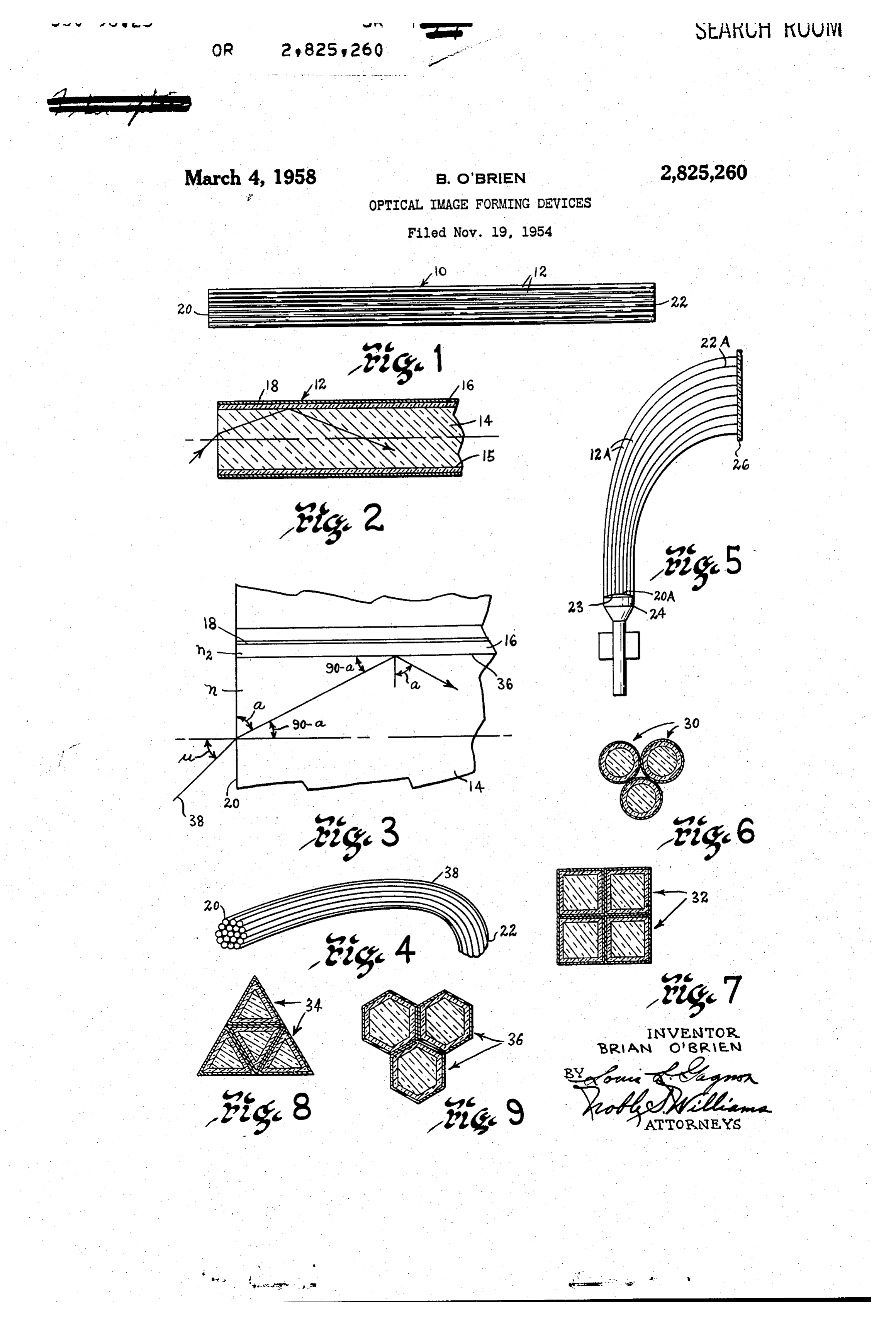
come apparent from the detailed description which fol cally finished or polished so as to readily accept light lows when taken in conjunction with the accompanying incident thereon and being provided by suitable means drawings in which: adiacent one end thereof so as to readily emit this light Fig. 1 is a side elevational view of an optical image to suitable means adjacent the opposite end thereof. transporting device embodying the present invention; As shown in Fig. 4 the entrance end 20 of such a Fig. 2 is an enlarged longitudinal sectional view of bundle of rods may be differently oriented relative to the a single rod or filament embodying the present invention exit end 22 of the same bundle and as will be readily and serving to form with a plurality of elements of similar apparent from Fig. 5, furthermore, the entrance end 20 construction the device of Fig. 1; M of such an optical image transporting device may have Fig. 3 is a diagrammatic sketch for use in readily ob O its surface concavely shaped so as to fit closely adjacent taining a clearunderstanding of the invention; image providing means as, for example in the present Fig. 4 is a perspective view of an optical image trans instance, the curved fluorescent screen 23 of a cathode porting device showing the rods or filaments thereof bent ray tube indicated at 24. In this connection it will be so as to provide differently oriented optically finished noted that while one end of the image transporting device entrance and exit ends at opposite ends of the device; 5 may be purposely controlled in shape to provide a de Fig. 5 is an optical image transporting device some sired curvature of field at the entrance end 20A thereof, What like that shown in Fig. 1 but formed of rods or fila it is possible to provide at the opposite or exit end 22A ments of gradually increasing cross-sectional sizes through thereof an entirely different shape or curvature which out their respective lengths and so finished at the op depends solely upon the purpose for which that end of posite ends thereof as to provide or accommodate dif the device is intended. In the present instance, a sub ferently oriented and differently shaped object and image stantially flat image ?ield adjacent a translucent viewing fields therefor; and screen 26 is desired.
Figs. 6, 7, 8 and 9 are rods or filaments of different As stated above, the cross-sectional size of the in cross-sectional shapes which will provide devices having dividual rods or filaments of a bundle constituting an efficient lightgathering and light transmitting characteris 25 optical image transporting device, will depend largely tiCS. upon the purpose for which same is intended. In Fig. 5 Referring more particularly to the drawings wherein for example, it may be desirable for good image resolu like characters of reference designate like parts through tion to have a very large number of rods or filaments out the several views, an optical image transporting device adjacent the screen 23 of the cathode ray tube, so that embodying the invention is shown at 10 in Fig. 1 and 0 each individual rod or filament thereof Will transport comprises a relatively large number of relatively long light from a relatively small unit area of the screen 23 thin rods or filaments 12 arranged in closely adiacent to a corresponding unit area of the viewing screen 26. generally parallel side-by-side relation to one another so In the particular use of the image transporting device of as to forn a group or bundle. Each of these rods or Fig. 5, wherein a predetermined degree of magnification filaments of the group, as shown in Fig. 2, in turn com 35 of final image is desired, it is possible to provide a prises a main body portion or core 14 formed of a trans gradual increase in cross-sectional size ortaper to the parent or:light conducting material and having smooth individual rods or filaments 12A considered from en side Walls so as to act as mirror-like surfaces providing trance to exit ends thereof, and this may be done in such internal reflection for light which has entered at one end a fashion that the illuminated elemental areas of equal of the rods or filaments and is traveling towards the op 40 size of the cathode ray tube will be in turn reproduced posite ends thereof. A first relatively thin coating ori by corresponding elemental area of equal but larger size layer 16 of transparent or light conducting material is upon the viewing screen 26 notwithstanding the fact that carried by and surrounds the core 14, and about this the entrance and exit ends are differently oriented or first coating it is desirable to provide a second relatively the fact that some parts of the screen 26 are nearer to thin layer or coating of an opaque and preferably light the tube face 23 than are other parts thereof. absorbing material 18. ' It should be appreciated that in such an arrangement The transparent material forming the core 14 inten as shown in Fig. 5, even though the entrance end of tionally has a higher index of refraction than the trans such a device is shaped to closely accommodate the size parent material of the first coating 16 so that the internal and shape of the tube 24, and the exit end thereof is reflection mentioned above of the light traveling from 50 differently shaped from the entrance end thereof, and end to end through the core will occurat the side wall the rods 12A of the device are curved so as to have the surfaces of the core, or in other words at the interface general plane of the viewing screen 26 differently 15 between the core 14 and layer 16, without entering oriented relative to the general plane of the screen of orbeing absorbed by the coating 16.. The outer opaque the cathode ray tube, and of different transverse dimen coating 18 serves a double function in that it insures 55 sions at different sections thereof, nevertheless the image that should any light leak out from the core 14 into the being reproduced upon the viewing screen 26 will be material forming the coating 16 due to imperfect inter relatively free from distortion, as well as aberrations facial surface conditions between these two parts this such as spherical and chromatic aberrations, coma, as light will not thereafter be allowed to reach an adiacent tigmatism and the like. Furthermore, the light intensi rod or filament through anypoint of contact therebetween. O ties over all parts of the image being provided upon the Of course, such a condition, if not prevented, might cause screen 26 will compare favorably with the intensities as a deterioration of quality of the light being conducted by provided initially at corresponding locations on the screen the latterrod or filament. The other function of opaque of the associated cathode ray tube. coating 18 is to serve as a binding material during the ?t has been mentioned previously that it is desirable formation of the group or bundle, whereby the plurality 5 to utilize as much of the available light at the entrance of rod or filament like members 12 will be firmly held in end of the device as possible. Accordingly there are theirinitial intended relationship to each other. shown at Figs. 6, 7, 8 and 9 cross sectional shapes of The size of each group or bundle of light conducting filaments in adiacent relation to each other which may rods or filaments will, obviousy, depend upon the purpose be utilized satisfactorily when forming the rods or fila for Which the optical image transporting device is in 0 ments of the improved type desired. While the rods or tended and of course the cross-sectional size of the rods filaments 30 of Fig. 6 are shown as of circular form and or filaments thereof will in turn depend upon the degree arranged closely adjacent one another, most of the light of resolution desired in the image being transported there impinging upon the ends of the cores thereof will enter by. The opposite ends, or entrance and exit ends 20 these rods and be conducted thereby even though a and 22 respectively, of each bundle are preferably opti 75 small percentage thereof may be lost at opaque and
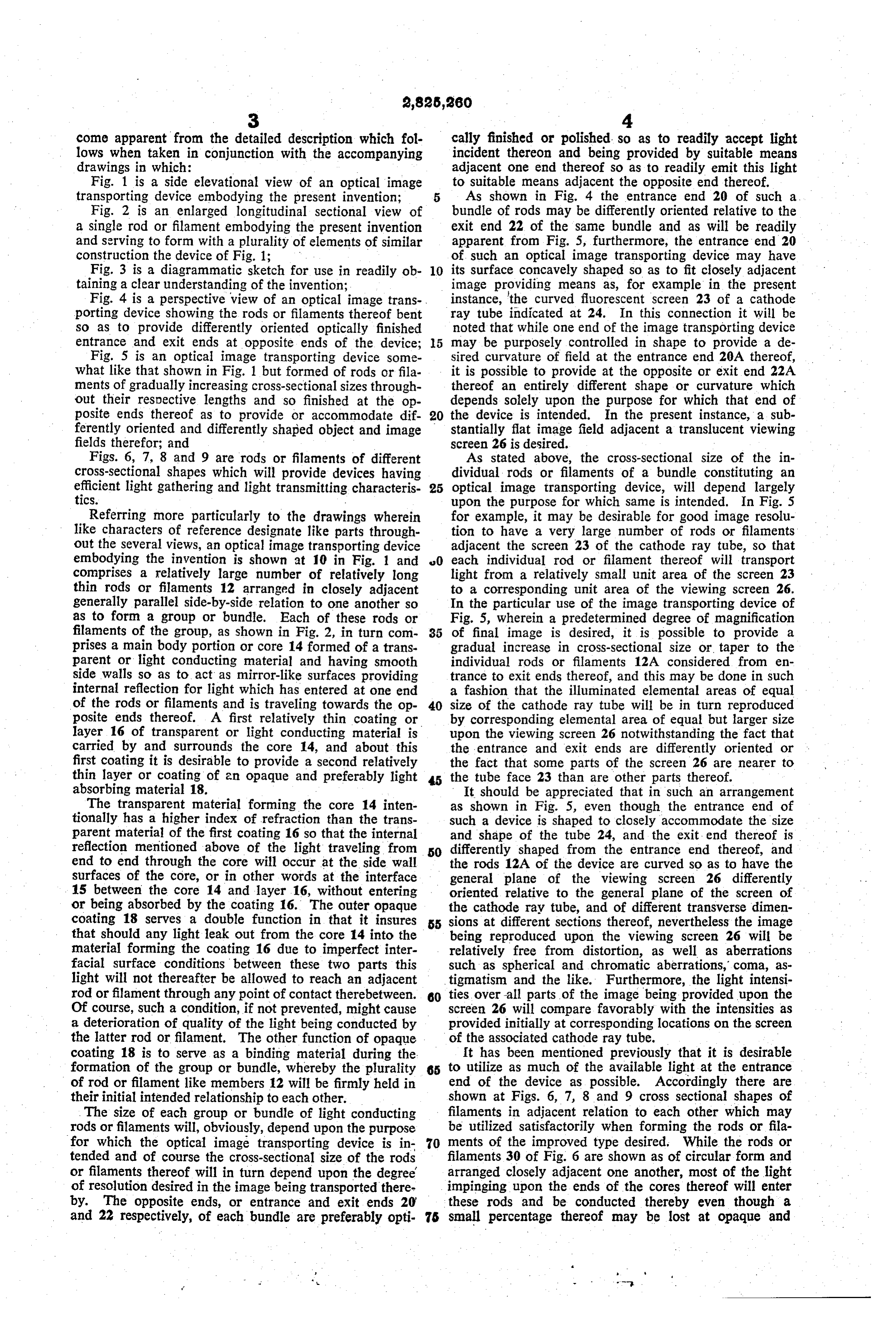
Page 4
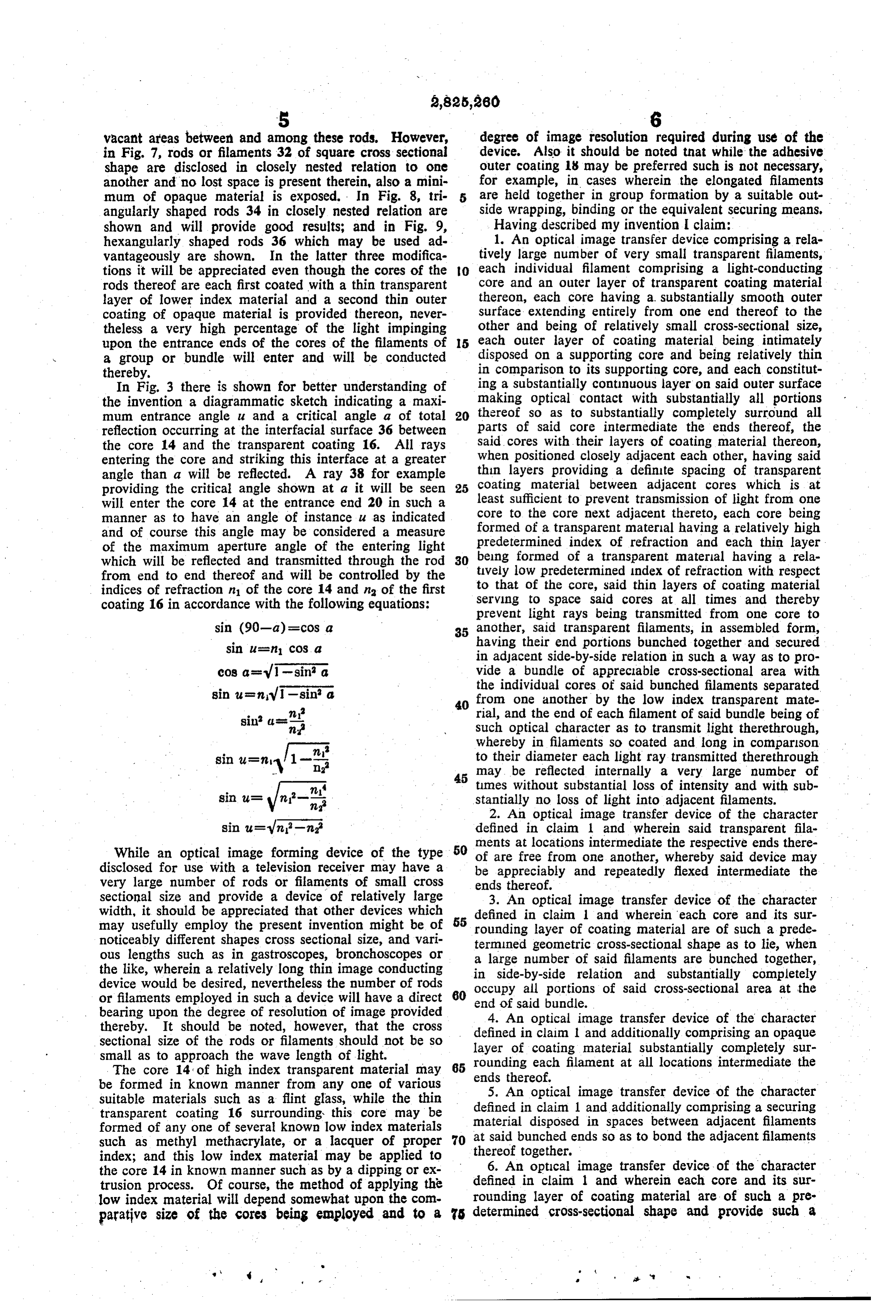
vacant areas between and among these rods. However, degree of image resolution required during use of the in Fig. 7, rods or filaments 32 of square cross sectional device. Also it should be noted that while the adhesive shape are disclosed in closely nested relation to one outer coating 18 may be preferred such is not necessary, another and no lost space is present therein, also a mini for example, in cases wherein the elongated filaments mum of opaque material is exposed. In Fig. 8, tri are held together in group formation by a suitable out angularly shaped rods 34 in closely nested relation are side Wrapping, binding or the equivalent securing means. shown and will provide good resuits; and in Fig. 9, Having described my invention I clain: hexangularly shaped rods 36 which may be used ad 1. An optical image transfer device comprising a rela vantageously are shown. In the latter three modifica tively large number of very small transparent filaments, tions it will be appreciated even though the cores of the O each individual filament comprising a light-conducting rods thereof are each first coated with a thin transparent core and an outer layer of transparent coating material layer of lower index material and a second thin outer thereon, each core having a. substantially Smooth outer coating of opaque material is provided thereon, never surface extending entirely from one end thereof to the theless a very high percentage of the light impinging other and being of relatively small cross-sectional size, upon the entrance ends of the cores of the filaments of 5 each outer layer of coating material being intimately a group or bundle will enter and will be conducted disposed on a supporting core and being relatively thin thereby, in comparison to its supporting core, and each constitut In Fig. 3 there is shown for better understanding of ing a substantially continuous layer on said outer surface the invention a diagrammatic sketch indicating a maxi making optical contact with substantially all portions mum entrance angle u and a critical angle a of total thereof so as to substantially completely surround all reflection occurring at the interfacial surface 36 between parts of said core intermediate the ends thereof, the the core 14 and the transparent coating 16. All rays said cores with their layers of coating material thereon, entering the core and striking this interface at a greater When positioned closely adjacent each other, having said angle than a will be reflected. A ray 38 for example thin layers providing a definite spacing of transparent coating material between adjacent cores which is at providing the critical angle shown at a it will be seen 25 least will enter the core 14 at the entrance end 20 in such a sufficient to prevent transmission of light from one manner as to have an angle of instance u as indicated core to the core next adjacent thereto, each core being and of course this angle may be considered a measure formed of a transparent material having a relatively high of the maximum aperture angle of the entering light predetermined index of refraction and each thin layer which will be reflected and transmitted through the rod beng formed of a transparent material having a rela from end to end thereof and will be controlled by the tvely low predetermined Index of refraction with respect indices of refraction n of the core 14 and na of the first to that of the core, said thin layers of coating material coating 16 in accordance with the following equations: serving to space said cores at all times and thereby prevent light rays being transmitted from one core to sin (90-a) =cosa 35 another, Said transparent filaments, in assembled form, sin u=n cos a having their end portions bunched together and secured in adacent side-by-side relation in such a way as to pro cos a=V1-sin a vide a bundle of appreciable cross-sectional area with sin u= nv sinº a the individual cores of said bunched filaments separated 40 from one another by the low index transparent mate n rial, and the end of each filament of said bundle being of m Such optical character as to transmit light therethrough, whereby in filaments so coated and long in comparson sin u=ny 1-º to their diameter each light raytransmitted therethrough 45 may be reflected internally a very large number of times Without substantial loss of intensity and with sub sin u= stantially no loss of light into adjacent filaments. 2. An optical image transfer device of the character defined in claim 1 and wherein said transparent fila ments at locations intermediate the respective ends there
While an optical image forming device of the type 50 of are free from one another, whereby said device may disclosed for use with a television receiver may have a be appreciably and repeatedly flexed intermediate the very large number of rods or filaments of small cross ends thereof.
sectional size and provide a device of relatively large 3. An optical image transfer device of the character width, it should be appreciated that other devices which defined in claim l' and wherein each core and its sur may usefully employ the present invention might be of 55 rounding layer of coating material are of such a prede noticeably different shapes cross sectional size, and vari termined geometric cross-sectional shape as to lie, when ous lengths such as in gastroscopes, bronchoscopes or a large number of said filaments are bunched together, the like, wherein a relatively long thin image conducting in side-by-side relation and substantially completely device would be desired, nevertheless the number of rods 60 occupy all portions of said cross-sectional area at the or filaments employed in such a device will have a direct end of said bundle. v bearing upon the degree of resolution of image provided 4. An optical image transfer device of the character thereby. It should be noted, however, that the cross defined in claim 1 and additionally comprising an opaque sectional size of the rods or filaments should not be so layer of coating material substantially completely sur small as to approach the wave length of light. rounding each filament at al locations intermediate the The core 14 of high index transparent material may 65 ends thereof.
be formed in known manner from any one of various 5. An optical image transfer device of the character suitable materials such as a fint glass, while the thin defined in claim 1 and additionally comprising a securing transparent coating 16 surrounding this core may be formed of any one of several known low index materials material disposed in spaces between adiacent filaments such as methyl methacrylate, or a lacquer of proper 70 at said bunched endsso as to bond the adiacent filaments index; and this low index material may be applied to thereof together. M the core 14 in known manner such as by a dipping or ex 6. An optical image transfer device of the character trusion process. Of course, the method of applying the defined in claim 1 and wherein each core and its sur rounding layer of coating material are of Such a pre low index material will depend somewhat upon the com parative size of the cores being employed and to a 5 determined cross-sectional shape and provide Such a
Page 5
geometric pattern, when a large number of said filaments 8. An optical image transfer device comprising a rel are bunched together in side-by-side contacting relation, atively large number of very small transparent filaments, as to provide a distribution of small unoccupied spaces each individual filament comprising a light-conducting dispersed among said filaments at the cross-sectional end core and an outer layer of transparent coating material area of said bundle. - eXtending throughout portions thereof, each core hava 7. An optical image transfer device comprising a rel ing a substantially smooth outer surface extending en atively large number of very small transparent light tirely from one end thereof to the other and being of rel conducting cores, each core having a substantially smooth atively small cross-sectional size, each outer layer of i outer Surface extending entirely from one end thereof to coating material being intimately disposed on said por the other and being of relatively small cross-sectional O tions of said supporting core and being relatively thin size, means comprising relatively thin transparent low in comparison to its supporting core, and each consti index material between portions of each of said cores for tuting a substantially continuous layer on said outer sur initially positively retaining said portions of said cores face of said portions and making optical contact with in spaced relation with each other and enabling said substantially all said portionsso as to substantially com cores to be bunched together throughout the length of 15 pletely surround all parts thereof, the said cores with said portions to provide a bundle of appreciable cross their layers of coating material thereon, when positioned sectional area, said individual cores of said bunch being closely adjacent each other, having said thin layers pro separated by said low index spacing material, said low viding a definite spacing of transparent coating material index spacing material in the final assembled device be between adjacenti cores which is at least sufficient to ing intimately disposed on the adiacent supporting cores 20 prevent transmission of light from one core to the core and being relatively thin in comparison to said support next adiacent thereto, each core being formed of a trans ing cores, and each constituting a substantially continu parent material having a relatively high predetermined ous layer on the outer surfaces of said portions and mak index of refraction and each thin layer being formed of ing optical contact with substantially all of said portions a transparent material having a relatively low predeter so as to substantially completely surround said portions 25 mined index of refraction with respect to that of the core, of said cores, the said cores with said spacing material said thin layers of coating material serving to space therebetween, when positioned closely adjacent each said cores at all times, said transparent filaments, in as other, providing a definite spacing of transparent material sembled form, having their end portions bunched together between adiacent cores which is at least sufficient to pre and secured in adiacent side-by-side relation in such a vent transmission of light from one core to the core next 30 way as to provide a bundle of appreciable cross-sectional adiacent thereto, each core being formed of a transpar area with the individual cores of said bunched filaments ent material having a relatively high predetermined in separated from one anotherby the low index transpar dex of refraction with respect to that of said low index ent material, and the end of each filament of said bundle spacing material, said low index material serving to in being of Such optical character as to transmit light there sure spacing of said portions of said cores at al times 35 through, whereby in filaments so coated and long in com and thereby prevent light rays being transmitted from parison to their diameter each light ray transmitted one core to another, said cores and spacing material, in therethrough may be reflected internally a very large assembled form, having their end portions bunched to number of times without substantial loss of intensity and gether and secured in adjacent side-by-side relation in with substantially no loss of light into adjacent filaments Such a Way as to provide a bundle of appreciable cross 40 throughout said coated portions.
sectional area with the individual cores thereof separated from one anotherby the low index transparent material, References Cited in the file of this patent and the end of each core of said bundle being of such UNITED STATES PATENTs M optical character as to transmit light therethrough, said 1,642, 187 Young ---------------- Sept. 13, 1927 cores being long in comparison to their diameter and 1751.584 - Hansell---------------- Mar. 25, 1930 said low index material between said cores being such 1,848,814 Allen ----- - = = a - re - --- Mar. 8, 1932 that light rays transmitted therethrough may be reflected 2,128,246 Hardesty-------------- Aug. 30, 1938 internally a very large number of times without substan 2,354591 - Goldsmith ------------- July 25, 1944 tialloss of intensity and with substantially no loss of light into adiacent filaments throughout said portions.
Provenance
- Collection
- Cited prior art
- Original PDF
- patentimages.storage.googleapis.com →
- Filed
- 1954-11-19
- Pages
- 5
- Method
- pdftotext (the PDF's own text layer) + pdftoppm 300dpi page scans
- Source
- Google Patents bibliographic record
- Granted
- 1958-03-04
- Inventors
- O'brien Brian
- Transcribed from
- patentimages.storage.googleapis.com →