patent · US9942
Tbip-hammer
16 August 1853
Page 1
Drawing sheet — no readable text.
Page 2
UNITED STATES PATENT OFFICE.
WILLIAM WAN ANDEN, OF POUGHIKEEPSIE, NEW YORK.
Specification of Letters Patent No. 9,942, dated August 16, 1858.
To all whom, it may concern: the upper part of the lever passing under the Be it known that I, WILLIAM WAN ANDEN, set screw, (b).
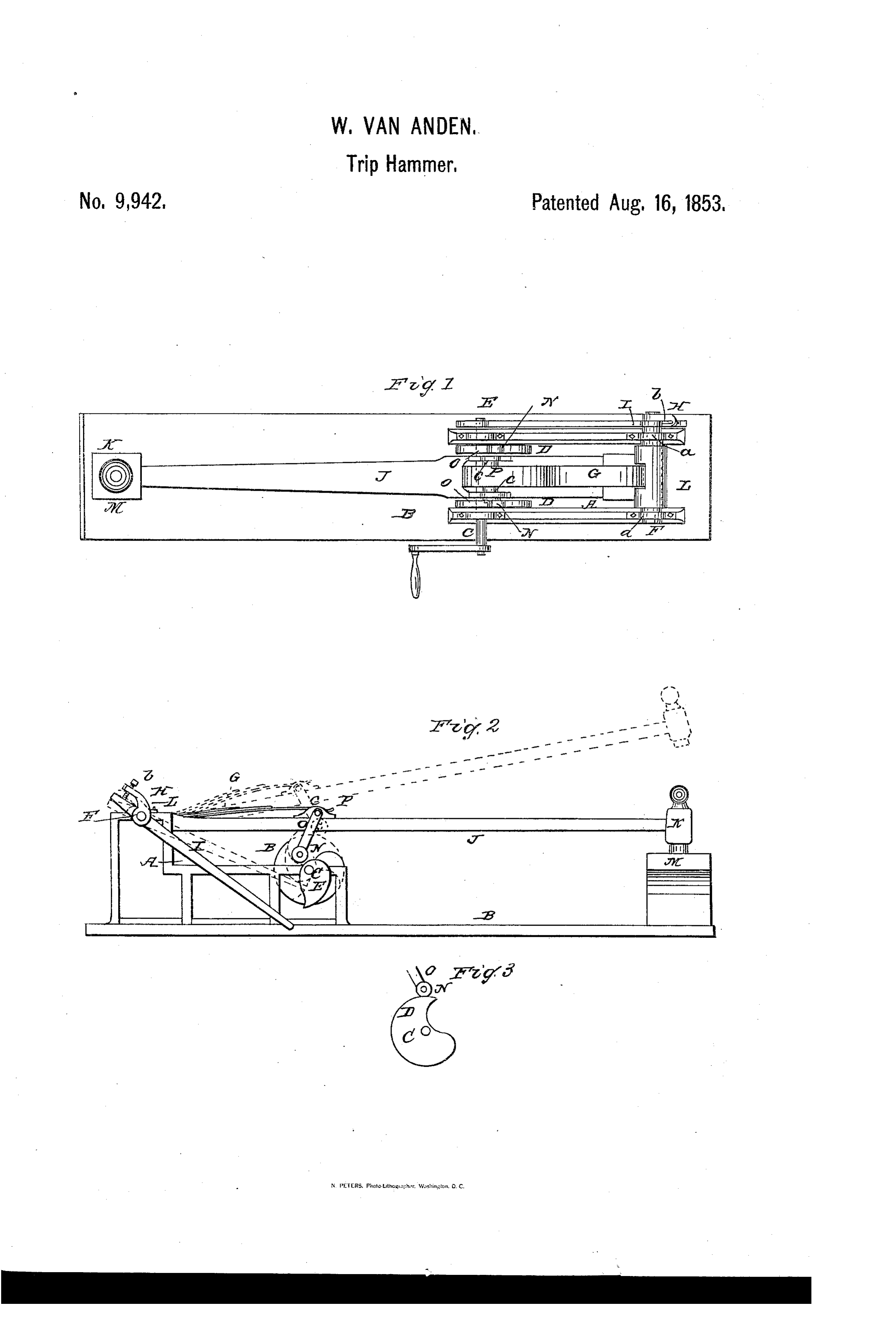
of Poughkeepsie, in the county of Dutchess J, is the hammer-shaft, having the ham and State of New York, have invented a mer, K, on its outer end; the opposite end 80 new and Improved Trip-Hammer; and I do of the hammer-shaft is attached to a collar, hereby declare that the following is a full, L which fits loosely around the shaft, F, to clear, and exact description of the construc which the spring, G, is attached; as seen in tion and operation of the same, reference Fig. 1.
being had to the annexed drawings, making M, is the anvil or block, on which the ham. 65 O a part of this specification, in which - mer strikes.
Figure 1, is a plan or top view of my im N, N, are two friction rollers, attached to proved trip-hammer. Fig. 2, is a side ele a frame, O, the upper part of which is at Vation of the same. Fig. 3 is a section, show tached to a small shaft, P, working in bear ing more particularly one of the eccentrics, ings, (c), (c) on the hammer-shaft, J. The 70 5 and vibrating friction rollers. Son rollers bear or rest upon the cams, Similar letters of reference indicate cor e
responding parts in each of the several Operation: This will readily be seen. The figures. shaft, C, is made to rotate, by hand or other This invention relates to certain improve Wise; and the cams, D, D, which rotate with 75 20 ments in trip-hammers, and consists:-1st, the shaft, C, and bear against the friction in having the hammer shaft attached to a rollers, N, N, elevate the hammer-shaft, J. collar, which works loosely around a shaft The cam, E, as it rotates, bears upon and de to which a spring which forces down the presses the lower end of the lever, I. The hammer shaft, is attached. The spring is upper end of the lever, I, consequently bears 80 25 made to act more or less upon the hammer against the set-screw, (b); and the shaft, shaft, by means of a set Screw and lever, F, to which the spring, G, is attached, is against which a cam operates. By this ar turned; and the spring, G, bears or presses rangement, as will be hereafter shown, the upon the hammer-shaft, J.; and, when the hammer may be made to descend with highest points of the cams, D, D, have 85 30 greater or less force, as desired. passed the lowest centers of the friction 2nd, my invention consists in the employ rollers, N, N, the spring, G, of course forces ment or use of vibrating friction rollers, at the hammer shaft, J, downward, and the tached to the hammer shaft, by which vi hammer, K, strikes the anvil or block, M. brating rollers, the most prominent parts By depressing or elevating the set-screw, 90 35 of the cams which elevate the hammer, are (b), there will be a greater or less pressure relieved, instantaneously, of the pressure of of the Spring, G, upon the hammer-shaft: the hammer shaft, directly said prominences for, by depressing the screw, (b)-(see have passed the centers of the vibrating Fig. 2,)—the lower end of the lever, I, is rollers. elevated, and brought nearer the cam, E; 95 40 To enable others skilled in the art to make consequently, there will be a greater action and use my invention, I will proceed to de of the cam, E, upon the lever, I, and the scribe its construction and operation. shaft, F, will be turned considerably, and A, represents a frame, resting upon a bed the spring, G, be made to bear with in piece, B. The frame may be constructed in creased pressure upon the hammer shaft. 100 45 any suitable manner. On the front part of The reverse takes place, when the set screw the frame, A, there is placed, transversely, is elevated, as will be readily understood. a shaft, C, having two cams, D, D, upon it, The cams, D, D, are relieved, instantane and also a cam, E, on the outer side of the Ously, of the pressure of the friction rollers, frame; see Fig. 1. after the highest points of the cams have 05 50 F, is a shaft, placed transversely on the passed the lowest centers of the rollers; for back part of the frame, and working in Suit the frame, O, vibrates, and throws the roll able bearings, (a), (a). To the center of ers off; consequently, the short angles of the this shaft, a spring, G, is attached; and, at cams will not become Worn and rounded, one end, an arm, H, having a set screw, (b) as would be the case, if the rollers were fixed 1.0 55 through it. permanently to the hammer-shaft. I, is a lever placed loosely on the shaft, F; I do not claim elevating the hammer
Page 3
shaft by means of cams; neither do I claim may be made to descend upon the block or the friction rollers, irrespective of the par anvil, M, with greater or less force, as de 20 ticular manner of arranging or attaching sired.
Em to the hammer-shaft, as herein shown; 2. I claim the employment or use of the ut, friction rollers, N, N, attached to a vibrating Having thus described the nature and frame, O, and arranged substantially in the operation of my invention, what I claim as manner as herein shown; for the purpose of 25 new,
and desire to secure by Letters Patent, relieving, instantaneously, the cams, D, D, from the pressure of the rollers, when the
O 1. Attaching a collar, L, to one end of highest points of the cams have passed the the hammer shaft, J.; Said collar, L., Work lowest centers of the rollers; thus prevent ing over a shaft, F, which has a spring, G, ing the wearing of the cams at their high 30 attached to it, for the purpose of forcing est points, as set forth.
down the hammer-shaft. The shaft, F, WM. WAN ANDEN. 5 being provided with a set-screw, (b), or its equivalent, and lever, I, arranged as de Witnesses:
scribed, by which, upon properly adjusting O. D. MUNN, said set-screw, or its equivalent, the hammer ED. POLHAMUs.
Provenance
- Collection
- Cited prior art
- Original PDF
- patentimages.storage.googleapis.com →
- Pages
- 3
- Method
- pdftotext (the PDF's own text layer) + pdftoppm 300dpi page scans
- Source
- Google Patents bibliographic record
- Granted
- 1853-08-16
- Transcribed from
- patentimages.storage.googleapis.com →